Abstract
The article presents results of the research on identification of structure and directional distribution of vibration transferred to car-body from road roughness. It is the case study of multiple sources of vibration interacting on vehicle and vibration transfer into driver and passengers. During the research the passenger car was driven on special test track. It were recorded the vibration signals in 3 orthogonal axes. The sensors were mounted at the floor panel in locations where the vibration are transferred into the human organism. For the purpose of analysis of vibration transfer in term of human perception it is necessary to correlate the vibration energy, frequency and time of exposition. It allows to evaluate exposure on vibration in frequency bands close to natural frequency of chosen human organs. The analysis of time-frequency distribution of the vibration allow to separate the main components of the signal. The paper presents the results of comparison of RMS value of vibration for different axes in measurement points on floor panel.
1. Introduction
Vibration is the mechanical phenomena caused by machines in operation. Generally the vibration is undesirable, wasting energy and creating unwanted effects. The vehicle vibration are one of the most important unwanted effects. It causes decrease of safety and comfort factors and increase of fuel consumption. The vibration problems are very important for vehicle dynamics. It has to be taken into consideration, starting from modeling, designing through production to service and diagnostics of car vehicles [1-7]. The main areas of the author’s interest under the past studies undertaken include an assessment of vibration damping from the perspective of safety and comfort. Furthermore, the author conducted a series of studies pertaining to identification of other vibration sources occurring in vehicles, such as the engine and the power transmission systems [8, 9]. The range of impacts vibrations exposure on a vehicle driver is very broad, starting from the feeling of discomfort to safety hazards caused by vibrations at resonant frequencies of specific organs, thus affecting the driver’s responses. Therefore, it is important to study the paths of vibration propagation from their sources into the human organism and to assess the vibration exposure for different input function conditions [10-12]. The studies discussed in papers [8, 13] illustrate the outcomes of the influence of input parameters on the distribution of the vibrations being generated as well as their propagation.
The paper presents some results of identification of structure and directional distribution of vibration transferred to car-body from road roughness. It is the case of multiple sources of vibration interacting on vehicle and transfer into driver and passengers. In order to examine vibration related phenomena occurring in a moving vehicle or a stationary one with its engine in operation, one should start with identification of vibration sources. The sources of vibration in a vehicle are dynamic forces but also free vibrations as well as forced, self-induced, parametrical, non-parametrical, random and stationary ones, all generated by the driving unit, the power transmission system and the road. The large scope of the vehicle vibration determinants include materials, services and construction (frame) production and repairs [14-17].
2. Biodynamical effects of drivers modeling – state of the art
The scientific problems of vehicle’s vibration in many aspects, especially in term of biodynamic response of the human body to the whole-body vibration, are main goal of many years investigation of Professor Michael Griffin from Southampton. Number of biodynamical models, vibration transmissibility concepts, and human biodynamic responses are considered in [18]. His research show the goal and way of investigation for many researchers [19-23].
The dynamics model of vehicle should permit for analysis of response function of the vehicle or human (occupant) on chosen excitation. The state of the art shows many publications on different approach to vehicle dynamics modeling. The paper [21] presents the three degrees of freedom (3-DOF) Human–Vehicle–Road (HVR) model, comprising a quarter-car and a biomechanical representation of the driver. The model used the Kelvin element as viscoelastic representation for modeling vehicle suspension systems and human muscular–skeletal structures. Differential equations are provided to describe the motions of various masses under the influence of a harmonic road excitation. The paper [21] formulates the optimization problem in terms of the requirements stipulated by ISO 2631 standards and utilizes a quarter-car model coupled with the biodynamical model of the driver. The model has been depicted in Table 1 in which denotes the driver’s mass, stands for the mass of the vehicle body, and signifies the unsprung masses of the suspension. The model has been excited by a ground vertical motion, , with an amplitude A and a frequency . The represents time-depending deflection. The are the viscous damping coefficients and are spring rates.
Table 13-DOF HVR model and equations of the motion [21]
![3-DOF HVR model and equations of the motion [21]](https://static-01.extrica.com/articles/14764/14764-img1.jpg) |
The differential equations of the motion for the 3-DOF are given by: The equations can be expressed in a matrix form (detailed solution has been presented in [21]) it allows to obtain the expressions for the motions and accelerations of the masses , and as equations as follows: |
A generalized nonlinear two-degrees-of-freedom (2-DOF) model has been formulated in [22] for the dynamic analysis of suspension seats with passive, semi-active and active dampers (Table 2). The model incorporates Coulomb friction due to suspension linkages and bushings, forces arising from interactions with the elastic limit stops, a linear suspension spring and nonlinear damping force for passive, semi-active and active dampers, while the contribution due to biodynamics of the human operator is considered to be negligible. The model masses and represent the masses due to occupant upon neglecting its biodynamic interactions and the seat, respectively. The cushion is characterized by linear stiffness and viscous damping coefficient . The suspension is represented by its linear stiffness , a clearance spring , dry friction force (Columb) and a viscous damping coefficient in the case of a passive suspension seat. The and represent the vertical movement of the occupant mass and the suspension seat mass, respectively. The suspension force may be either for the active. The forces due to the passive components of the suspension are derived from the algorithm where represents the displacement excitation at the base of the seat.
Table 2Analytical 2-DOF model of the seat suspension and equations of the motion [22]
![Analytical 2-DOF model of the seat suspension and equations of the motion [22]](https://static-01.extrica.com/articles/14764/14764-img2.jpg) | The equations of the motion for the 2-DOF suspension seat are given by: |
New approach to system modeling based on possibilities of Finite Element or Neural Network methods allows to develop models dedicated to realize specific functions [24, 25].
3. Research method
The validity of the analytical models have to be examined as comparison to the results obtained on real object. The research studies discussed in the article was conducted on an real object. The passenger car was driven on special test track, without any turns. The profile of the test track, as the road roughness, was set as concrete slab connected every next 5 meters. It was prepared as simulation of driving shock impulse.
Vibration signals were measured on the floor panel at 4 points of location. In order to refer the obtained results to the analysis of the passenger exposure to vibrations, the measuring points were arranged at locations where the vibration are transferred into the human organism, i.e. where feet rested.
Fig. 1Research and testing diagram and location of the vibration sensors
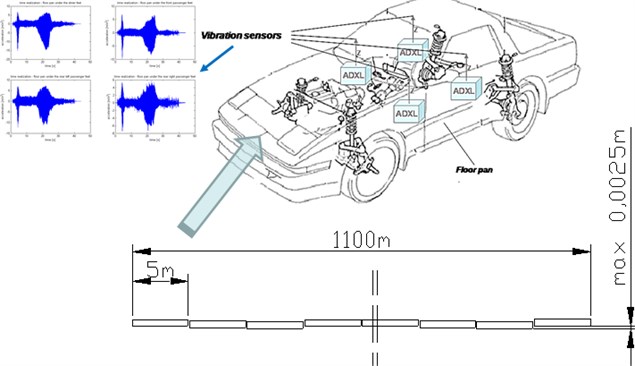
The measurement chain is consisted of the ADXL piezoelectric sensors, a measuring unit, the μDAQ USB-30A16 data acquisition card and a computer featuring the software. The testing diagram has been depicted in Fig. 1.
4. Research results
For the purpose of proper identification of vibration transferred to car-body from road roughness it is necessary to provide measurement in multiple points located on vehicle construction. Human vibration perception depends on area and place of contact of human organism and vibrating machine. It depends also on dynamics of the vibration and exposure time. The identification of vibration transfer from road roughness to car-body in driving car was performed as the analysis of transformation of signals in time and frequency domains. This method of vibration signal processing allows to observe changes of the energy in selected frequency bands and correlate it with time.
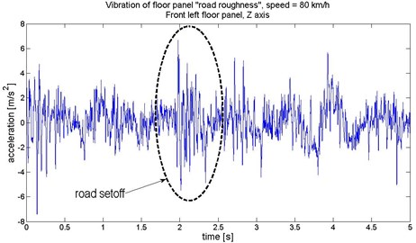
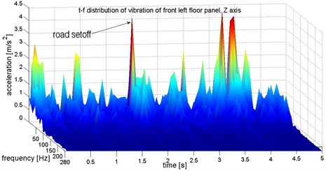
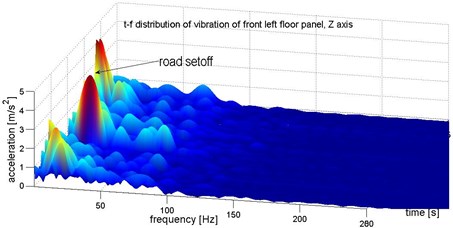
The Figure 2 shows example of identification of vibration increase caused by impulse of road set off. The analysis of time-frequency distribution of the vibration allow to exactly separate the related component of the signal. The speed of the vehicle was set as constant, during the research, so the vibration generated from the engine and powertrain was assumed as constant.
Fig. 2Identification of structure of vibration on front left floor panel (under the driver feet)
a)
b)
c)
Fig. 3Vibration of front left floor panel (under the driver feet) in 3 orthogonal axes
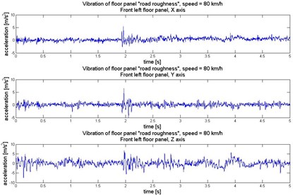
a)
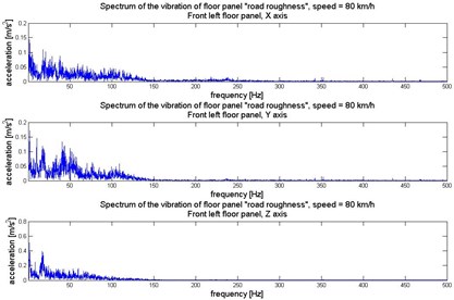
b)
Fig. 4Vibration of front right floor panel (under the front passenger feet) in 3 orthogonal axes
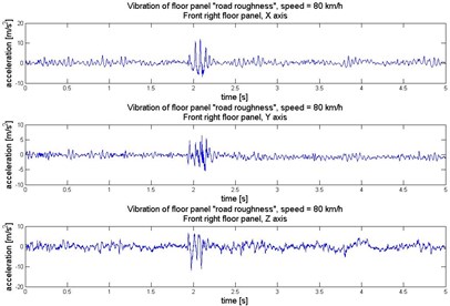
a)
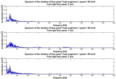
b)
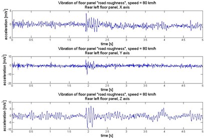
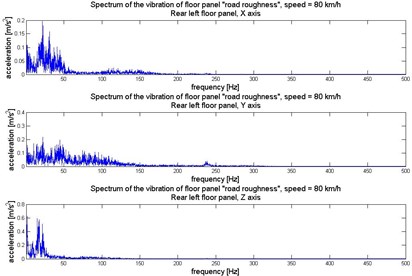
Fig. 5Vibration of rear left floor panel (under the left rear passenger feet) in 3 orthogonal axes
a)
b)
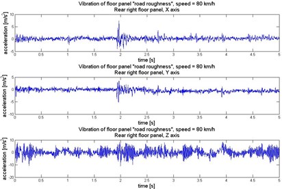
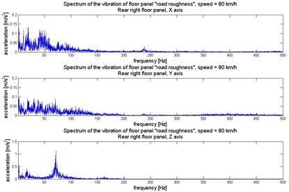
Fig. 6Vibration of rear right floor panel (under the right rear passenger feet) in 3 orthogonal axes
a)
b)
Human perception of vibration also depends on the direction of the exposition. The exposure to vibration has to be consider in 3 orthogonal axes: – horizontally along the vehicle axis, – horizontally crosswise the vehicle axis, and – vertically and perpendicularly towards plane . To analyse the dynamics of the vibration the Fast Fourier Transformation has been proceed on the signals. It allows to evaluate the main frequency components of the vibration. Time and frequency realization of the vibration registered under the passengers feet in 3 axes have been illustrated in Figures 3-6.
During the propagation of vibration waves in solid structure in theory the dispersion of the energy can be observe. For structures with combined shapes and profiles sometimes some increase of vibration can be observe because of multi natural frequencies for different parts of the structure. One of the most popular global estimators of energy of the vibration is RMS (Root Mean Square). The comparison of RMS value of vibration for different axes in measurement points on floor panel have been depicted in Fig. 7.
Fig. 7Comparison of RMS vibration of floor panel under the feet of passengers: 1 – X axis, 2 – Y axis, 3 – Z axis
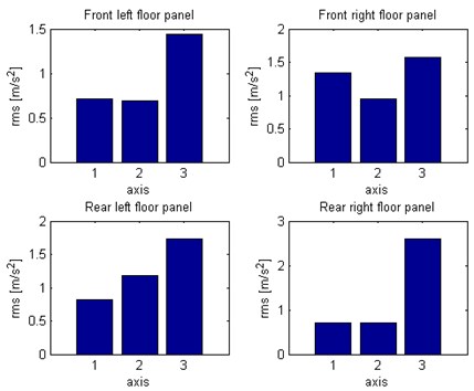
Fig. 8Distribution of acceleration of vibration in X axis direction (horizontally along the vehicle) – floor panel under the feet of passengers
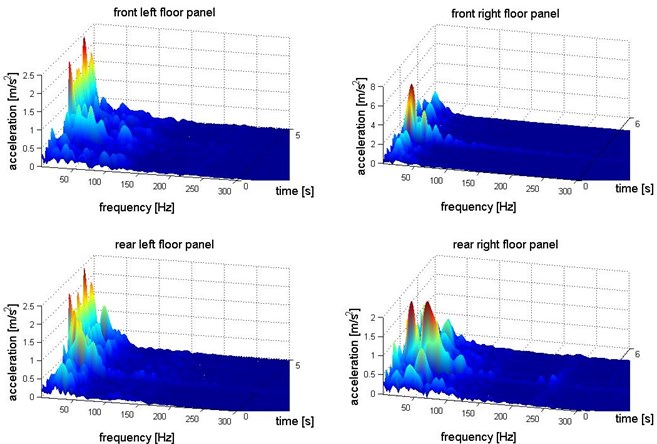
Fig. 9Distribution of acceleration of vibration in Y axis direction (horizontally crosswise the vehicle) – floor panel under the feet of passengers
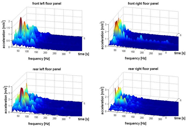
Fig. 10Distribution of acceleration of vibration in vertical direction (Z axis) – floor panel under the feet of passengers
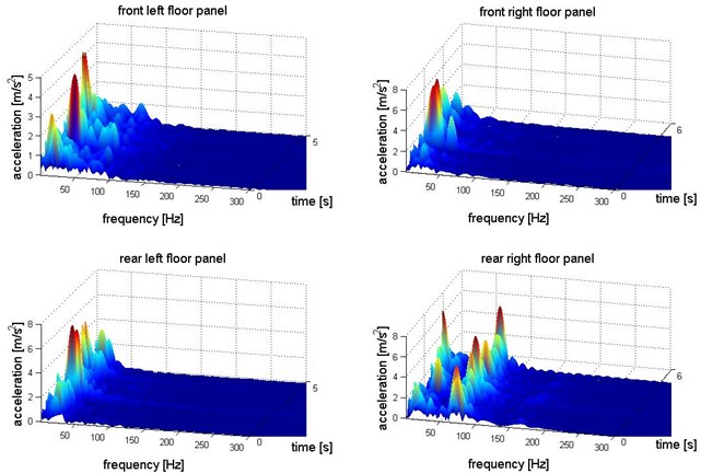
For the purpose of analysis of vibration transfer in term of human perception it is necessary to correlate the vibration energy, frequency and time of exposition. It allows to evaluate exposure on vibration in frequency bands close to natural frequency of chosen human organs. There are many methods for multidimensional transformation of the signal. The paper presents the results of the time-frequency distribution of the acceleration of vibration obtained by the Short Time Fourier Transformation. It shows the main components of the energy of the vibration and frequency bands of exposure [26-28].
The Figures 8-10 show time-frequency structure of the vibration transferred to passengers via the feet in 3 orthogonal axes. This presentation of the vibration enables identification of the propagation of the vibration of driving car and calculation of energy changing for chosen frequency bands.
5. Conclusions
The proper validate analytical model of vehicle dynamics allows simulations many driving conditions and response functions. One of the most popular application of the model is analysis of different control system for isolation from vibration of road roughness by spring and damping system of the suspension. For the comfort of the passangers the perception of vibration is very important. The goal of prevencion from vibration in passanger cabin is very difficult to reach. The isolation of chosen frequency bands of the vibration can be much easier. It is fundamental to properly identyfy the vibration transfer to car-body. All kind of vibration sources have to be consider as generators during car driving. The results of the research show that structures of the vibration are different for the directions and localization in the vehicle structure. It has to be take into consideration the various kinds and production technologies of means of transport [29, 30]. To complete the research on vibration transfer to car-body by driving car there have to be conducted many more research on different vibration generators or driving speed.
The simultaneous analysis of distribution of RMS and time, frequency functions of vibration for different axes in measurement points on floor panel allow to compare propagation of the vibration. It have been observed that most of the energy of the vibration under the passengers feet are transferred in axis direction (vertical). The highest vibration were registered under the feet of rear right passenger.
The time-frequency structure of vibration of the floor panel allow identification of the main components of the vibration in terms of dynamics (frequency) and time of exposition. It can be observed that local maximum values of vibration for some frequencies are excited in limited time periods.
The results show how many conditions have to be taken into consideration for vehicle dynamics model. The diffrences in vibration signals on floor panel in different location and direction (3 orthogonal axes) requires more complicated multibody model.
References
-
Bubulis A., Reizina G., Korobko E., Bilyk V., Efremov V. Controllable vibro-protective system for the driver seat of a multi-axis vehicle. Journal of Vibroengineering, Vol. 13, Issue 3, 2011, p. 552-557.
-
Ragulskis K., Kanapeckas K., Jonušas R., Juzėnas K. Vibrations generator with a motion converter based on permanent magnet interaction. Journal of Vibroengineering, Vol. 12, Issue 1, 2010, p. 124-132.
-
Grządziela A. Modelling of propeller shaft dynamics at pulse loadon structure and directional distribution of vibration generated by engine in the location where vibrations penetrate the human organism. Polish Maritime Research, Vol. 15, Issue 4, 2008, p. 52-58.
-
Tuma J., Šimek J., Škuta J., Los J. Active vibrations control of journal bearings with the use of piezoactuators. Mechanical Systems and Signal Processing, Vol. 36, Issue 2, 2013, p. 618-629.
-
Lozia Z. Truck front wheels and axle beam vibrations. 5th Mini Conference on Vehicle System Dynamics, Identification and Anomalies, Budapest, Hungary, 1996.
-
Lozia Z. A two-dimensional model of the interaction between a pneumatic tire and an even and uneven road surface. Vehicle System Dynamics, Vol. 17, 1988, p. 227-238.
-
Michalski R., Wierzbicki S. An analysis of degradation of vehicles in operation. Maintenance and Reliability, Vol. 1, Issue 3, 2008, p. 30-32.
-
Burdzik R. Material vibration propagation in floor pan. Archives of Materials Science and Engineering, Vol. 59, Issue 1, 2013, p. 22-27.
-
Burdzik R. Monitoring system of vibration propagation in vehicles and method of analysing vibration modes. Springer, Heidelberg, 2012, p. 406-413.
-
Paddan G., Griffin M. Evaluation of whole-body vibration in vehicles. Journal of Sound and Vibration, Vol. 253, Issue 1, 2002, p. 195-213.
-
Korzeb J., Nader M., Rózowicz J. Review and estimation of traffic generated vibration developed in proximity of Warsaw subway line. 12th International Congress on Sound and Vibration, 2005, p. 5048-5055.
-
Rózowicz J., Nader M., Korzeb J. Traffic generated vibration impact on buildings. 12th International Congress on Sound and Vibration, 2005, p. 1594-1600.
-
Burdzik R., Folęga P., Łazarz B., Stanik Z., Warczek J. Analysis of the impact of surface layer parameters on wear intensity of frictional couples. Archives of Materials and Metallurgy, Vol. 57, Issue 4, 2012, p. 987-993.
-
Blacha L., Siwiec G., Oleksiak B. Loss of aluminium during the process of Ti-Al-V alloy smelting in a vacuum induction melting (VIM) furnace. Metalurgija, Vol. 52, Issue 3, 2013, p. 301-304.
-
Węgrzyn T., Piwnik J., Burdzik R., Wojnar G., Hadryś A. New welding technologies for car body frame welding. Archives of Materials Science and Engineering, Vol. 58, Issue 2, 2012, p. 245-249.
-
Węgrzyn T., Piwnik J., Łazarz B., Hadryś D. Main micro-jet cooling gases for steel welding. Archives of Materials and Metallurgy, Vol. 58, Issue 2, 2013, p. 551-553.
-
Lisiecki A. Diode laser welding of high yield steel. Proceedings of SPIE, Vol. 8703, 2012.
-
Griffin M. J. Biodynamic response to whole-body vibration. The Shock and Vibration Digest, Vol. 13, Issue 3, 1981.
-
Thompson A. G., Pearce C. E. M. RMS values for force, stroke and tyre deflection in a quarter-car model active suspension. Vehicle System Dynamics, Vol. 39, 2002, p. 57-75.
-
Kuznetsov A., Mammadov M., Sultan I. A., Hajilarov E. Vibration analysis optimization of parameters of the two mass model based on Kelvin elements. Proceedings of the Eighth IEEE International Conference on Control and Automation, China, Xiamen, 2010, p. 1326-1332.
-
Kuznetsov A., Mammadov M., Sultan I., Hajilarov E. Optimization of a quarter-car suspension model coupled with the driver biomechanical effects. Journal of Sound and Vibration, Vol. 330, 2011, p. 2937-2946.
-
Bouazara M., Richard M. J., Rakheja S. Safety and comfort analysis of a 3-D vehicle model with optimal non-linear active seat suspension. Journal of Terramechanics, Vol. 43, 2006, p. 97-118.
-
Kardas-Cinal E., Droździel J., Sowiński B. Simulation study of a relation between derailment coefficient and track condition. Archives of Transport, Vol. 21, Issue 1-2, 2009, p. 85-98.
-
Papalukopoulos C., Giadopulos D., Natsiavas S. Dynamics of large scale vehicle models coupled with driver biodynamic models. Proceedings of the fifth GRACM International Congresson Computational Mechanics, Limassol, 2005.
-
Zheng J., Suzuki K., Fujita M. Car-following behavior with instantaneous driver–vehicle reaction delay: A neural-network-based methodology. Transportation Research Part C, Vol. 36, 2013, p. 339-351.
-
Figlus T., Wilk A., Madej H., Łazarz B. Investigation of gearbox vibroactivity with the use of vibration and acoustic pressure start-up characteristics. Archive of Mechanical Engineering, Vol. 58, Issue 2, 2011, p. 209-221.
-
Dziurdź J. Transformation of nonstationary signals into pseudostationary signals for the needs of vehicle diagnostics. Acta Physica Polonica A, Vol. 118, Issue 1, 2010, p. 49-53.
-
Da̧browski Z., Deuszkiewicz P. Designing of high-speed machine shafts of carbon composites with highly nonlinear characteristics. Key Engineering Materials, Vol. 490, 2011, p. 76-82.
-
Dolecek R., Novak J., Cerny O. Experimental research of harmonic spectrum of currents at traction drive with PMSM. Radioengineering, Vol. 20, Issue 2, 2011, p. 512-515.
-
Lisiecki A. Welding of titanium alloy by disk laser. Proceedings of SPIE, Laser Technology 2012, Applications of Lasers, Vol. 8703, p. 12.
About this article
