Abstract
The present paper deals with free vibration analysis of single lap encastre clinched joints using three dimensional finite element methods. The focus of the analysis is to reveal the influence on the natural frequencies, natural frequency ratios and mode shapes of these joints caused by variations in the material properties of the sheet materials. Numerical examples show that natural frequencies of single lap encastre clinched joints increase significantly as the Young’s modulus of the sheets increase, but only slight changes are encountered for variations of Poisson’s ratios. The mode shapes show that there are different deformations in the jointed section of clinched joints. These different deformations may cause different natural frequency values and different stress distributions. In both cases of transverse free vibration and torsional free vibration, odd mode shapes were found to be symmetrical about the mid-length position and even mode shaps were anti-symmetrical. The amplitudes of vibration at the mid-length of the joints are different for the odd and even modes. The geometry of the lap section is therefore very important and has a very significant effect on the dynamic response of the single lap encastre clinched joints. The main goal of this paper is to give an outline of free vibration characteristics of encastre clinched joints by finite element methods and to provide a basis for further experimental research.
1. Introduction
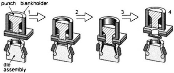
There is an increasing need to design lightweight structures such as vehicle body shells. Advanced joining technology is an integral part of the manufacturing processes of lightweight structures. Many efforts have been spent to develop the suitability of various joining processes for application into lightweight structures [1-5]. Clinching has also been developed rapidly into a new branch of mechanical joining techniques [6]. The clinching process is a method of joining sheet metal or extrusions by localized cold-forming of materials. The result is an interlocking friction joint between two or more layers of material formed by a punch into a special die. Depending on the tooling sets used, clinched joints can be made with or without the need for cutting. The principle of clinching with a round tool is given in Fig. 1. The advantages of the clinching include low energy consumption, a relatively quite process, and the absence of subsidial materials such as rivets or bolts, thus permitting a significant reduction of costs and run time. Clinching is diffusing into a series of different applications such as automotive and aerospace industry.
Fig. 1Principle of clinching with a round tool
The static and fatigue behavior of the clinched joints has been the subject of a considerable amount of experimental and numerical studies. Hamel et al. [7] developed an elastic-plastic incremental finite element (FE) computer code for studying clinch forming with respect to process parameters. The results were compared with experimental data and numerical results calculated with a static implicit method. Varis [8] pointed out several problems encountered in the long-term use of a clinching process and both the lack of systematic maintenance and continuous follow-up were discussed. Carboni et al. [9] investigated the fatigue behaviors of clinched joints and found that the influence of joint configuration is not significant. The stress ratio that in fatigue tests, however, will completely changes the failure mode. De Paula et al. [10] carried out FE simulations of the clinch joining of metallic sheets. The simulations covered the effect of these changes on the joint undercut and neck thickness. The relevant geometrical aspects of the punch/die set were determined and the importance of an adequate undercut on the joint strength was confirmed. A parametrical study based on the Taguchi’s method, has been conducted by Oudjene and Ben-Ayed [11] to properly study the effects of tools geometry on the clinch joint resistance as well as on its shape. In a further study [12], a response surface methodology (RSM), based on Moving Least-Square (MLS) approximation and adaptive moving region of interest, was presented by Oudjene et al. for shape optimization of clinching tools. The geometries of both the punch and the die were optimized to improve the joints resistance to tensile loading. Despite these impressive developments, however, research in the dynamic properties of clinched joints is relatively unexplored. Hence there is a need for a contribution of knowledge to the understanding of the vibration characteristics of the clinched joints.
The present paper deals with free vibration analysis of single lap jointed encastre clinched joints using three dimensional (3D) FE methods. The FE analyses are carried out using the commercially-available ANSYS FEA program. Numerical examples are provided to show the influence on the natural frequencies, natural frequency ratios and mode shapes of the single lap jointed encastre clinched joints of different characteristics of sheets to be jointed. Free vibration analysis data were used in conjunction with mathematical mode to establish the relationship between the natural frequencies and the Young’s modulus. The mode shapes were discussed for investigating the relative amplitudes of free vibration of the single lap-jointed encastre clinched joints. In order to obtain a full picture of the free vibration properties of the single lap jointed encastre clinched joints, the range of Young’s modulus and Poisson’s ratios covers the mechanical properties of various types of lightweight materials. A great number of mode shapes corresponding to different combinations of Young’s modulus and Poisson’s ratios were obtained from the parametric studies. However, only mode shapes of the typical combinations of Young’s modulus and Poisson’s ratios discussed in this work.
Table 1Mechanical properties of sheets to be jointed
Sheets | (GPa) | 0.1, 0.2, 0.5, 1, 2, 5, 10, 20, 50, 100 |
0.3, 0.32, 0.34, 0.36, 0.38, 0.4 |
Fig. 2A single lap encastre clinched joint
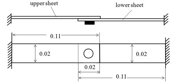
2. Configuration and properties of single lap encastre clinched joints
As shown in Fig. 2, the single lap encastre clinched joint studied in the present work includes the upper sheet and lower sheet. The two sheets were of dimensions 0.11 m long, 0.02 m wide, 0.002 m thickness and were joined together in the central part. Table 1 shows the mechanical properties of the sheets. The range of sheet properties considered covers the mechanical properties of various types of lightweight materials such as lightweight alloy and polymers.
3. Finite element modelling
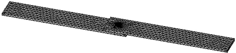
The original element mesh of the single lap encastre clinched joint is shown in Fig. 3. Because of the complex geometry and 3D nature of the free vibration on the single lap encastre clinched joint, solid187 elements were used to model the joint. Solid187 element is a higher order 3D, 10-node element which has a quadratic displacement behavior and is well suited to modeling irregular meshes. In order to save computation time small elements are used within and around the jointed section and larger elements are used in the outer regions. To obtain the sophisticated features such as design optimization and adaptive meshing, ANSYS Parametric Design Language (APDL) was used in FE modeling of the single lap encastre clinched joint. The material parameters of the sheets were input via the APDL input files. The natural frequencies (Eigenvalues) and mode shapes (eigenvectors) of the free vibration of single lap encastre clinched joints were extracted for different combinations of the Young’s modulus and Poisson’s ratio of the sheets to be jointed.
Fig. 3Original element mesh of the single lap encastre clinched joint
4. Free transverse vibration analysis
Each of the values of Young’s modulus (given Table 1, ) was used with each of the values of Poisson’s ratios (given Table 1, ) in an FE analysis. The transverse natural frequencies of the single lap encastre clinched joints were derived from each computation corresponding to a pair of sheet properties. These results are presented in graphical formats and are discussed in the following.
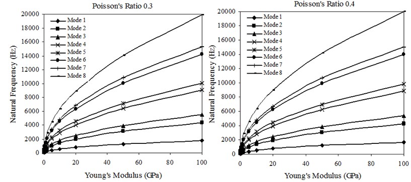
4.1. Effect of Young’s modulus of sheets on transverse vibration behavior of clinched joints
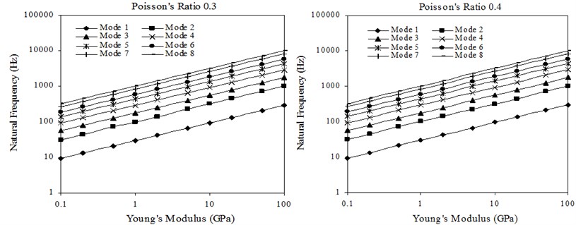
Fig. 4 shows the transverse natural frequencies versus Young’s modulus of sheets with 0.30 and 0.40. The material density is 2500 kg/m3, which is close to the material density of aluminum alloy. In the cases of Poisson’s ratios of 0.32, 0.34, 0.36 and 0.38, similar variations of transverse natural frequency with Young’s modulus of sheet as in the case of Poisson’s ratios of 0.30 and 0.40 are observed. It is clear that the transverse natural frequencies increase greatly as the Young’s modulus of sheets increase.
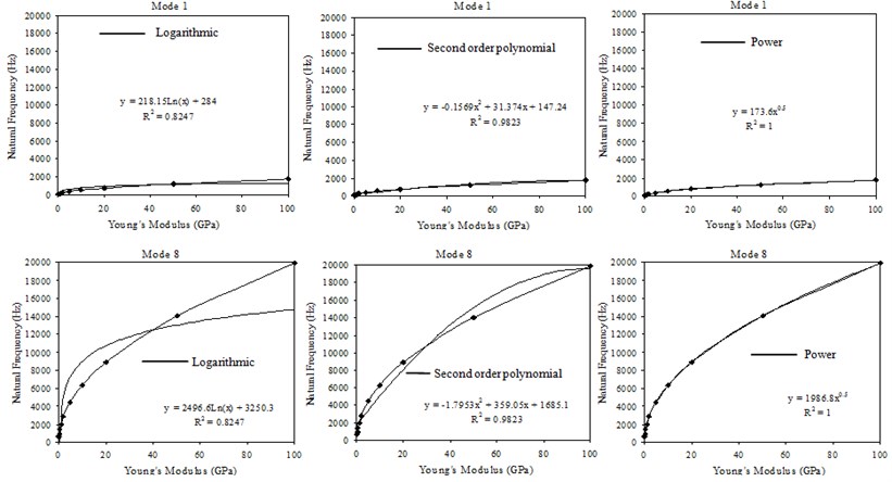
In order to find the relationship between the transverse natural frequencies and the Young’s modulus the natural frequencies were used in conjunction with different type of trendlines for mode 1 and mode 8 as shown in Fig. 5. In the cases of mode 2 to mode 7, similar variations as in the case of mode 1 and mode 8 are observed. It is clear that the power trendline provides the perfect fit ( – squared value ) for the relationship between the transverse natural frequencies and the Young’s modulus and a mathematical model of the following type is expected:
And it can be rewritten as:
Fig. 4Transverse natural frequencies versus Young’s modulus of sheets
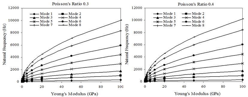
Fig. 5Conjunction of the natural frequencies with different type of trendlines
It is obvious that Eq. (2) is a linear equation in coordinates. In other words the transverse natural frequency curves should became a set of parallel straight lines in the coordinates. These straight lines have the same slope 0.5 but different intersections with the axis. Fig. 6 shows the straight lines for the case of Poisson’s ratios 0.30 and 0.40 in the coordinates. For the cases of Poisson’s ratios 0.32, 0.34, 0.36 and 0.38, there are similar trends in the variations of the transverse natural frequencies with Young’s modulus.
Fig. 6Relationship between F and Es in the ln-ln coordinates
4.2. Effects of Poisson’s ratios of sheets on transverse vibration behavior of clinched joints
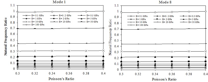
Ranges to the first and eighth natural frequency ratios, caused by varying the Poisson’s ratio of sheet materials are shown in Fig. 7. In the cases of mode 2 to mode 7, similar variations of natural frequency ratios with Poisson’s ratio of sheets as in the case of mode 1 and mode 8 are observed. Here the natural frequency ratio is the ratio of the natural frequency of a mode calculated at a particular Poisson’s ratio to the natural frequency of the same mode calculated for a reference encastre beam of the same geometry and dimensions as the single lap encastre clinched joint but without joint. These values were used in the analysis in order to obtain a reference bound for the transverse natural frequencies of a single lap-jointed lightweight material encastre beam [13]. From Fig. 7 it is seen that the natural frequency ratios of the transverse modes increase slightly as the Poisson’s ratio of sheets increase.
Fig. 7Transverse natural frequency ratios versus Poisson’s ratio of sheets
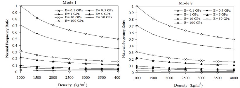
4.3. Effects of density of sheets on transverse vibration behavior of clinched joints
Transverse natural frequencies versus Young’s modulus of sheets with material densities 1000 kg/m3 and 4000 kg/m3 is shown in Fig. 8. The Poisson’s ratio is 0.32, which is close to the Poisson’s ratio of aluminum alloy. In the cases of material densities of 1500, 2000, 2500, 3000 and 3500 kg/m3, similar variations of transverse natural frequency with Young’s modulus of sheets as in the case of material densities 1000 kg/m3 and 4000 kg/m3 are observed. For easy comparison, the transverse natural frequencies versus Young’s modulus of sheets with material densities 1000 kg/m3 and 4000 kg/m3 are drawn using the same co-ordinate scales. It is obvious that, in this case, the transverse natural frequencies decrease as the material densities of the sheet increase. Ranges to the first and eighth natural frequency ratios, caused by varying the material densities of the substrate material are shown in Fig. 9. In the cases of mode 2 to mode 7, similar variations of natural frequency ratios with material densities of sheets as in the case of mode 1 and mode 8 are observed. It can be seen from Fig. 9 that the natural frequency ratios of the transverse modes decrease as material densities of sheets increase.
Fig. 8Transverse natural frequencies versus Young’s modulus of sheets
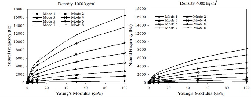
Fig. 9Transverse natural frequency ratios versus densities of sheets
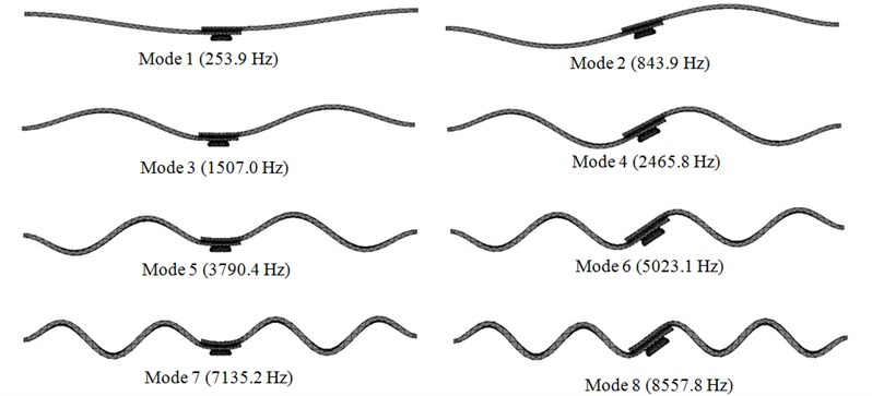
4.4. Discussion of transverse vibration mode shapes
A great number of vibration mode shapes corresponding to different Young’s modulus and Poisson’s ratios of sheets were obtained from the parametric studies. However, the vibration mode shapes were found to be similar throughout the test range and so only a few, typical mode shapes will be discussed in this paper. For ease of comparison, a reference beam was used for ease of comparison of mode shapes. The first eight transverse mode shapes of the single lap encastre clinched joint corresponding to , 70 GPa and 2700 kg/m3 are shown in Fig. 10. It can be seen that the amplitudes of vibration at the mid-length of the joints are different for the odd and even modes. For the odd modes (1, 3, 5 and 7), symmetry is seen about the mid-length position. At these positions, the amplitudes of transverse free vibration are about equal to the peak amplitude. Thus, the geometry of the lap joint is very important and has a very significant effect on the dynamic response of the single lap encastre clinched joints. Conversely, for the even modes 2, 4, 6 and 8, anti-symmetry is seen about the mid-length position and the amplitude of transverse free vibration at this position is approximately zero. Hence, variations in the structure of the lap joint have relatively less effect on the dynamic response of the the single lap encastre clinched joints.
Fig. 10First eight transverse free vibration mode shapes of the single lap encastre clinched joint
5. Free torsional vibration analysis
It can be seen from FE simulation results that the effects of sheet material properties on the torsional vibration behaviour of clinched joints are very similar with the effects on the transverse vibration behaviour of clinched joints. Therefore this section only focus on the effect of Young’s modulus of sheet materials and transverse vibration mode shapes.
5.1. Effect of Young’s modulus of sheets on torsional vibration behavior of clinched joints
Fig. 11 shows the torsional natural frequencies versus Young’s modulus of sheets with and . In the cases of Poisson’s ratios of 0.32, 0.34, 0.36 and 0.38, similar variations of transverse natural frequency with Young’s modulus of sheet as in the case of Poisson’s ratios of 0.30 and 0.40 are observed. It is clear that the torsional natural frequencies increase greatly as the Young’s modulus of sheets increase.
Fig. 11Torsional natural frequencies versus Young’s modulus of sheets
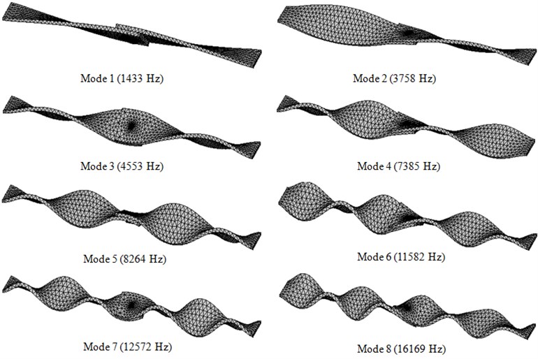
5.2. Discussion of torsional free vibration mode shapes
The first eight torsional free vibration mode shapes of the single lap encastre clinched joint corresponding to , 70 GPa and 2700 kg/m3 are shown in Fig. 12. It can be seen that the amplitudes of vibration at the mid-length of the joints are different for the odd and even torsional modes. For the odd modes, symmetry is seen about the mid-length position. The amplitude of torsional free vibration at this position is approximately zero and the mode shape at the lap joint is smoother. Hence, variations in the structure of the lap joint have relatively less effect on the dynamic response of the the single lap encastre clinched joints. Conversely, for the even modes 2, 4, 6 and 8, anti-symmetry is seen about the mid-length position and the mode shape at the lap joint is somewhat distorted. This difference can be seen especially at higher modes. Thus, the geometry of the lap joint is very important and has a very significant effect on the dynamic response of the single lap encastre clinched joints.
Fig. 12First eight torsional free vibration mode shapes of the single lap encastre clinched joint
6. Conclusions
The free vibration characteristics of single lap encastre clinched joints are investigated numericaly by FE methods. The following conclusions can be drawn based on the results obtained from the present investigation:
- The natural frequencies of single lap encastre clinched joints increase significantly as the Young’s modulus of sheets increase, but only slightly change are encountered when the Poisson’s ratio is varied.
- The relationship between the natural frequencies and the Young’s modulus of sheet is satisfactorily represented by an exponential curve.
- The natural frequencies of single lap encastre clinched joints decrease as the material densities of the sheets increase. The natural frequency ratios of the modes decrease as material densities of sheets increase.
In both cases of transverse free vibration and torsional free vibration, the amplitudes of vibration at the mid-length of the joints are different for the odd and even modes. The geometry of the lap section is very important and has a very significant effect on the dynamic response of the single lap encastre clinched joints.
References
-
He X. Study on forced vibration behavior of adhesively bonded single-lap joint. Journal of Vibroengineering, Vol. 15, Issue 1, 2013, p. 211-218.
-
He X. Finite element analysis of torsional free vibration of adhesively bonded single-lap joints. International Journal of Adhesion and Adhesives, Vol. 48, 2014, p. 59-66.
-
He X. Finite element analysis of laser welding: a state of art review. Materials and Manufacturing Processes, Vol. 27, Issue 12, 2012, p. 1354-1365.
-
He X. A review of finite element analysis of adhesively bonded joints. International Journal of Adhesion and Adhesives, Vol. 31, 2011, p. 248-264.
-
He X., Gu F., Ball A. Recent development in finite element analysis of self-piercing riveted joints. International Journal of Advanced Manufacturing Technology, Vol. 58, 2012, p. 643-649.
-
He X. Recent development in finite element analysis of clinched joints. International Journal of Advanced Manufacturing Technology, Vol. 48, 2010, p. 607-612.
-
Hamel V., Roelandt J. M., Gacel J. N., Schmit F. Finite element modeling of clinch forming with automatic remeshing. Computers & Structures, Vol. 77, Issue 2, 2000, p. 185-200.
-
Varis J. P. Ensuring the integrity in clinching process. Journal of Materials Processing Technology, Vol. 174, Issue 1-3, 2006, p. 277-285.
-
Carboni M., Beretta S., Monno M. Fatigue behaviour of tensile-shear loaded clinched joints. Engineering Fracture Mechanics, Vol. 73, Issue 2, 2006, p. 178-190.
-
de Paula A. A., Aguilar M. T. P., Pertence A. E. M., Cetlin P. R. Finite element simulations of the clinch joining of metallic sheets. Journal of Materials Processing Technology, Vol. 182, Issue 1-3, 2007, p. 352-357.
-
Oudjene M., Ben-Ayed L. On the parametrical study of clinch joining of metallic sheets using the Taguchi method. Engineering Structures, Vol. 30, Issue 6, 2007, p. 1782-1788.
-
Oudjene M., Ben-Ayed L., Delamézière A., Batoz J. L. Shape optimization of clinching tools using the response surface methodology with Moving Least-Square approximation. Journal of Materials Processing Technology, Vol. 209, 2009, p. 289-296.
-
He X., Oyadiji S. O. Influence of adhesive characteristics on the transverse free vibration of single lap jointed cantilevered beams. Journal of Materials Processing Technology, Vol. 119, 2001, p. 366-373.
About this article
This study is partially supported by National Natural Science Foundation of China (Grant No. 50965009) and Special Program of the Ministry of Science and Technology, China (Grant No. 2012ZX04012-031).
