Abstract
The governing vibration differential equation of a plus planetary gear set has derived from the Lagrange method. Its three often neglected components are considered: [1] the meshing damping, [2] the elastic bearing support of the sun wheel, [3] and the angles between the movement direction of the planet carrier and the gear meshing line. A simulation model for a plus planetary gear set is built. The influence that the key components have on vibration characteristics is analyzed. Model validation is performed by comparing the theoretical, simulated and measured natural frequencies. In order to reduce vibration and noise, a comprehensive finite element model of a plus planetary gear set is built. It provides useful information on dynamic transmission errors of the plus planetary gear set. The tooth profile modification is optimized by using the genetic algorithm. The optimal tooth profile modification is validated by the results of the experiment.
1. Introduction
Planetary gear sets are widely used for automotive automatic transmissions because of their advantages, which include [1] a circular and compact construction, [2] very high and low gear ratios with a small number of teeth, [3] high density of torque and power (as a result of power splitting), and [4] low weight (in comparison with an ordinary gear). However, the noise levels of planetary gear systems is their one potential shortcoming. Major gear noise and vibration problems can be eliminated in the later stages of the transmission unit development. The elimination can be achieved if the designer can evaluate free vibration characteristics of a candidate planetary gear set. The evaluation has to be carried out in different power flow conditions in the early stages of its design.
As for the vibration performance analysis, Liu [1] built a coupled dynamic model. The model involved pure-torsion and translation-torsion types. The nonlinear factors (such as gear backlash, time-varying meshing stiffness and meshing errors) were considered. Meshing errors were solved numerically by the harmonic balance method. Guo and Parker [2] built a model for a compound planetary gear set. They pointed out its shortcomings by comparing the calculated results with the measured results. As for the tooth profile modification for reducing vibration and noise, Ohno [3] and Wang [4] proposed a static three-dimension finite element model. The tooth profile modification was evaluated by the calculated contact stresses at gear meshing positions. However, the above research work ignored not only the influence of the meshing damping but also the elastic bearing support of the sun wheel (which leads to the planetary gear set model to be more rigid). Furthermore, the angles between the movements of the planet carrier and gear meshing were also ignored, which led to imprecise results. The proposed tooth profile modification to reduce vibration and noise is only relatively better. It is not the optimal one in the whole feasible region. Thus, it is necessary to build a reliable vibration characteristics model for planetary gear sets and get the optimal tooth profile modification.
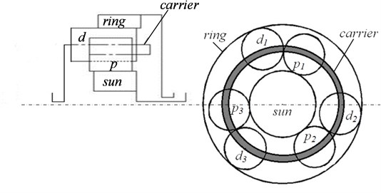
The main objective of this study is [1] to develop a dynamic model, which is capable of predicting the natural modes of a plus planetary gear set with double planet gears (abbreviated for DSNW for convenience and shown in Fig. 1), and [2] to propose an optimization method for tooth profile modification. The effectiveness of the model and the optimal tooth profile modification solution are verified by the results of the experiment.
Fig. 1Schematic diagram of a plus planetary gear set
2. Theoretical analysis
2.1. Vibration differential equations of DSNW
The following simplifications and assumptions are made for the planetary mechanism DSNW [5]:
(1) Each gear is simplified and has an inertial sensor with a lumped mass.
(2) Every gear meshing is simplified and has an elastic spring-damper connection. The meshing only exists on the theoretical meshing line.
(3) The sun gear is allowed to float and is limited to planar movements (no swinging movements).
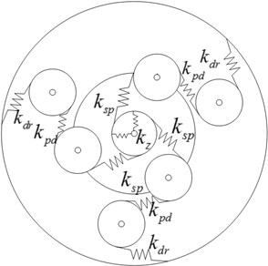
The vibration model of the planetary mechanism DSNW is built (as seen in Fig. 2). Some symbols and subscripts are appointed in advance for convenience. The symbol represents the stiffness. The subscripts , , and represent the sun gear, the ring gear, the planet carrier and bearing, respectively. The subscripts and represent the planet gears. The subscripts and represent the th planet gear and , respectively. The symbol represents the rotational angle, so is the rotational speed and is the angular acceleration. The symbol represents the radius of the gear.
Fig. 2Vibration model of the planetary mechanism DSNW
The parameters of the planetary mechanism DSNW are listed in Table 1.
The planetary mechanism DSNW has six normal working conditions. These conditions (based on the static component) can be uniformed into three different kinds (according to reference [6]). The optional static component can be the planet carrier, the ring gear and the sun gear (respectively), and the other components are randomly used as input and output.
The mathematical vibration model of the planetary mechanism DSNW can be described by the Lagrange equation [7]:
where is the difference between the kinetic energy and the potential energy: , in which is the kinetic energy and is the potential energy; is the th generalized coordinate; is the th generalized force (but not the potential force, such as damping forces).
Table 1The parameters of the planetary mechanism DSNW
Parameters | Elements | ||||
Sun | Planet | Planet | Planet carrier | Ring | |
Module | 4 | 4 | 4 | 4 | |
Tooth width (mm) | 10 | 10 | |||
Addendum coefficient | 1 | 1 | |||
Number of teeth | 32 | 19 | 20 | 77 | |
Base circle (mm) | 58.0 | 34.5 | 36.3 | 139.6 | |
Mass (kg) | 2.0 | 1.8 | 1.8 | ||
Inertia (kg·m2) | 0.00388 | 0.00114 | 0.00132 | 0.104 | 0.724 |
Meshing stiffness (MN/m) | ,, | ||||
Bearing stiffness (MN/m) | |||||
Meshing damping (N·s/m) | ,, | ||||
Bearing damping (N·s/m) | |||||
Angle between the meshing line and the displacement of the planet carrier | |||||
Coefficient of tip clearance | 0.25 | ||||
Elastic modulus (MPa) | 210000 | ||||
Poisson ratio | 0.3 | ||||
Torque (N·mm) | 43000 | ||||
The kinetic energy of the planetary mechanism DSNW yields:
where is the inertia matrix; is the rotational inertia of the component of the transmission; and are the absolute angular velocities of planet gears; is the revolution angular velocity of planet gears (which is also the angular velocity of the planet carrier); and are the relative angular velocities of planet gears to the planet carrier; and are the mass of the th planet gears; is the mass of the sun gear; and are horizontal and vertical displacements of the sun gear (respectively).
The potential energy of the planetary mechanism can be divided into two parts: [1] the potential energy in the meshing point of gear transmission , and [2] the potential energy of the sun wheel elastic bearing support , which is:
where is the meshing stiffness between the sun and the planet gear; is the meshing stiffness between the planet and the ring gear; is the meshing stiffness between planet gears; is the angle between the displacement of the planet carrier and the meshing line between the ring and the planet gear; is the displacement of the planet carrier and the meshing line between the sun and the planet gear. The expression for the damping corresponds with the above stiffness one by one.
The rotational angle and the floating displacement of the sun gear , are treated as generalized coordinates. Eqs. (1)-(7) are combined, and the damped torsional and the translational vibration differential equation of the planetary mechanism DSNW yields:
where , , , are (respectively) generalized coordinates, the inertia matrix, the stiffness matrix and the damping matrix of the planetary system.
Based on the mathematical software MATLAB [8], the natural frequencies for all six working conditions are calculated. The calculation is done by solving the differential equation with the mode superposition method. A part of the calculated results are listed in Table 2. By comparing the theoretical results with the experimental ones [9], the calculation errors are 0.4 %-12.1 %. Therefore it is confirmed that the theoretical modeling method (described above) is an effective way to analyze the free vibration characteristics for plus planetary gear sets.
Table 2Natural frequencies for all working cases
Working type | Order | Theoretical | Simulated | Experimental value | ||
Value | Error (%) | Value | Error (%) | |||
I (the planet carrier is static) | 1 | 1295 | 6.4 % | 1204 | 1.1 % | 1217 |
2 | 4519 | 2.2 % | 4850 | 4.9 % | 4622 | |
3 | 6456 | 2.9 % | 6395 | 1.9 % | 6272 | |
4 | 6559 | 0.8 % | 6637 | 2.0 % | 6510 | |
5 | 8293 | 2.6 % | 8288 | 2.7 % | 8515 | |
6 | 9316 | 0.4 % | 9413 | 1.5 % | 9278 | |
II (the ring gear is static) | 1 | 1295 | 12.1 % | 1204 | 4.2 % | 1155 |
2 | 4211 | 4.3 % | 4187 | 3.7 % | 4039 | |
3 | 6456 | 2.6 % | 6395 | 1.6 % | 6293 | |
4 | 6559 | 1.9 % | 6600 | 1.3 % | 6685 | |
5 | 6718 | 1.1 % | 6637 | 2.3 % | 6790 | |
6 | 8471 | 0.7 % | 8516 | 0.1 % | 8527 | |
III (the sun gear is static) | 1 | 1295 | 9.9 % | 1204 | 2.2 % | 1178 |
2 | 2298 | 9.8 % | 2155 | 3.0 % | 2092 | |
3 | 6456 | 0.5 % | 6395 | 0.4 % | 6421 | |
4 | 6559 | 2.3 % | 6544 | 2.5 % | 6714 | |
5 | 6682 | 1.1 % | 6636 | 1.7 % | 6754 | |
6 | 9123 | 1.0 % | 9280 | 0.7 % | 9216 | |
2.2. Theoretical model of dynamic transmission errors of meshing gears
In order to calculate the transmission error of a pair of meshing planet gears, most research work uses the Ishikawa method [10, 11]. This method treats the gear tooth profile as a combination of a rectangle and a trapezoid (shown in Fig. 3). Bending, shearing and contact deformation are considered.
In the Ishikawa method, the transmission error of a pair of meshing gears is defined as:
where is the tooth composite deviation, which is (where and are the tooth shape deviations (the tip easing quantity included) of the driver and the driven gears at the meshing point; is the integrated tooth pitch deviation between the current meshing tooth pair and the former one); is the tooth composite deformation (its calculation is explained in the Ishikawa method [10, 11] and is not discussed here). According to the data shown in Table 1, the parameters are: , , .
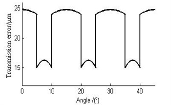
Based on the Ishikawa method, the calculated transmission errors for the planetary mechanism DSNW (Fig. 1) are shown in Fig. 4. However, since the tooth profile is assumed to be a trapezoid in the theoretical model, the stiffness in the middle zone of meshing teeth is smaller than the real one. This could lead to an overestimation of the deformation.
Fig. 3Schematic diagram of the tooth simplification [10]
![Schematic diagram of the tooth simplification [10]](https://static-01.extrica.com/articles/14736/14736-img3.jpg)
Fig. 4The calculated transmission errors
3. Simulation analysis
3.1. Simulation model of vibration characteristics of DSNW
As a complex physical system, the planetary mechanism DSNW can be divided into various minimum basic elements. These elements include the tooth meshing between all gears, the rotational inertia for all independent shafts, bearing, etc. Each minimum basic element is easily modeled according to their own corresponsive theories. The reference [6] proposes a modeling method for any planetary mechanism, which is the simulation software SimulationX. SimulationX is verified to be effective by the data of various experiments. By combining each basic element, a family of simulation models for the planetary mechanism DSNW (for all working cases) can be successfully built. Fig. 5 shows a simulation model for the 1st working case. In this case, the planet carrier is fixed. A part of the simulated natural frequencies for all working cases are listed in Table 2. By comparing the simulated results with the experimental ones, the simulation errors yield and are 0.4 %-4.9 %. It is obvious that the built simulation method is more capable of analyzing the free vibration characteristics for plus planetary gear sets than the theoretical analysis is.
Compared with the theoretical analysis, the simulation tool has special advantages of saving more time and energy. It also allows engineers to pay more attention to the physical system itself and not the miscellaneous mathematical problems. Based on the simulation model, the influence of each component of the planetary mechanism DSNW on the power loss and the vibration amplitude (under each natural frequency) is simulated. Fig. 6 and Fig. 7 (respectively) show the relative power loss and the amplitude of DSNW for the 1st working case. For each natural frequency caused by planet gears, there are two vibration modes with similar amplitudes. Only one mode for these frequencies is listed in Fig. 7 [12]. For convenience, the numbering of the elements and components of the planetary mechanism DSNW is appointed in Table 3 and Table 4, respectively.
Fig. 5Simulation model of DSNW
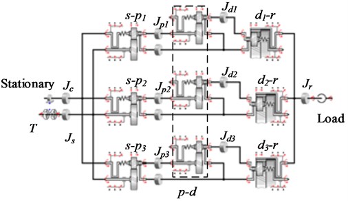
Fig. 6Relative power loss of working case I
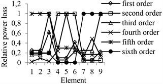
Fig. 7Vibration mode of working case I
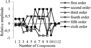
Table 3Elements influencing the free vibration characteristics of DSNW
No. | Elements |
1 | Tooth meshing of gear |
2 | Tooth meshing of gear |
3 | Tooth meshing of gear |
4 | Tooth meshing of gear |
5 | Tooth meshing of gear |
6 | Tooth meshing of gear |
7 | Tooth meshing of gear |
8 | Tooth meshing of gear |
9 | Tooth meshing of gear |
Table 4Components influencing the free vibration characteristics of DSNW
No. | Components |
1 | Revolution of planet gear , |
2 | Revolution of planet gear , |
3 | Revolution of planet gear , |
4 | Rotation of planet gear |
5 | Rotation of planet gear |
6 | Rotation of planet gear |
7 | Rotation of planet gear |
8 | Rotation of planet gear |
9 | Rotation of planet gear |
10 | Sun gear |
11 | Ring gear |
12 | Planet carrier |
Since the power flow routes are different for each working case, there are some differences between the influences of the key elements and the components on the power loss and the amplitude. Based on Fig. 6 and Fig. 7, it is easy to distinguish the elements, which have the strongest influence under all working cases (listed in Table 5). The number of natural frequencies influenced by any key element is the same for all working cases. The key element, which influences the natural frequency of the 1st order, is the tooth meshing of the sun gear with the planet gear . Meanwhile, the key element, which influences the natural frequency of the 3rd order, is the tooth meshing of the planet gear with the ring gear. Based on the simulated results of the planetary mechanism DSNW (for all working cases), all vibration modes can be divided into two types. In one type, the vibration modes are asymmetric and characterized by motions of planets. Meanwhile, all loaded central components are static. In another type, the vibration modes are axi-symmetric, where all double-planet sets move exactly the same way. Meanwhile, the input and output components have their own motions. The vibration mode characteristics are the same as the conclusion from the reference [12]. There, these two types are (respectively) named as the planet mode and the overall mode.
Table 5Key elements and components for all working cases
Working type | Order | No. of key elements | Key elements | Key components |
I | 1 | 1, 2, 3 | sun gear-planet gear | planet gear |
2 | 4, 5, 6 | planet gear -planet gear | planet gear , sun gear | |
3 | 7, 8, 9 | planet gear -gear ring | planet gear | |
4 | 4, 5, 6 | planet gear -planet gear | planet gear | |
5 | 1, 2, 3 | sun gear-planet gear | sun gear, gear ring | |
6 | 7, 8, 9 | planet gear-gear ring | planet gear , sun gear | |
II | 1 | 1, 2, 3 | sun gear-planet gear | planet gear , planet gear |
2 | 4, 5, 6 | planet gear -planet gear | sun gear, planet gear , planet carrier | |
3 | 7, 8, 9 | planet gear -gear ring | planet gear , planet carrier | |
4 | 7, 8, 9 | planet gear -gear ring | planet gear , sun gear | |
5 | 4, 5, 6 | planet gear -planet gear | planet gear | |
6 | 1, 2, 3 | sun gear-planet gear | planet gear , sun gear | |
III | 1 | 1, 2, 3 | sun gear-planet gear | planet gear , planet gear , planet carrier |
2 | 1, 2, 3 | sun gear-planet gear | planet gear ,planet gear , gear ring | |
3 | 7, 8, 9 | planet gear -gear ring | planet gear , planet gear , planet carrier | |
4 | 4, 5, 6 | planet gear -planet gear | planet gear , planet gear , planet carrier | |
5 | 4, 5, 6 | planet gear -planet gear | planet gear , planet gear | |
6 | 7, 8, 9 | planet gear -gear ring | planet gear , planet carrier, gear ring |
3.2. Finite element model of dynamic transmission error of meshing gears
A parametric physical model of the meshing planet gears is developed in order to calculate the dynamic transmission error of meshing gears more accurately. The development happens in the finite element package Ansys-APDL. In order to save computational time, only a part of teeth for the symmetric gears is modeled. The meshing model is shown in Fig. 8. The solid element SOLID164 is selected. Its elastic modulus, the passion ratio and the dynamic friction coefficient are (respectively) set to be 2.1×10⁵ MPa, 0.3 and 0.05.
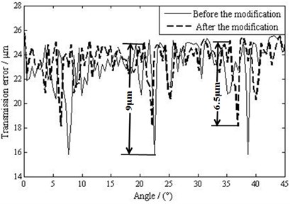
Fig. 9 shows simulated transmission errors of one pair of the meshing planet gears and of the planetary mechanism DSNW. The comparison of the simulated result (in Fig. 9) with the theoretical result (in Fig. 4) demonstrates that the simulated result is more accurate. On the other hand, it is smaller than the theoretical result (since the simulation model considers the real geometrical profile of meshing teeth). The difference is about 7.8 %. Therefore the simulation model successfully predicts the dynamic transmission errors and can be a powerful simulation tool. In addition to this, it is evident that transmission errors are relatively small in the double-teeth meshing zone. Meanwhile, they are big in the single-tooth meshing zone. Therefore large fluctuation exists in their alternating zone. This means that an impact is possible when gears are meshing in or out (due to geometrical interferences). This leads to vibration and noise while meshing. Here, the maximum fluctuation of the transmission error is about 9 μm. Based on the finite element model, the interference value while meshing in is calculated to be 0.01 mm, which should be eliminated in order to avoid the impact while meshing in.
Fig. 8Finite element meshing model of one pair of the meshing planet gears p and d
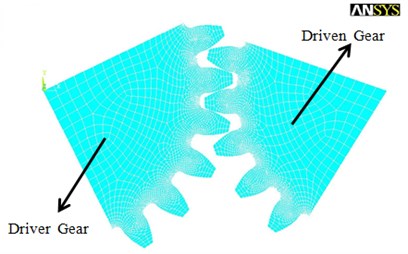
Fig. 9The simulated transmission errors
4. Tooth profile modification method
The modification of the tooth profile of meshing gears is a common method used to reduce vibration and noise. The parameters of this method are the modification width and the depth of the tooth profile. According to the finite element analysis, the interference during meshing is 0.01 mm. Therefore the modification width should not be less than the interference. Additionally, the modification depth should not be less than 0.0001 mm in order get enough high precision. According to the recommended formulae in the reference [13, 14], the maximum modification depth and the maximum modification width are calculated:
where is the normal modulus of the gear. Therefore the optional modification parameters are limited to be ,
Fig. 10Stress distribution on meshing teeth
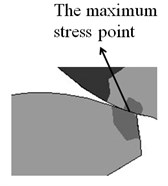
a) Before the modification
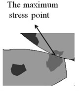
b) After the modification
With the genetic algorithm, the optimal modification parameters of the tooth profile are found in the modification curves. The line-modification method and the parabolic-modification method are used respectively. Since there is no vibration when the transmission error is a constant value, the reciprocal of the fluctuation of the transmission error is selected as an adaptive variable. This is done in order to evaluate the population in the genetic algorithm [13-15]. The optimal tooth profile modification yields from the line-modification method. Here, the optimal modification width is 0.032534 mm and the optimal modification depth is 2.4983 mm. The stress of gears when meshing in (meshing out works similarly) before and after the tooth profile modification is compared in Fig. 10(a) and (b). It is obvious that the maximum stress position exists at the tooth tip before modification. This would cause plastic deformation or the fracture of oil films at the meshing position, i.e. a scuffing failure. However, after the modification, the maximum stress moves close to the middle of the meshing tooth. Meanwhile, there is no interference when meshing in and out, which weakens the impact and therefore achieves a steady transmission [16].
Fig. 9 shows the simulated transmission errors of the meshing planet gears before and after tooth profile modification. It is obvious that the maximum fluctuation amplitude of the transmission error is reduced from 9 μm to 6.5 μm with the optimal tooth profile modification, which is nearly 27.78 %.
5. Experiment study
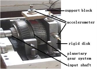
Fig. 11 shows the analysis of the principle for testing the above vibration characteristics. Fig. 12 illustrates the real test-bed and its monitoring devices for gathering and processing vibration and noise signals of the planetary mechanism DSNW. This test-bed consists of a vibration test subsystem, a noise test subsystem and a signal processing subsystem. This test-bed measures the natural frequencies of the planetary mechanism DSNW by using the hammer impacting method. Moreover, it is stated in the references [17-19] that the noise experiment is an effective tool to examine the improvement of the tooth profile modification when reducing vibration and noise.
Fig. 11Schematic diagram of the test rig
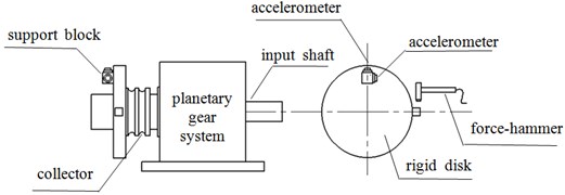
Fig. 12Main testing apparatuses of the test rig
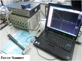
a)
b)
The measured natural frequencies are listed in Table 2. The theoretical model and the simulation model are verified to be capable of predicting free vibration characteristics. The simulation model has higher precision because more real factors are considered.
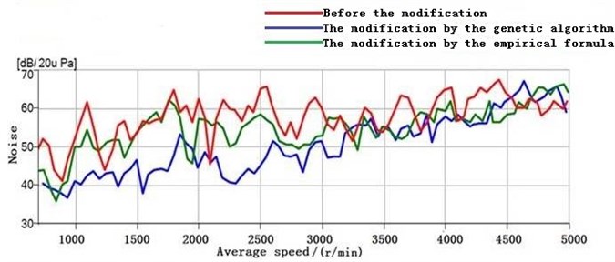
Noise experiments under various speeds for the planetary mechanism with (and without) tooth profile modifications are completed. In order to verify the proposed optimal modification by the genetic algorithm, the modification is also tested according to the traditional Ishikawa formulae. Fig. 13 shows the experimental noise results. They demonstrate that the gear vibration noise is reduced significantly with the proposed tooth profile modification (especially when the speed is from 1000 r/min to 3000 r/min).
Fig. 13Measured noise results
6. Conclusions
(1) The governing vibration differential equation of a plus planetary gear set derives from the Lagrange method. In order to improve calculation precision, three often neglected components are considered: the meshing damping, the elastic bearing support of the sun wheel, and the angles between the movement direction of the planet carrier and tooth meshing. The comparison of the theoretical results and the data of the experiment demonstrates that the calculation errors are about 0.4 %-12.1 %.
(2) The vibration characteristics of a plus planetary gear set for various working cases are simulated. The theoretical and the simulated results are verified by the data of the experiment. The comparison of the simulated results and the data of the experiment demonstrates that the simulation errors are about 0.4 %-4.9 %. This validates that the built simulation method is more capable of analyzing the free vibration characteristics for plus planetary gear sets than the theoretical analysis is. The most important elements and components, which influence the vibration characteristics, are analyzed by using the simulation model.
(3) Combining the finite element method and the genetic algorithm, the optimal tooth profile modification is obtained. Noise experiment results verify that the effectiveness of the proposed tooth profile modification (in order to reduce vibration and noise) is much stronger than the traditional Ishikawa formulae.
References
-
Liu Z., Wu S., Wang X., Qian B. Nonlinear dynamics of compound planetary gear sets based on incremental harmonic balance method. Journal of Vibration and Shock, Vol. 31, Issue 3, 2012, p. 117-122.
-
Guo Y., Parker R. G. Purely rotational model and vibration modes of compound planetary gears. Mechanism and Machine Theory, Vol. 45, 2010, p. 365-377.
-
Ohno K., Tanaka N. Contact stress analysis for helical gear with 3-Dimensional finite element method. Transactions of the Japan Society of Mechanical Engineers, Vol. 64, Issue 628, 1998, p. 4821-4826.
-
Wang J., Howard I. The torsional stiffness of involute spur gears. Mechanical Engineering Science, Vol. 218, 2004, p. 1-12.
-
Wei D., Wang Y. The dynamic characteristics analysis of planet gear train. Journal of Aerospace Power, Vol. 18, 2003, p. 450-453.
-
Yue H., Liu Y., Shi G., Xu X. Free vibration model and characteristics of planetary gear sets. Advanced Materials Research, Vol. 694-697, 2013, p. 383-388.
-
Cai Z., Liu H., Xiang C., Cao H. Research on natural charateristics and sensitivity for torsional vibration of a vehicle multistage planetary gears. China Mechanical Engineering, Vol. 22, 2011, p. 96-101.
-
Khazaee M., Ahmadi H., Omid M. Vibration condition monitoring of planetary gears based on decision level data fusion using Dempster-Shafer theory of evidence. Journal of Vibroengineering, Vol. 14, 2012, p. 838-851.
-
Tordion G. V., Gauvin R. Dynamic stability of a two stage gear train under the influence of variable meshing stiffness. ASME Journal of Engineering for Industry, Vol. 99, 1997, p. 785-791.
-
Li R. Gear strength design information. China Machine Press, Beijing, 1984, p. 77-86, (in Chinese).
-
Blunt D. M., Keller J. A. Detection of a fatigue crack in a UH-60A planet gear carrier using vibration analysis. Mechanical Systems and Signal Processing, Vol. 20, 2006, p. 2095-2111.
-
Kahraman A. Free torsional vibration characteristics of compound planetary gear sets. Mechanism and Machine Theory, Vol. 36, 2001, p. 953-971.
-
Yuan Z. Research on vibration reliability and vibration damping strategy with modification of gears. Northeastern University, Shenyang, 2010, (in Chinese).
-
Bozca M. Torsional vibration model based optimization of gearbox geometric design parameters to reduce rattle noise in an automotive transmission. Mechanism and Machine Theory, Vol. 45, 2010, p. 1583-1598.
-
Lu X. Optimization method to design basis. Tongji University Press, Shanghai, 2003, p. 65-89, (in Chinese).
-
Li X., Jiang S. Nonlinear transient engagement characteristics of planetary gear train. Journal of Vibroengineering, Vol. 15, 2013, p. 933-841.
-
Liu Z. Research on dynamic characteristics of vehicle compound planetary gear train sets. Wuhan University, Wuhan, 2012, (in Chinese).
-
Shan L. Theoretical and experimental study on dynamic characteristics of ring-plate-typed pin-cycloid planetary drive. Dalian Jiaotong University, Dalian, 2010, (in Chinese).
-
Wang S. Theoretical and experimental investigations on dynamics of spur planetary gear transmissions based on planet phasing theory. Tianjin University, Tianjin, 2005, (in Chinese).
About this article
