Abstract
In this paper, a finite element model of a nonlinear rotor-bearing system with two rub-impact faults is established, and the bifurcation and instability characteristics are analyzed along with the changing of rubbing clearance. To verify the results of the theoretical analysis, a rotor-stator rubbing experimental system is established, which contains a pair of oil lubrication cylinder bearing and two disks. With monitoring the rubbing state by a designed electronic device, some qualitative analysis have been done on the rubbing response with different rotor-stator clearance. With investigation of the experimental response in time and frequency domain, some conclusions have be found: for the low eccentricity, when the rubbing clearance decreases, the rubbing fault makes the oil whirl take place earlier, the system of instability speed will decrease slightly, and lost instability through a period-doubling bifurcation. When the rubbing clearance increases, the instability speed will increase slightly, and the rotor system shows a quasi-periodic bifurcation. when the system is in a low speed state, due to the existence of the rubbing fault, the frequency domain appeared multiple frequency components, when the rotating speed is higher, because of the strong “oil whip”, multiple frequency components are not obvious. In addtion, due to the existence of the rubbing fault, the “oil whirl” and “oil whip” of the system become more obvious. The results of the study in this paper will provide some theoretical reference for the characteristic analysis and vibration control of similar rotor-bearing system.
1. Introduction
In the manufacturing and installation process of rotating machinery parts, since some random factors make some problems such as the unbalance of mass, misalignment of rotor and stator and insufficient clearance caused by thermal expansion, which induces the occurrence of rubbing phenomenon between rotor and stator. So the rub-impact fault is a very common and important problem. In recent years, many scholars have made a lot of researches on the nonlinear dynamic problems of the rotor-bearing system with rub-impact fault. Muszynska [1] summarized the friction phenomenon between rotor and stator in rotating machinery, discussed the vibration phenomenon of frictional rotor system. Ehrich [2, 3] analyzed the harmonic, super harmonic and chaos behavior of a rotor which has clearance characteristics and contact nonlinear under the unbalanced incentives. Chu Fulei [4, 5] studied the vibration characteristics of a rotor system with film bearings by numerical integration method, obtained the periodic solution of the system with shooting method and analyzed the stability of the solution combined with Floquet theory. He has found the periodic doubling bifurcation and Hopf bifurcation phenomenon. Lu Wenxiu [6] established a multi-disks rotor system and designed a device to simulate the full rubbing. Different methods are used to analyze the nonlinear response and bifurcation characteristics of the system during rubbing. Results show that higher harmonic components and fractional harmonic components are excited when rubbing occurs with chaotic motion observed with severe rubbing. Jun Jiang et al. [7] have discussed the full annular rub’s stability of the rotor system with cross stiffness coefficients, the research results can explain jumps and bifurcation phenomenon of the rubbing rotor system and the transformation between full annular rub and local rub-impact, finding proper friction coefficient and cross-coupled stiffness coefficient can improve the running stability of the system. In Cong’s [8] paper, he established practice an experimental setup dissimulate the rotor-to-stator rub, and a rub screw is used to simulate the condition of local rub-impact fault. He proposed an Impact Energy Model (IEM) to evaluate the probability or severity of rub-impact fault. Based on the rub-impact dynamic equations of Jeffcott rotor, Zhang Yimin [9, 10] has proposed the analytical method of sensitivity and reliability for the rub-impact rotor system. Wan C. [11] analyzed the chaos and bifurcation response characteristics of local rub-impact fault, for the Jeffcott rotor system with simple supporting and nonlinear supporting. Wang et al. [12] analyzed the nonlinear dynamics of a flexible rotor supported by externally pressurized porous gas journal bearings, and demonstrated the periodic and quasi-periodic response of journal and rotor centre. Chen [13] proposed a nonlinear model in his paper, and used Poincaré maps, bifurcation diagrams, and power spectra to analyze the chaotic behavior and other nonlinear phenomena. Recently, Gjika [14] studied nonlinear dynamic behaviors of turbocharger rotor-bearing system with hydrodynamic oil-film and squeeze film damper in series. He developed a model predicting the nonlinear lateral dynamic response of the rotor-bearing system and validated it with field tests. Using Floquet theory, Chen et al. [15, 16] obtained the stability boundaries of periodic motion in parameter plane of mass eccentricity-rotating speed with numerical integral method. Ji et al. [17] established a single disc flexible rotor-bearing system with a long sliding bearing, and the Hopf bifurcation and stability characteristics were analyzed with a shooting method, and a distinguishing criterion named “practical stability” was provided in his paper. Khanlo et al. [18] investigated the influence of end-support conditions on the chaotic and bifurcation behavior of a rotating flexible shaft-disk system, he found that inclusion of the bearing effects can primarily change the speed ratios at which rub-impact occurs, and the principal and cross-coupling stiffness and damping coefficients have quite different effects in the chaotic behavior of the system. Xie [19] has studied complicated dynamic behaviors of a flexible rotor-bearing system with two unbalanced disks, and pointed out that the response varies in a large extent when the phase angle between the eccentricities of the disks is varying. Over the past few decades, some researchers have studied nonlinear issues and bifurcation phenomena of the rotor-bearing system with M-DOF finite element method. As is well known, rotor system itself is a complicated system; an accurate model has to take into account many factors, such as distribution effect of mass and moment inertia, inner damping, bending and torsion vibration coupling effect, shear effect, and so on. So, it is necessary to set up a more realistic FE model to study the dynamics of nonlinear rotor-bearing system, which is the motivation of this research.
Based on these previous studies, this paper established a rotor-stator rubbing experimental system with two disks which contains a pair of oil lubrication cylinder bearing, and has done some researches on nonlinear response by the sensitive paprameter “rubbing clearance”. The study results will provide theory reference for the fault diagnosis, vibration control and stable operation of the rotor-bearing system.
2. Modeling of the rotor-bearing system
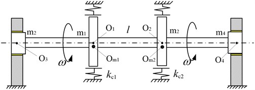
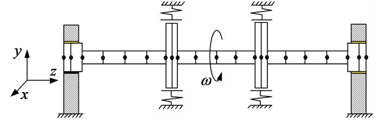
A dynamic model of the rotor-bearing model with double rub-impact faults is shown in Fig. 1, which contains two disks and two same oil lubrication cylinder bearings, the two disks respectively locate at the two trisection points of the shaft. In this paper. As shown in Fig. 1, are the geometric centers of disk1 and disk2 and journal of two bearings respectively; and represent the centroids of the two disks; indicate the concentrated mass of the two disks and journal bearings, respectively; and are the rubbing stiffness; is the length of the rotor, and is the rotating speed of the shaft.
2.1. The establishment of mathematical models
The correlative parameters of the rotor-bearing system are as follows: diameter of the two same disks, 44 mm; and the effective length, 20 mm; rotor shaft radius, 18 mm; the length 720 mm; outer radius of the disks, 160 mm; the thickness of disks, 20 mm; the average oil film thickness 0.18 mm; the eccentricity of the disks is 0.10 mm; rub-impact stiffness, 5×10⁶ N/m; the initial eccentric angles, 0, and the difference of the two angles, 0; the dynamic viscosity of the lubricating oil, 0.018 Pa•s.
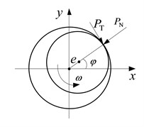
This system is modeled as a M-DOF system by the finite element method (FEM). The finite element model is shown in Fig. 2, each dot in the figure means one node, and each segment represents one element. The rotor shaft is divided into 20 beam elements with 21 nodes, The nonlinear oil-film force at both ends is applied to the right side of the equation with the force vector. The vibration differential equation of the whole system can be written as:
where is the supporting nonlinear force vector of bearings; is the rub-impact force vector; is the unbalance force vector of the disks; is the gravity vector of the whole system.
Fig. 1The dynamic model of the rotor-bearing model with double rub-impact faults
a) A flexible rotor system with rub-impact faults
b) The partial rub-impact model
Fig. 2The finite element model of the rotor-bearing with double rub-impact faults
2.2. Oil-film force model
In this research, it is assumed that laminar and isothermal lubrication occur in short journal bearings [20]. According to the bearing theory, the dimensionless nonlinear oil-film force can be expressed as:
where and are dimensionless displacement in respective direction:
The dimensional oil-film force can be obtained by:
where is the modified sommerfeld number, , is half weight of the rotor, μ is the absolute viscosity of lubricant, is the dimensional thickness of the lubrication film.
2.3. Rub-impact force model
Without taking into account the thermal effects of friction, and assumed that it is an elastic collision processing between stator and rotor, and the rub-impact is local rub-impact. The nonlinear local rub-impact force model of rotor is shown in Fig. 1(b). is the radial collision force; represents tangential friction force; indicates the angle between rub-impact point of normals and axis; is the rotating speed of the shaft; represents the displacement of shaft center. The friction coefficient between rotor and stator is ; represents the clearance between the disk and stator. So the rub-impact force and frictional force can be expressed as below:
where indicates the axis center displacement, ; and represent rub-impact node of displacement in -direction and -direction.
According to the coulomb law, by a series of decomposition transform, the rub-impact force can be expressed as below:
It uses the nonlinear oil-film force of modified Capone model, which has high-accuracy and nice convergent performance.
3. Effect of rub-impact clearance on stability
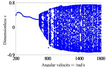
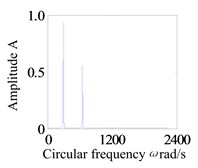
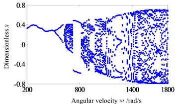
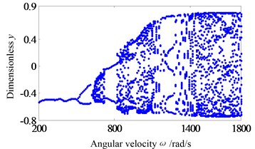
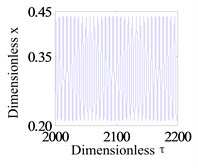
Assumption, the eccentricity of the two disks are 0.04 mm. Firstly, the system operation with a larger rub-impact clearance is studied. Fig. 3 shows the system response of global bifurcation diagram, when the dimensionless rub-impact clearance 0.8. From Fig. 3, It is found that the system suddenly appears quasi-periodic bifurcation (or chaos motion), which can be verified from Fig. 4. Fig. 4(a)-(d) and (e)-(h) are the time-domain waveform, orbit of rotor shaft, Poincaré map and the response spectrum respectively at rotating speed 620 rad/s and 670 rad/s. For the Fig. 4(a)-(d), it can be seen that the axis orbit is a closed loop, the Poincaré sectional view shows one concentration point, the amplitude spectrogram appears not only the rotational frequency component, but also the 2X and 3X frequency components, which are mainly caused by the rub fault. When the rotating speed is 670 rad/s, the axis orbit appears as never repeat curve. And a closed circle appears in the Poincaré map. According to the response spectrum, in addition to the rotational frequency component, it also appears half-frequency component, which indicates that the system shows a half-frequency whirl at this time. It can be seen from Fig. 4(f) that the system occurs quasi-periodic bifurcation at 658 rad/s.
Fig. 3The bifurcation diagrams at the right bearing when δc= 0.8
a)-bifurcation
b)-bifurcation
Fig. 4Curve of the Floquet multipliers for synchronous periodic motion when δc= 0.8
a) Time-domain waveform
b) Journal trajectory
c) Poincaré map
d) Frequency spectra
e) Time-domain waveform
f) Journal trajectory
g) Poincaré map
h) Frequency spectra
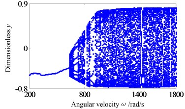
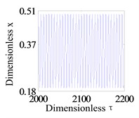
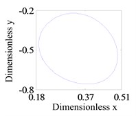
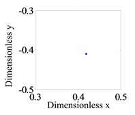
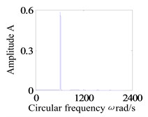
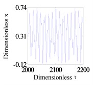
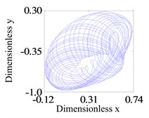
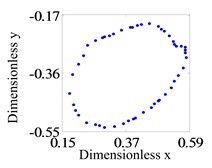
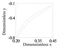
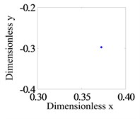
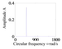
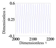
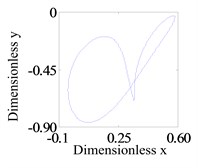
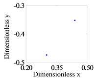
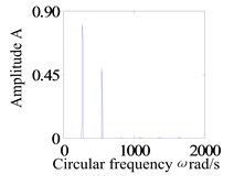
In this section, to research the system operation with a small rub-impact clearance, Fig. 5 shows the system response of global bifurcation diagram, when the dimensionless rub-impact clearance 0.6. It is found from Fig. 5 that the system appears period-doubling bifurcation at 505 rad/s, and then shows a quasi-periodic bifurcation (or chaos motion), which can be verified from Fig. 6. Fig. 6a-d and e-h are the time-domain waveform, orbit of rotor shaft, Poincaré map and the response spectrum respectively at rotating speed 505 rad/s and 550 rad/s. When the rotating speed 505 rad/s, the axis orbit is a closed loop. The Poincaré sectional view shows one concentration point. The amplitude spectrogram appears not only the rotational frequency component, but also the 2X and 3X frequency components, which are mainly caused by the rub-impact phenomenon. When the rotating speed 550 rad/s, the axis orbit appears as two interconnected closed circles. Two concentration points appear in the Poincaré map. According to the response spectrum, in addition to the rotational frequency component and half-frequency component, it also appears 3/2X, 2X, 5/2X and 3X frequency components caused by the rub fault, but these components are not obvious. This indicates that the system motion is period-doubling bifurcation at this time.
Fig. 5The bifurcation diagrams at the right bearing when δc= 0.6
a)-bifurcation
b)-bifurcation
Fig. 6Curve of the Floquet multipliers for synchronous periodic motion when δc= 0.6
a) Time-domain waveform
b) Journal trajectory
c) Poincaré map
d) Frequency spectra
e) Time-domain waveform
f) Journal trajectory
g) Poincaré map
h) Frequency spectra
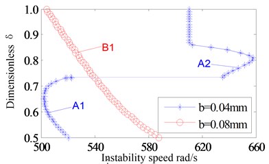
In above analysis, the response characteristics with 0.6 and 0.8 are studied. It can be seen that the instability speed and instability type will change with the changing of rub-impact clearance. The system shows quasi-periodic bifurcation, and has a high instability speed with a large rub-impact clearance (a slight rub-impact, 0.8). When the rub-impact clearance is small (a serious rub-impact, 0.6), the system appears period-doubling bifurcation and has a low instability speed. In order to verify the conclusion, the Floquet theory is used to solve the stable speed. Eccentricity is classified into two categories: 0.04 mm (small eccentricity) and 0.08 mm (large eccentricity). Fig. 7 shows the bifurcation set in rotor/stator clearance and rotating speed parameters plane with the two type eccentricities. It can be seen that the system instability type has changed with the eccentricity 0.04 mm. Set A1 is period-doubling bifurcation. Set A2 is Hopf bifurcation. The results are consistent with the previous analysis. For the Set A1, system instability speed decreases firstly, and then increases with the increasing of rub-impact clearance. For the Set A2, system instability speed increases firstly, and then decreases. When the dimensionless rub-impact clearance 0.87, the rub-impact faults disappear, which makes the instability speed not change. However, when the eccentricity is 0.08 mm, the system appears a period-doubling bifurcation, and the instability speed decreases with the increasing of rub-impact clearance. According to the above results, in bifurcation set of rotor/stator clearance and rotating speed plane, the instability speed and instability type are affected by the eccentry. For different eccentricities, the instability speed and instability type have different characteristics.
Fig. 7The bifurcation set in rotor/stator clearance-rotating speed parameters plane
4. Experimental devices and scheme
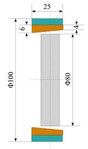
In order to verify the previous theoretical calculation results, based on the dynamic similarity principle, a corresponding test-bed is established. Fig. 8 shows the experimental devices roto-bearing system containing rub-impact faults, the rub-impact fault occurs at the two disks. The experimental scheme is showed as Fig. 8b, the number 1 represents the rub-impact devices, and 2 represents rub-impact monitoring device. Rub-impact device is mounted the location of the two disks. Only the stability and vibration characteristics of the system influenced by rub-impact clearance are considered.
Fig. 8The experimental sketch map of the rub-impact between rotor and stator
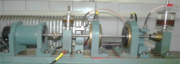
a) Rub-impact test bed
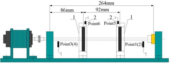
b) Rub-impact experiment device schemes
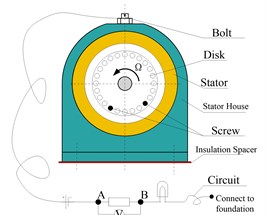
To effectively monitoring rub-impact fault conditions during the operating of experiment device, rub-impact monitoring devices are designed as Fig. 9. One end of the monitoring circuit is switched on any one place of the experimental base; the other side of the circuit is connected to the stator. The rotor and stator are in a loop of the series. Ensure the circuit and the base is insulated during the installing of the rub-impact device. If the disk and stator contact, the circuit will be switch on, the indicator light will shine; if there is not rub-impact phenomenon between disk and stator, the circuit will disconnect, indicator light will not shine. The voltage signal between A and B are gathered into computer by a photoelectric coupler. The indicator lights in the circuit can directly display whether the rub-impact is occurred between rotor and stator or not, and once the signal collected in computer combines with the time domain waveform, it can effectively investigate the rub-impact duration time of the system. As show in Fig. 9c is the monitoring device, and accordingly, the circuit diagram of the rub-impact monitoring device is shown in Fig. d.
Fig. 9The sketch-map of rub-impact and the monitoring device
a) Rub-impact monitoring schemes
b) rotor-stator device
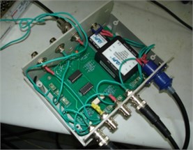
c) Rub-impact fault monitoring device
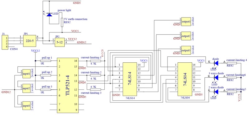
d) The circuit diagram of the rub-impact monitoring device
5. Result analysis of the experiment
Due to the experimental conditions, only qualitative analysis of the influence of system response is studied. In order to ensure that the experiment gets good results, only the stator position can be moved to obtain different rub-impact clearance. In this experiment, only slight rub-impact and serious rub-impact are considered. For the rotor system of slight rubbing, due to the large rub-impact clearance, the phenomenon of rub-impact will happen only when the system reaches to the critical speed or the “oil whip” phenomenon happens.
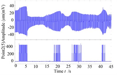
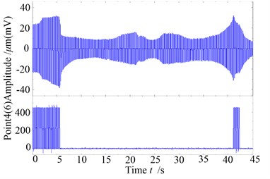
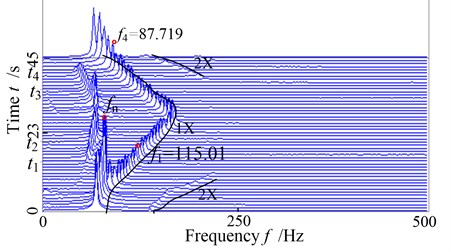
The Fig. 10 is the whole time domain waveform of the rotor system observed with slight rub-impact caused by a large clearance. For the disk on the left side, rub-impact fault happens only when the system reaches to the critical speed and “oil whip” phenomenon happens, meanwhile the rub-impact happens at the right side only when the critical speed happening. Fig. 11 is the 3D spectrum diagram of measure point 2 for rise-and-fall speed satuation, it can be seen from the diagram, a half times rotatinonal frequency appears from moment, which is the common “half speed whirling motion”, it begins to appear “lock frequency” phenomenon until moment. It shows as “oil whip” in this interval, and begins to appear “half speed whirling motion” from moment, until the moment this phenonmenon disappear. It is can be seen that the work frequency 115.04 Hz in the moment and the work frequency 87.719 Hz in the moment appear fractional frequency, i.e. appear instability from period-1 motion, besides, it also shows that the oil whirl of the system appears “hysteresis phenomena”, and the rub-impact fault phenomenon appears when it reaches to the critical speed at commissioning and parking, which makes it appear 2X frequency component in the three dimensional spectral diagram, at other moment, the frequency multiplication can not be found because there has no rub fault or only some slight rub-impact fault happens.
Fig. 10The global time wave plots of the rotor with slight rub-impact
a) Rub-impact response and monitoring on the right disk
b) Rub-impact response and monitoring on the left disk
Fig. 11The global three-dimensional spectrogram of the system with slight rub-impact
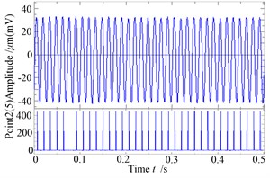
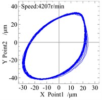
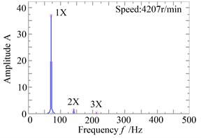
For the satuation of slight rub faults, the Fig. 12a gives the waveform and rub-impact monitoring curve of the system when the speed reaches to 4207 r/min, it can be seen from the figure that the time of rub-impact is much longer, although only 0.5 seconds of response of the system is investigated, this is mainly because the system is close to the critical speed at this moment, and the vibration amplitude of the system is higher, which makes the rub-impact happens. The Fig. 12b/c is the shaft centerline orbit and amplitude spectrum diagram of the right measure point of the system at the moment, from the figures, the orbit diagram is slightly disordered, In addition to the rotating frequency components, the amplitude spectrum diagram apears two 2X rotating frequency component and slight 3X rotating frequency component.
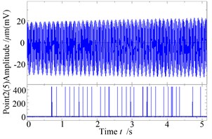
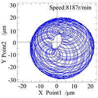
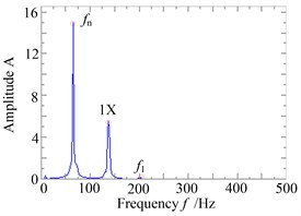
Fig. 13a is the waveform and rub-impact monitoring curve when the speed of the system reaches to 8187 r/min, seen from the diagram, although only 5 seconds of response of the system is investigated, the time of rub-impact is not too many, this is mainly because the system is close to “oil whip”, but the vibration amplitude of the disk on the right side is not enough larger, which makes the rub-impact fault not serious at the moment. The Fig. 13b/c is the shaft centerline orbit and amplitude spectrum diagram of the right measure point of the system at the moment, as it can be seen from the figure, the orbit shows a never repeated curve, which shows that the system is in periodic motion. In addition to one times rotating frequency components, the amplitude spectrum diagram appears frequency component of the first-order critical speed and it appears a combination frequency () but has not multiple frequency. It suggests that the rub-impact fault has not obvious effect on the system, and the system performs as a Hopf bifurcation at this moment.
Fig. 12The response and rub-impact monitoring graph when ω= 441 rad/s
a)
b)
c)
Fig. 13The response and rub-impact monitoring graph when ω= 857 rad/s
a)
b)
c)
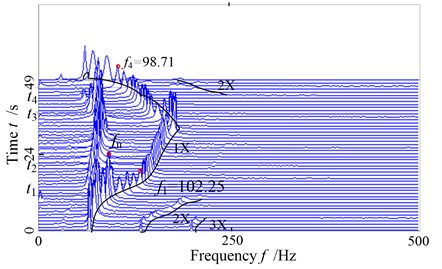
For the rotor system with a serious rub-impact phenomenon, because of small rub-impact clearance, the rub-impact phenomenon has been happening during its rotating. Fig. 14 is the whole time domain waveform of the system. As it can be seen from the diagram, due to the small clearance, the rub-impact fault has been happening at the two disks in the whole increasing-speed and falling-speed stage. The vibration amplitude of “oil whip” is much higher than the ones on the first order critical speed, which shows that the rub-impact fault can make “oil whirl“ and “oil whip“ more serious. The Fig. 15 is the 3D spectrum diagram of measure point 2 in increasing-speed and falling-speed stage, seen from the diagram, due to the rub-impact fault, the acceleration process of the system became slower, but the increasing and falling process are relatively complete. The “half-frequency whirl”, “locking frequency” and “oil whip” phenomenon have also appeared in this processing, but the rotating frequency 102.25Hz at the moment and 98.71 Hz at the moment appear/disappear fractional frequency phenomena, which appear/disappear instability of the period-1 motion; it can be seen from the comparisons to the response of slight rub-impact fault, the instability speed increases because of the rub-impact’s deterioration. Besides, it can be seen from these diagrams, although the rub-impact of the system is serious when the oil whip happens, “oil whip” still accounts for a major position at this moment, there is not frequency multiplication in the spectrum diagram, in the stage of increasing-speed and falling-speed, since the oil whirling and oil whip motion don’t happen, the system is shown as 2X rotating frequency and 3X rotating frequency components. It shows that for a rotor system with no oil “whirling motion” and “oil whip”, if rub-impact fault happens, the frequency multiplication will be more obvious. Otherwise, the rub-impact characteristics of the system aren’t easy to be found in the spectrum diagram.
Fig. 14The global time wave plots of the rotor with serious rub-impact
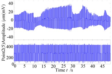
a) Rub-impact response and monitoring on the right disk
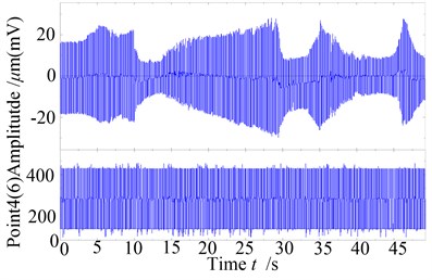
b) Rub-impact response and monitoring on the lsft disk
Fig. 15The global three-dimensional spectrogram of the system with serious rub-impact
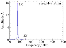
Considering the serious rub-impact, Fig.16 is the waveform and rub-impact monitoring curve when the rotating speed reaches to 4491 r/min, as it can be seen from the diagram that the rub-impact phenomenon is continuous. It is close to the first order critical speed at this moment, which makes the rub-impact more serious. The Fig. 16b/c is the shaft centerline orbit and amplitude spectrum diagram of the right measure point of the rotor system. The orbit diagram becomes irregular, in addition to one times frequency components, and the amplitude spectrum diagram has 2X frequency component, which is caused by rub-impact fault, but the system runs in a stability state.
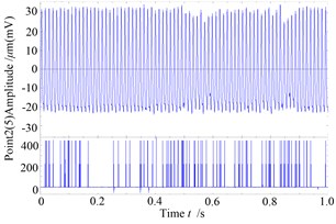
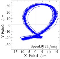
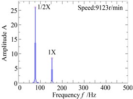
Fig. 17 is the waveform and rub-impact monitoring curve when the speed of the system reaches to 9123 r/min, it shows that the time of rub-impact is long and continous, although only 1 seconds curves is investigated, and there is an obvious “clipping” phenomenon, this is mainly because the “half speed whirling motion” has happened, and it is close to “oil whip”. The Fig. 17b/c is the shaft centerline orbit and amplitude spectrum diagram of the right measure point of the system at this moment, seen from the diagram, the orbit diagram performs as “deformed 8” shape because of the rub-impact faults. In addition to the rotating frequency component, there is 1/2 times frequency components in the amplitude spectrum diagram, and its amplitude is higher than rotating frequency component, but there isn’t 2X frequency component at the moment. This shows although serious rub-impact fault happens, the frequency multiplication components in the spectrum diagram are not shown, whirling motion is the main motion form. Something needs to be explained that although the system is the same, the first critical speed becomes larger with the smaller clearance, this is mainly because the decreased rub-impact clearance constrains the system’s vibration in the two disks places, in other words, it strengthens the constraint of the system, which makes the critical speed increase.
Fig. 16The response and rub-impact monitoring diagram when ω= 470 rad/s
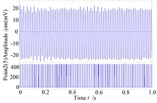
a)
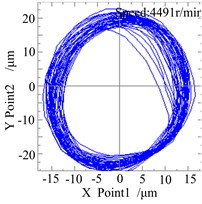
b)
c)
Fig. 17The response and rub-impact monitoring diagram when ω= 955 rad/s
a)
b)
c)
It can be seen from the former experiment results, the design of the rub-impact monitoring circuit has monitored the rub-impact fault effectively. The experiment results show that when the rub-impact clearance decreases i.e. the rub-impact fault gets worse, the instability speed will decrease, but the phenomenon of “oil whirl” and “oil whip” gets more obvious because of the influence of the rub-impact faults, and the multiple frequency components of the frequency domain diagram are not obvious. Comparing the theoretical experiments, the theoretical calculation results is verified: the system shows quasi-periodic bifurcation, and has a high instability speed with a high of rub-impact clearance. When the rub-impact clearance is low, the system appears period-doubling bifurcation and has a low instability speed.
6. Conclusions
It can draw the following conclusions through the former theoretical analysis and experimental results:
(1) When the rub-impact clearance decreases, the instability speed becomes smaller, and shows an instability form of period-doubling. When the rub-impact clearance increases, the instability speed becomes larger, and shows an instability form of quasi-periodic.
(2) When the system in a low speed, the frequency domain appeares frequency multiplicaiton because of the existence of rub-impact fault, but when the system in a higher speed, the multiple frequency component is not obvious because of the strong “whirling motion” or “whip motion”.
(3) The phenomenon “oil whirl” and “oil whip” of the system may become more obvious because of the influence of the rub-impact fault. And the design of the rub-impact monitoring circuit has monitored the rub-impact fault effectively and provided a very effective auxiliary function.
References
-
Muszynska A. Rotor-to-stationary element rub-related vibration phenomena in rotating machinery: Literature survey. The Shock and Vibration Digest, Vol. 21, Issue 3, 1989, p. 3-11.
-
Ehrich F. F. Some observations of chaotic vibration phenomena in high-speed rotor dynamics. ASME Journal of Vibration and Acoustics, Issue 113, 1991, p. 50-57.
-
Ehrich F. F. Observations of subcritical superhamornic and chaotic response in rotor dynamics. Journal of vibration and acoustics, Issue 114, 1992, p. 93-100.
-
Chu F. L., Zhang Z. S., Feng C. P. Chaoyic behavior of a rub rotor model. Journal of Tsinghua Uiversity, Vol. 36, Issue 6, 1996, p. 52-57.
-
Chu F., Zhang Z. Bifurcation and chaos in a rub-impact Jeffcott rotor system. Journal of Sound and Vibration, Vol. 210, Issue 1, 1998, p. 1-18.
-
Lu W. X., Chu F. L. Experimental investigation of rotor rubbing faults. Journal of Tsinghua University, Vol. 45, Issue 5, 2005, p. 614-621.
-
Jun J., HeinzU. Stability analysis of sliding whirl in a nonlinear Jeffcott rotor with cross-coupling stiffness coefficients. Nonlinear Dynamics, Vol. 210, Issue 24, 2001, p. 269-283.
-
Cong F. Y., Chen J., Dong G. G., et al. Experimental validation of impact energy model for the rub–impact assessment in a rotor system. Mechanical Systems and Signal Processing, Vol. 25, Issue 7, 2011, p. 2549-2558.
-
Zhang Y. M., Wen B. C., Andrew Y. T. Leung. Reliability analysis for rotor rubbing. ASME Journal for Vibration and Acoustics, Vol. 124, Issue 1, 2002, p. 58-62.
-
Zhang Y. M., Wen B. C., Liu Q. L. Uncertain responses of rotor-stator systems with rubbing. JSME International Journal Series C: Mechanical Systems, Machine Elements and Manufacturing, Vol. 46, Issue 1, 2003, p. 150-154.
-
Wan C., Jian C., Chen C. K. Chaos and bifurcation of a flexible rub-impact rotor supported by oil film bearings with nonlinear suspension. Mechanism and Machine Theory, Vol. 42, Issue 3, 2007, p. 312-333.
-
Wang C., Lo C., Chen C. Nonlinear dynamic analysis of a flexible rotor supported by externally pressurized porous gas journal bearings. ASME Journal of Tribology, Vol. 124, Issue 3, p. 553-561.
-
Chen C. L., Yau H. T. Chaos in the Imbalance Response of a Flexible Rotor Supported by Oil Film Bearings with Non-Linear Suspension. Nonlinear Dynamics, Vol. 16, Issue 1, 1998, p. 71-90.
-
Gjika K., Andres L. S., et al. Nonlinear Dynamic Behavior of Turbocharger Rotor-Bearing Systems With Hydrodynamic Oil Film and Squeeze Film Damper in Series: Prediction and Experiment. Journal of Computational and Nonlinear Dynamics, Vol. 5, Issue 4, 2010, p. 041006-041008.
-
Chen Y. S.,Meng Q. Bifurcations of a nonlinear rotor-bearing system. Journal of Vibration Engineering, Vol. 9, Issue 3, 1996, p. 266-275.
-
Chen Y. S., Ding Q., Meng Q. Analysis of the instability of low frequency vibration of rotor system. Journal of Applied Mechanics, Vol. 15, Issue 1, 1998, p. 113-117.
-
Ji F., Yang Jinfu, Yuan X. Hopf bifurcation and stability analysis of flexible rotor-bearing system. Journal of Vibroengineering, Vol. 14, Issue 2, 2012, p. 723-733.
-
Khanlo H. M., Ghayour M., Ziaei-rad S. Bearings coefficients effects on chaotic and bifurcation behavior of flexible rotor systems subjected to rub-impact. Journal of Vibroengineering, Vol. 14, Issue 2, 2012, p. 920-930.
-
Xie W. H.,Tang Y. G.,Chen Y. S. Analysis of motion stability of the flexible rotor-bearing system with two unbalanced disks. Journal of Sound and Vibration, Vol. 3, Issue 10, 2008, p. 381-393.
-
Adiletta G., Guido A. R., Rossi C. Nonlinear Dynamics of a Rigid Unbalanced Rotor in Journal Bearings. Part II: Experimental Analysis. Nonlinear Dynamics, Vol. 14, Issue 2, 1997, p. 157-198.
-
MuszynskaA. Improvements in lightly loaded rotor/bearing and rotor/seal models. Journal of Vibration Acoustics – Transactions of the ASME, Vol. 110, Issue 2, 1988, p. 129-136.
-
Gjika K., Andres L. S., Larue G. D. Nonlinear dynamic behavior of turbocharger rotor-bearing systems with hydrodynamic oil film and squeeze film damper in series: prediction and experiment. Journal of Computational and Nonlinear Dynamics, Vol. 5, Issue 4, 2010, p. 0410061-0410068.
About this article
The project was supported by China Natural Science Funds (No. 51105063) and the Fundamental Research Funds for the Central Universities (No. N120403004).
