Abstract
In the process of drilling coal, the kinematics of drill-rod is quite complicated. The drill-rod not only vibrates in longitudinal, transverse and torsional direction, but also random impacts and contacts coal wall. Considering the drilling load of drill-bit and coal, contact impact of the drill-rod and coal wall, the drill-rods are dispersed into a number of finite elements. At the same time, the nonlinear dynamic model of drill-rod system coupling longitudinal, transverse and torsional vibration is set up. The simulations of the dynamic model are researched under the conditions of different hardness coal (2.7, 3.7, 4.65). In order to decrease the vibration of auger drill, the stabilizer is added onto the drilling mechanism. And the underground experiments are done at 2404 working face of Xie-Zhang Coal Mine in Shan-Dong Province of China. The results indicate that the transverse vibration radius, the longitudinal vibration frequency and amplitude all decrease with the rock hardness. The maximum transverse vibration radius shows an exponential relation with the drilling depth under the condition of the same rock. Under the same condition, the drilling depth of auger drill with stabilizer is 1.39 times that with no stabilizer, and the drilling pressure decreases about 2/3.
1. Introduction
The drilling system often deviates from the set direction, which caused by the vibration in drilling. Drilling system vibration of auger drill results in a deteriorated drilling performance. Field experience reveals that it is crucial to understand the complex vibrational mechanisms of a drilling system in order to better control its functional operation and improve its performance. There is little material or literature about the auger drill for it’s a new machine used in extremely thin coal seam. But a lot of researches are done about the vibration characteristics of drilling system of other machines similar with auger drill, which can be as a reference for this research.
The vibration coupling the longitudinal and transverse of drill-rod based on the Hertz contact theory was researched and the coupling vibration dynamics model was built [1-3]. A non-linear dynamic inversion control design method was raised to suppress the transverse and the torsional vibrations of a non-linear drill-rod, which reduced the vibration significantly [4]. A dynamic model of the drill-rod including both drillpipe and drillcollars was formulated in which considered the gyroscopic effect, the torsional/bending inertia coupling, and the effect of the gravitational force field [5-6]. Through multivariate linear regression analysis and sensitivity analysis, a model was developed to determine which factor had the greatest effect on surface heave development with horizontal directional drilling, the result indicated that the relationship between surface heave and drilling practice was not a linear relationship, but a dynamic system where changed in factors produce nonlinear responses [7]. The geometrical stiffening of the drill-rod using a non-linear finite element approximation was analyzed, in which large rotations and non-linear strain-displacements were taken into account [8]. The operation recommendations and the detection of safe drilling parameters in a conventional oil well drill-rod was presented by using dynamical analysis tools, which took into account the fact that the drill-rod length increased as drilling operation and analyzed the reasons of the sliding motion giving rise to self-excited drill-bit stick-slip oscillations and drill-bit sticking phenomena at the bottom-hole assembly [9]. A stochastic computational model was proposed to model uncertainties in the bit-rock interaction system and the non-linear dynamical equations were discretized by means of the finite element method [10]. The drill-rod vibrations with differential quadrature method were analyzed, which indicated the method was efficiency and accuracy in dealing with drill-rod vibration problems [11]. Using the perturbation techniques, the nonlinear model for a drill-rod system in deviated well with axially moving motion and axial loading was developed, and the effects of rotating speed, axial compression load, imbalance mass and nonlinear fluid force on the drill-rod responses were investigated in detail, nonlinear natural frequencies and their corresponding mode shapes were presented [12]. The problems on investigation of the dynamic bending of elongated drill-rod tubes was considered, which indicated that the free bending vibrations of unbounded rods could be realized only in the modes of regular dextral and sinistral spiral waves propagating with different velocities in different directions [13]. A method for controlling the torsional and stick-slip vibrations by exactly decomposing the drill string dynamics into two traveling waves traveling in the direction of the top drive and in the direction of the drill-bit was presented [14]. A new method named “time history shape function method” was developed to study the dynamic boundary condition between the revolving drill-rod and borehole wall, which proved the method was accurate and reasonable [15]. The nonlinear dynamic model of drilling system coupling longitudinal, transverse and torsional vibration was built to study the numerical method of high nonlinear dynamic model [16-17].
The above researches provide the references for this study. But the vibration of the Coal-Drillrod-Drillbit interacted system under the conditions of different hardness coal and different rotary speeds has not been researched. In order to master the vibration actions of the drilling system and improve the drilling efficiency, the coupling vibration of drilling system is researched in this paper. For the complexity of coupling system, the coupling system is simplified and assumed, and the interacted dynamics models between drill-rod and coal, drill-bit and coal are built respectively. And then, the models are solved according to the contact collision condition between drill-rod and coal. The coupling vibration simulations of drilling system are done basing on the experiment data, which will provide technical support for improving drilling performance and predicting motion trail of drilling system.
2. Coupling nonlinear dynamics model of interacted system
2.1. Basic hypothesis
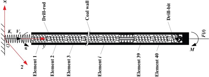
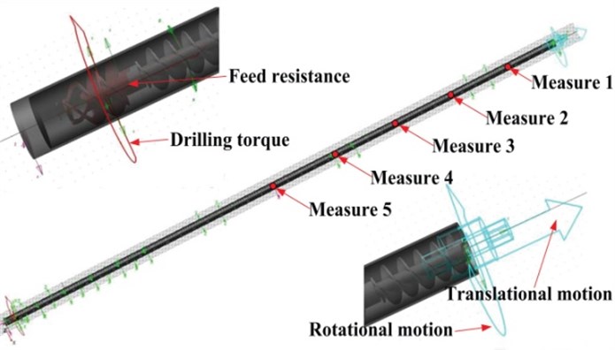
The coal drilling broken is a dynamic process, and the drilling system will be influenced by the gravity, feed resistance, resistance torque, damping, impacting force and frictional resistance between drill-rod and coal wall. Under these external forces, there is not only longitudinal, transverse and torsional vibrations, but also coupling vibration existing in the collision between drill-rod and coal wall. The collision force is a random variable changing with the time. The drilling system is taken as the researched object, shown in Fig. 1. Where is axial feed speed of drill-bit, is the resistance torque acted on drill-bit, is longitudinal force of drill-bit, is rotary speed of drill-bit.
The basis hypothesis as follows:
(a) The cross-section of drilling hole is round, and the diameter of drilling hole is not changed with the time.
(b) The drill-bit is rigid, and the drill-rod is elastomeric. The original axis of drill-rod is coincident with the axis of drilled hole, and the drill-rod axis can deviate from the original axis when drilling coal.
(c) The collision happened between drill-rod and coal wall is multi-directional and random. The drilling pressure is a constant along the drilling hole axis.
(d) The transverse vibration is researched through decomposing two component and on the cross-section.
(e) The friction force between the drill-rod and the broken coal is not considered, and the connection between drill-rod and driver motor is simplified as a spring with the stiffness .
Fig. 1Discretization of drilling system
2.2. Coupling nonlinear dynamics model
The drill-rod is highly nonlinear, and there is friction between drill-rod and coal wall. So the analytic solution of the continuous drill-rod system cannot be acquired. The drill-rod is dispersed into a number of elements, and transferred to a multi-degree system. The drill-rod is connected together by a spring and damping. The rotational inertia of drill-bit is . And the rotational inertia of each drill-rod is . The parameters of drill-rod are given in Table 1.
Table 1Parameters of drilling system
Parameter | Value |
Length | 48.2 m |
Rotational inertia | 10.79 kg·m2 |
Damping | 0.001 N·s |
Polar moment | 1.884·10−5 m4 |
Shear modulus | 7.96·109 N/m2 |
Density | 7801 kg/m3 |
The vibration equation of drilling system as follows [14]:
where is mass matrix of drilling system, is damping matrix of drilling system, is stiffness matrix of drilling system, , and are acceleration, speed and displacement vector of drilling system, is equivalent external load vector, , and .
The expressions of the rotational inertia , damping and connecting stiffness are shown as follows:
Taking the interacted load between drill-bit and coal as the boundary condition, the coupling nonlinear dynamics model can be acquired according to the mass matrix, damping matrix and stiffness matrix of drilling system.
2.3. Interacted load model of drill-bit and coal
In the drilling process, the drill-bit is influenced by the feed resistance, transverse force and resistance torque. The longitudinal load of drill-bit is composed of the drilling pressure, the reacting force of the coal and the dynamic load of drill-bit. And all of these forces should be balanced at any time when drilling. So the longitudinal mechanical model of drill-bit and coal is shown in equation (8):
where is the drilling pressure of drill-bit at any time, is mass of drill-bit, is acceleration of drill-bit at any time, is longitudinal force of drill-bit at any time.
The transverse force of drill-bit endured is a resultant, which is computed through decomposing into two forces along -coordinate and -coordinate:
where is transverse force of drill-bit, is the drilling angle of the -th pick at time .
In order to ensure the stability of drilling, the resistance torque of drill-bit should be equivalent with the drive torque. If the coordinate of -th pick at time is , the resistance torque acted on drill-bit is:
where is the distance between the pick tip and the axis, is the distance between the pick tip and the axis in the coordinate system of drill-bit, and are components of the transverse forces decomposed into the and axis respectively.
2.4. Contact collision conditions and dynamic model solution
2.4.1. Contact collision conditions of drill-rod and coal wall
The energy of drill-rod will be lost because of the friction between drill-rod and coal wall in drilling process. According to the energy conservation law and ignoring the lost of thermal energy, the lost energy of drill-rod will be transferred to the elastic deformation energy and the kinetic energy of coal wall. Due to the randomness and multi-directionality of the collision between drill-rod and coal wall, it is difficult to describe the motion law of drill-rod exactly. So the dynamic gap element is introduced between the discretized drill-rod and coal wall, which is a virtual element. The inner boundary of dynamic gap element connects with the outside surface of drill-rod, and outside boundary of dynamic gap element is coincident with the coal wall (Fig. 2a). The motion of drill-rod is not influenced when there is no collision between the drill-rod and the coal wall (Fig. 2b), and the motion of drill-rod will be prevented when the collision happens (Fig. 2c). A certain deformation energy will be stored after the dynamic gap element deforms, which can be used to describe the energy lost in colliding process [18].
Fig. 2Collision between drill-rod and coal wall
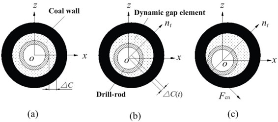
If the initial gap between drill-rod and coal wall is , the normal relative displacement between drill-rod along the direction and the normal of coal wall is at time , the contact point tangential speed of drill-rod and coal wall is , the maximum elastic deformation of coal wall is , the judging conditions of collision between drill-rod and coal wall are shown as follows.
Freedom state:
Collision state:
where indicates that the friction along the circumference of drill-rod is rolling friction, indicates that the friction is sliding friction. But the friction along the axis of drill-rod is always sliding friction.
The elastic modulus of coal-wall is related with the hole depth, coal characteristics, drilling speed, drilling acceleration and time. Due to the inaccuracy of the variables, the transversal displacement of drill-rod will exceed the drilled hole wall in simulation. So the elastic modulus of dynamic gap element needs to be revised until satisfy the conditions of convergence, shown as follows.
Freedom state:
Collision state:
where and are infinitely small quantities greater than zero, is normal reaction force on dynamic gap element at time .
The contact collision state between drill-rod and coal wall is divided into two kinds according to contact time: continuous contact collision and intermittent contact collision. Continuous contact collision easily happens between the elements far to the end of drill-rod and coal wall, and intermittent contact collision easily happens between the elements near to the end of drill-rod and coal wall. The elements happened intermittent contact collision with coal wall rebound, which makes the conditions of collision between drill-rod and coal wall not satisfied. And the elements will stay in the freedom state until that the conditions of collision between drill-rod and coal wall was satisfied. It might also be noted that the discription of contact collision process will be more fine through decreasing the time step when adopting the dynamic gap element method.
2.4.2. Dynamic model solution
In order to acquire the solution of Eq. (1), the Houbolt method is utilized. Supposing the third-order approximate solution can be used to express the value of in the scope of , the value of can be obtained by twice differential, and the values of and can be got respectively through one integral and twice integral from to . The solution of Eq. (1) is shown in Eq. (15):
3. Coupling vibration simulation
According to the previous experiment data and field experience, the compression strength of the artificial coal is 2.5 times the natural coal [19]. Because the artificial coal is homogeneous while there are bedding and joint in natural coal. The compression strengths of artificial coal in this experiment are 18.6 MPa, 14.775 MPa and 10.725 MPa. So they are equivalent to the natural coal with compression strength of 46.5 MPa ( 4.65), 36.9375 MPa ( 3.7) and 26.8125 MPa ( 2.7). Where is the Proctor coefficient of coal, which is also known as the rock solid coefficient and fastening coefficient and its value is 1/100 of the limit of the rock uniaxial compressive strength. The experiments are done on the rock & coal cutting test bed [20], the drill-bit rotary speed is 60 rev/min, and the drilling feed speed is 1 m/min. The drilling torque and resistance force are shown in Fig. 3 and Fig. 4.
According to the theory above, the interacted system coupling dynamic simulations of the drilling mechanism and coal are done by ADAMS. Simulation conditions: drilling hole depth is 40 m, rotary speed of drill-bit is 60 rev/min, diameter of drill-bit is 550 mm, length of drill-bit is 770 mm, diameter of drill-rod is 450 mm, length of drill-rod is 48.2 m. The constraints of drilling mechanism are set in ADAMS, and the drill-rod is replaced with a flexibility body. The contact between the flexible drill-rod and coal wall is set, too. The rotary driver and line driver are added on the end of drill-rod, and the torque resistance and feed resistance acquired from the experiments are added on the drill-bit. The dynamic model of interacted system is shown in Fig. 5. Under the conditions of different coal compression strength and different rotary speed, the coupling dynamic simulation is done. The simulation time is 10 seconds, and the simulation steps are 600.
Fig. 3Drilling torque of different coal
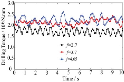
Fig. 4Feed resistance force of different coal
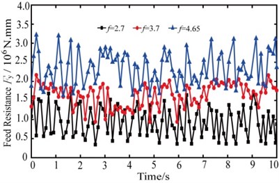
Fig. 5Dynamics simulation model of interacted system
3.1. Vibration of drill-rod when 4.65
The motion trails of measure points (1, 2, 3, 4, 5) are shown in Fig. 6a~Fig. 6e. The distance between the measure points and the end of drill-rod are 4 m, 8 m, 12 m, 16 m and 20 m. In order to compare the motion trails of each measure point on the cross-section, the simulation data is input to statistical analysis. The vibration circle takes the initial position of measure points as the center of circle, and takes the maximum vibration displacement of measure points as radius. Then the mean and the variance of the vibration amplitude are acquired, which are shown in Figs. 6 and 7.
Fig. 6Motion trails of different measure points on x-z cross-section
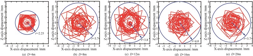
According to the Figs. 6 and 7, the maximum radius shows an exponential relation with the changing of drilling depth. The transverse vibration amplitude of measure point 1 is the minimum. It will enhance if the drilling depth increases, which even resulting in the drill-rod colliding the coal wall. And the variance of measure point 3 is the maximum, which indicates that the collision between drill-rod and coal wall is serious.
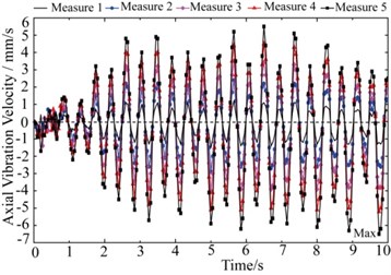
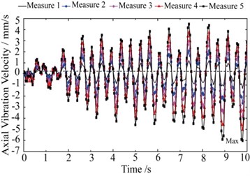
It can be seen from Fig. 8 that the axial vibration tendency of measure points is consistent. The vibration amplitude increases with the drilling depth, and the biggest vibration amplitude is 6.474 mm/s.
Fig. 7Radius statistics of measure points
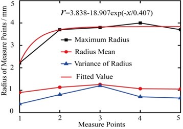
Fig. 8Axial vibration velocity of measure points
3.2. Vibration of drill-rod when 3.7
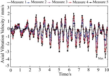
According to the Fig. 9, the relationship between the biggest vibration radius and the drilling depth is approximately exponential. The transverse vibration amplitude of measure point 1 is the minimum. The change of the mean and variance of vibration radius is relatively slow, which indicates that the collision between drill-rod and coal wall is little. Comparing the Fig. 10 with the Fig. 8, it can be known that the axis vibration frequency is decreased, and the biggest vibration amplitude reduces to 5.243 mm/s.
Fig. 9Radius statistics of measure points
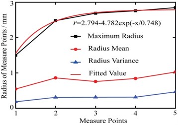
Fig. 10Axial vibration velocity of measure points
3.3. Vibration of drill-rod when 2.7
It can be seen from the Fig. 11, the biggest vibration radius increases exponentially with the drilling depth. And the growth rate of vibration radius is faster, which indicates that the transverse vibration amplitude of measure points increases rapidly, and the serious collision happens at point 5.
The Fig. 12 shows the axial vibration velocity of the drill-rod. Comparing with the Fig. 8 and the Fig. 10, the axial vibration frequency is the smallest, and the maximum amplitude of axial velocity reduces to 3.785 mm/s.
Fig. 11Radius statistics of measure points
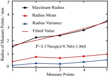
Fig. 12Axial vibration velocity of measure points
From Fig. 7 and Fig. 9, when are 4.65 and 3.7, the mutation of Measure 2 maximum radius comparing Measure 1 is great. And the mutation value is 1-1.5 mm. But there is not large difference in maximum radius between Measure 3, 4, 5 and Measure 2. Moreover, the mutation of Measure 1 under 4.65 is much bigger than that under 3.7. Thus, stabilizers shoud be added on the drill-rods per 4 meters and 8 meters under 4.65 and 3.7 repectively to avoid great vibration. From Fig. 11, when is 2.7, it is the maximum radius of Measure 3, not Measure 2, is 1 mm more than Measure 1. Thus, stabilizers shoud be adopt on the drill-rods per 12 meters under 2.7. In brief, stabilizers added under large hardness should be much more than that under small hardness.
4. Underground experiment of auger drill
According to the above analysis, the vibration of drill-rod increases with the drilling depth. In order to decrease the vibration of drill-rod, the method of adding stabilizer is proposed shown in Fig. 13 and Fig. 14.
Fig. 13Structure of auger drill
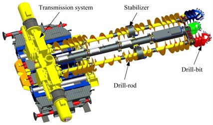
Fig. 14Structure of stabilizer
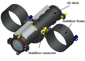
From Fig 14, the stabilizer is mainly consisting of stabilizer frame and stabilizer connector, and the stabilizer frame is rigidly connected at the air duck through stabilizer connector. The diameter of stabilizer frame is 20~30 mm bigger than the diameter of drill-rod. The width of stabilizer frame is about 0.6 times the diameter of stabilizer frame.
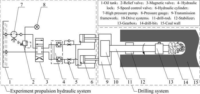
The drilling experiment is done on the 2404 working face of Xie-Zhuang Coal Mine in Shan-Dong Province of China. Where the incline angle of coal seam is 8º, the Proctor coefficient of coal seam is 2.5, thickness of coal seam is 0.6-0.8 m. And the mechanical parameters of auger drill are shown in Table 2. The structure and working principle of the experiment system are shown in Fig. 15. The experiment system comprises an experiment propulsion hydraulic system and a drilling system. The composition and working principle of each subsystem are as follows:
(1) The experiment propulsion hydraulic system which is developed by the authors mainly consists of oil tank, high pressure pump: 16 MPa, rated flow: 100 L/min, made in China, used for providing the pressure source for propulsion system, relief valve, pressure gauge, magnetic valve, hydraulic lock, speed control valve, and hydraulic cylinder and so on. The hydraulic oil arrives to the hydraulic cylinder through the magnetic valve, the hydraulic lock and the speed control valve, which provides a propulsion power for the drilling system. Where the hydraulic lock is used to prevent the hydraulic cylinder declining under the feed resistance, the speed control valve is used to regulate the speed of the hydraulic cylinder, and the relief valve is used to produce a back-pressure and prevent system overload.
(2) The drilling system mainly includes transmission framework, drive system (drive motors: 2×110 kW, made in China, used for providing power for the mechanical drilling, gear reducer and hydraulic coupler), drill-rod, drill-bit (mechanical parameters are shown in Table 2), stabilizer and gearbox and so on. When the system starts working, the drive motors driving drill-bits cutting the coal wall through the drill-rods and gearbox, and the hydraulic cylinder push forward the drilling mechanism to complete drilling the coal wall.
Table 2Mechanical parameters of auger drill
Drilling power | 2×110 kW |
Diameter of drill-bit | 550 mm, 425 mm |
Numbers of drill-bit | 3 |
Diameter of drill-rod | 480 mm |
Length of drill-rod | 1500 mm |
Rated operational voltage | Three phases AC 660 V |
Feed speed | 0~1 m/min |
Rotary speed | 60 rev/min |
Fig. 15Structure and working principle of the experiment system
Before the experiments, the roadway roof must be supported stably and the auger drill must be fastened. The drilling depth is measured through the numbers of drill-rods, and the drilling pressure of auger drill is taken as the criterion to judge the deflection of drill-rods from the pressure gauge in Fig. 14. The experiments are divided into four groups, in the first three groups, the stabilizers are added on the drill-rods per 4 meters, 6 meters, and 8 meters, and the fourth group works without stabilizer. Four groups of drilling experiments are conducted, and the drilling depth and the drilling pressure obtained are shown in Fig. 16.
Fig. 16Drilling pressure of drill-rod with stabilizer and no stabilizer
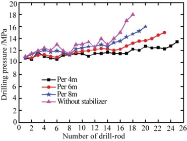
It can be seen from Fig. 16 the drilling pressure increases with the number of drill-rod, the upward trends of the first three groups cruves are consistent, and the fourth group cruve increases greatly after 14 drill-rods, and the drilling pressure of the fourth group is the largest and the drilling depth is the smallest. For the further analysis, the drilling depth and drilling pressure increment of the experiment are obtained, shown in Table 3. It can be seen that the drilling depth reduces from 37.5 m to 27 m, and the drilling pressure increment increases from 2.5 MPa to 7 MPa. Field experience reveals that the deflection is large if the drilling pressure increases quickly, conversely the deflection is small. The experiment shows that the drilling depth of auger drill with stabilizer is 1.39 times that with no stabilizer and the drilling pressure increment decreases 2/3, and the closer of stabilizer interval, the better of effect, but for better economic, the stabilizers are added on the drill-rods per 4 meters in the actual drilling process. The experiment confirms that the method of adding stabilizer is correct and effective.
Table 3Drilling depth and drilling pressure increment of the experiment
Item | Group 1 | Group 2 | Group 3 | Group 4 |
Drilling depth | 37.5 m | 34.5 m | 30 m | 27 m |
Drilling pressure increment | 2.5 MPa | 4 MPa | 5 MPa | 7 MPa |
5. Conclusions
(1) Taking the system of Coal – Drill-rod – Drill-bit as the researched object, considering the collision conditions of drill-rod and rock, the interacted system coupling dynamics model of drilling mechanism and rock is built. Combining with the experimental data, the dynamics model is solved by ADAMS, and the vibration coupled the longitudinal, transverse and torsional of the drill-rod is acquired under different compression strength rock and different rotary speeds of drill.
(2) The deflection of drill-rod is caused by the complexity of coal, the nonhomogeneity of interacted force between drill-bit and coal. With the decrease of coal compression strength, the transverse vibration radius is reduced; the longitudinal vibration frequency and amplitude are all reduced, too. For the same coal, the biggest vibration radius of drill-rod shows exponentially growth with the drilling depth.
(3) The method of adding stabilizer is proposed. At the same condition, the drilled depth of auger drill with stabilizer is 1.39 times than that with no stabilizer. The drilling pressure increment decreases 2/3, and the closer of stabilizer interval, the better of effect, which provides an effective method to prevent deflection of auger drill.
References
-
Yigit A. S., Christoforou A. P. Coupled axial and transverse vibrations of oilwell drillstrings. Journal of Sound and Vibration, Vol. 195, Issue 4, 1996, p. 617-627.
-
Yigit A. S., Christoforou A. P. Coupled torsional and bending vibrations of drillstrings subject to impact with friction. Journal of Sound and Vibration, Vol. 215, Issue 1, 1998, p. 167-181.
-
Christoforou A. P., Yigit A. S. Fully coupled vibrations of actively controlled drillstrings. Journal of Sound and Vibration, Vol. 267, 2003, p. 1029-1045.
-
Al-Hiddabi S. A., Samanta B., Seibi A. Non-linear control of torsional and bending vibrations of oilwell drillstrings. Journal of Sound and Vibration, Vol. 265, 2003, p. 401-415.
-
Khulief Y. A., Al-Naserb H. Finite element dynamic analysis of drillstrings. Finite Elements in Analysis and Design, Vol. 41, 2005, p. 1270-1288.
-
Khulief Y. A., Al-Sulaiman F. A., Bashmal S. Vibration analysis of drillstrings with self-excited stick–slip oscillations. Journal of Sound and Vibration, Vol. 299, 2007, p. 540-558.
-
Lueke Jason S., Ariaratnam Samuel T. Numerical characterization of surface heave associated with horizontal directional drilling. Tunnelling and Underground Space Technology, Vol. 21, 2006, p. 106-117.
-
Sampaio R., Piovan M. T., VeneroLozano G. Coupled axial/torsional vibrations of drill-strings by means of non-linear model. Mechanics Research Communications, Vol. 34, 2007, p. 497-502.
-
Navarro-Lopez Eva M., Cortes Domingo. Avoiding harmful oscillations in a drillstring through dynamical analysis. Journal of Sound and Vibration, Vol. 307, 2007, p. 152-171.
-
Rittoa T. G., Soizeb C., Sampaioa R. Non-linear dynamics of a drill-string with uncertain model of the bit–rock interaction. International Journal of Non-Linear Mechanics, Vol. 44, 2009, p. 865-876.
-
Hakimi H., Moradi S. Drillstring vibration analysis using differential quadrature method. Journal of Petroleum Science and Engineering, Vol. 70, 2010, p. 235-242.
-
Sahebkar S. M., Ghazavi M. R., Khadem S. E., Ghayesh M. H. Nonlinear vibration analysis of an axially moving drillstring system with time dependent axial load and axial velocity in inclined well. Mechanism and Machine Theory, Vol. 46, 2011, p. 743-760.
-
Gulyayev V. I., Borshch O. I. Free vibrations of drill strings in hyper deep vertical bore-wells. Journal of Petroleum Science and Engineering, Vol. 78, 2011, p. 759-764.
-
Kreuzer E., Steidl M. Controlling torsional vibrations of drill strings via decomposition of traveling waves. Arhive of Applied Mechanics, Vol. 82, 2012, p. 515-731.
-
Zhu Xiaohua, Tong Hua, Liu Qingyou, Feng Linxian. Research on the dynamic boundary condition between revolving drill string and borehole wall. China Mechanic Engineering, Vol. 18, Issue 15, 2007, p. 1833-1837, (in Chinese).
-
Zhu Caichao, Feng Daihui, Lu Bo, Yang Yingxin. Nonlinear study on dynamic action of integrated drill string-well rock system. Chinese Journal of Mechanical Engineering, Vol. 43, Issue 5, 2007, p. 145-149, (in Chinese).
-
Zhu Caichao, Song Chaosheng, Wang Qingfeng. Nonlinear stability analysis for helical buckling of drill string in wellbore. Journal of Southwest Petroleum University (Science & Technology Edition), Vol. 32, Issue 2, 2010, p. 1159-1163, (in Chinese).
-
Su Hua, Wang Guangyuan, Zhang Xuehong. Dynamic gap element method for contact-impact problem between slender rod and wall of a round hole. Earthquake Engineering and Engineering Vibration, Vol. 16, Issue 1, 1996, p. 79-86, (in Chinese).
-
Xu Xiaohe. Rock Crushing Theory. Beijing, Coal Industry Press, 1984, (in Chinese).
-
Liu Songyong, Du Changlong, Cui Xinxia. Research on the cutting force of a pick. Mining Science and Technology, Vol. 19, Issue 4, 2009, p. 514-517.
About this article
This Project is supported by Technology Research and Development Program of China (863 Program) (No. 2012AA062102), the Fundamental Research Funds for the Central Universities (Project No. 2012QNA22) and the Priority Academic Program Development of Jiangsu Higher Education Institutions.
