Abstract
The movement characteristics of a rolling-damper isolation system were analyzed to obtain a numerical analysis approach. Computer programs were compiled to analyze the influence of factors such as rolling friction coefficients and damping constants on the earthquake response of the isolation system. The rolling friction and the damper can efficiently decrease the relative displacement of the isolation system, and can considerably increase the acceleration of the isolation system. However, they cannot regularly affect the residual displacement of the isolation system. Therefore, when subjected to design earthquakes, it is desired to obtain a reasonable combination of damper and rolling friction that can decrease the relative displacement of the isolation system to the best while keep the acceleration of the isolation system in an allowable range. This paper provides suggestions on the optimized combination of damper and rolling friction for seismic design of isolation systems.
1. Introduction
Seismic damage has been commonly observed in general structures such as buildings and bridges [1-4]. Isolation devices have been considered as an effective method to mitigate the seismic damage and thus are widely used all over the world. However, there are limitations for the traditional isolation devices, e.g. laminated rubber bearing and lead rubber bearing. When the actual earthquake differs from the design earthquake, which is true for most of the cases, traditional isolation devices may cause a significant deformation and transmit a large force to the isolation structure. Therefore, seismic damage still appears in the isolation structure and even sympathetic vibration may happen [5].
To improve the isolation performance, many researchers have paid attention to the rolling-based isolation methods. In India, Jangid and Londhe developed a theoretical formulation to obtain seismic responses of a multistory building supported by elliptical rolling rods in 1998, which were quite effective in reducing the seismic response of the system without undergoing large base displacements [6]. In 2000, Jangid investigated the stochastic response to the earthquake motion of flexible multi-storey shear type buildings isolated by rolling rods with a re-centering device, indicating that the rolling rods were quite effective in reducing the stochastic response of the structure against the earthquake excitation [7]. In USA, George C. Lee proposed a roller seismic isolation bearing for use in highway bridges in 2010, which utilized a rolling mechanism to achieve the seismic isolation and had a zero post-elastic stiffness under horizontal ground motions, a self-centering capability, and unique friction devices for supplemental energy dissipation. After investigating seismic behaviors of the proposed bearing through parametric studies, George C. Lee suspected there were something wrong with the calculation method in AASHTO Specifications and suggested further investigations [8, 9]. In Portugal, Luís Guerreiro carried out a seismic test and a numerical modeling of a rolling-ball isolation system to protect some light structures in 2007, and the results showed an effective reduction of the acceleration levels induced in the isolation structures [10]. In Japan, Kurita developed a new device for seismic response reduction, and the peak acceleration amplitude was decreased by about 50-90 % [11]. In UK, Monfared investigated many base isolation systems from the historical evidences up to 2012, which presented a comparative perspective of different methods based on their compatibility, efficiency, benefits and weaknesses of each base isolation system, and the results showed that the effectiveness of a base-isolated system depended on the characteristics of the input excitations as well as the properties of the isolation devices and the superstructure [12]. Also in 2012, Nanda in India considered that the base isolation in the form of pure friction (P-F), among all other isolation methods developed so far, was the simplest one, which could be easily applied to low cost brick masonry buildings. Furthermore, the P-F isolation was one of the best alternatives for reducing earthquake energy transmission to superstructure during strong earthquake [13].
In all these studies, the seismic force of structure was controlled as a small value by setting the rolling-friction isolation device, which was usually the friction force. In 2012, Wei Biao presented a calculation method of a pure-rolling isolation system, and obtained the optimum performance for isolation [14-16]. However, the relative displacement was large. Therefore, restoring-force devices, e.g. spring or sloping surface, were considered to add to the pure-rolling isolation device, which could decrease the relative displacement and the residual displacement of the isolation structure. However, if the ratio of the restoring-force device to the pure-rolling device isn’t reasonable, there will be some limitations as well as the traditional isolation devices. On the other hand, as the damper can decrease the relative displacement and have no natural vibration period, it is worth studying to improve the isolation performance instead of adding the restoring-force devices.
With a rolling-damper isolation system as the object of study, a numerical analysis method is advanced based on its movement characteristics. And then a computer program is compiled to analyze the influence of rolling friction coefficients, damping constants and other factors on the performance of the isolation system.
2. Movement characteristics
The movement characteristics of a roller-footing isolated single-pier system are analyzed in this section. As shown in Figure 1, the rolling ball isolates the horizontal earthquake besides supporting the structure. Moreover, it transmits a friction force besides dissipating the earthquake energy. Similarly, the oil damper, which has the linear dependence between the damping force and the relative velocity, transmits a damping force besides dissipating the earthquake energy.
Fig. 1A rolling-damper isolation system
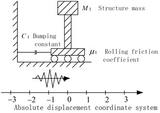
Although the rolling ball and the damper can all dissipate the earthquake energy, there are remarkable differences between the two devices:
(1) The damping force offered by the damper is related to the relative velocity.
(2) The friction force offered by the rolling ball is related to the structural mass, the rolling friction coefficient, and the relative motion or the tendency of relative motion between the structure and the ground.
Moreover, the damper and the rolling ball don’t offer the horizontal stiffness, therefore, the force-displacement relationship of the isolation system is not determined, and the isolation system doesn’t have the natural vibration period. In theory, no matter what earthquake happens, sympathetic vibration does not appear.
Noted that shear keys are needed to meet the normal requirement and their failure is only allowed under large earthquakes. This paper mainly studies the performance of the rolling-damper isolation system after the failure of shear keys.
3. Mathematical model and computer program
3.1. The mathematical model
The seismic response of the rolling-damper isolation system is very complex, as the ground and the structure are both moving. In order to describe the motion of the ground and structure in math expressions, the absolute displacement coordinate system is defined in Figure 1. Moreover, , , are defined as the acceleration, the absolute velocity and the absolute displacement of the ground, respectively. In the same manner, , , are defined accordingly for the structure.
Based on the balance between and , the seismic response of the rolling-damper isolation system is categorized into three cases:
(1) indicates that the relative motion appears between the structure and the ground. The force acting on the structure is .
(2) indicates that the relative motion appears between the structure and the ground. The force acting on the structure is .
(3) indicates that the relative motion doesn’t appear between the structure and the ground. There are two phenomena for it: i) the structure and the ground are all immobile, which usually exists when the earthquake just starts; and ii) the structure and the ground are both moving, and sometimes they have the same absolute velocity. However, the two phenomena are only superficies. In order to forecast the next motion of the structure, it is necessary to compare and :
(a) When , the structure subjected to the inertia force doesn’t move relative to the ground, and the structure acceleration is equal to the ground acceleration .
(b) When , the structure subjected to the inertia force moves relative to the ground. The force acting on the structure is , in which the sign depends on the direction of the ground acceleration .
In summary, the motion states are divided to the rolling state and the non-rolling state. The former including three cases of (1), (2) and (3) (b), and the latter only includes the case of (3) (a). They are calculated as following:
(1) When the rolling state is concerned, the isolation structure is subjected to the force of Based on the Euler-Gauss method, the relationship between the structural acceleration, the structural velocity and the structural displacement can be easily obtained. Finally, the structural movement of the next time can be calculated based on that of the previous time.
(2) As for the non-rolling state, the structure moves along with the ground. The acceleration, the velocity and the displacement increment of the structure are the same as those of the ground motion, which can be easily obtained.
Moreover, the transforming relationship between the rolling state and the non-rolling state is shown as following:
(1) For the case of or : when and , next time the structure will move along with the ground, i.e. , where and is the time of the ground motion input.
(2) For the case of : when , next time the structure will move relative to the ground, i.e. or .
3.2. Computer program
Based on the mathematical model, the computer program is compiled by Tcl/Tk language according to the computer block diagram in Figure 2. The computer program is an independent program to calculate the seismic response of the rolling-damper isolation system.
The computer program is composite of five modules, including building the structure model, inputting the ground motion, calculating the rolling state, calculating the non-rolling state and recording the calculation results. After the validation by a model test [14], the computer program is used to analyze the seismic performance of the rolling-damper isolation system in the following sections.
4. Numerical calculation
4.1. The structural model
The structure in Figure 1 is analyzed by the computer program in Figure 2. The structural model is built as one rigid body since the stiffness of the isolation device is much less than the stiffness of the structure [5], and the structural mass is set to be 300 t. The damping constants adopt 0, 100, 200, 300, 400 and 500 kN·s/m, respectively. The rolling friction coefficients adopt 0.002~0.030, and the interval is 0.002.
Fig. 2Calculation procedure of the seismic response
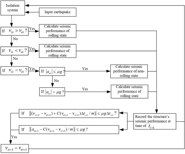
Fig. 3Earthquake input profiles
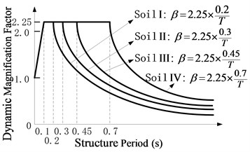
a) Elastic response spectrum for the soil profile I, II, III, and IV in Chinese criteria (JTJ 004-89)
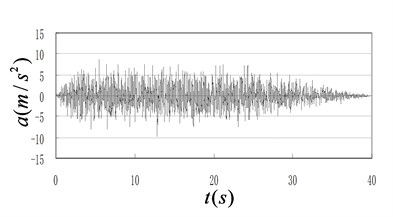
b) A representative accelerogram corresponding to the elastic response spectrum of the soil profile I
4.2. Ground motion
For each elastic response spectrum of the soil profile I, II, III, and IV in Chinese criteria (JTJ 004-89) as shown in Figure 3(a) [17], one accelerogram is generated by Simqke procedure to be the ground motion of the computer program [18]. One representative accelerogram out of four is shown in Figure 3(b). Other accelerograms are not presented due to the similarity to Figure 3(b).
4.3. Numerical simulations
A total of 90 cases are obtained by combining 6 damping constants and 15 rolling friction coefficients. As for each case, 4 accelerograms are input as the ground motion, whose peak ground accelerations (PGA) are adjusted to be 0.2, 0.4, 0.6 and 0.8 g, respectively. Thus, 1440 cases are generated, and each case is calculated by the computer program.
As for the case of the damping constant of 0 kN·s/m, it is the pure-rolling isolation system, and Wei Biao has investigated a calculation method of the isolation system by the theory analysis and a shake table test [14]. Based on the calculation method of the pure-rolling isolation system, this paper adds the calculation of a damper to obtain the computer program in Figure 2 by the theory of structural dynamics.
The results of the computer program are the accelerations, relative displacements and residual displacements of the structures. The structural acceleration directly indicates whether the earthquake destroys the structure. The relative displacement indicates if the structure leaves from its foundation, and if the structure collides with other things. The residual displacement relates to the post-earthquake restoration. Therefore, the following sections discuss those results, but only classical and common results are discussed in detailed manner due to space limitations while other results are considered but not listed.
5. Numerical results and discussions
5.1. Structural accelerations
Figure 4 represents the influence of the rolling friction coefficient on the maximum acceleration of the structure. The accelerogram of the soil profile I is input as the ground motion. The damping constant adopts 100 kN·s/m and 200 kN·s/m, respectively. The rules are shown as follows:
(1) The structural acceleration becomes larger as the rolling friction coefficient increases.
(2) By comparing Figures 4(a) and (b), the structural acceleration increases as the damping constant increases.
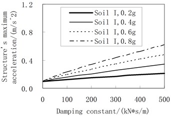
Figure 5 represents the influence of the damping constant on the maximum acceleration of the structure. The accelerogram of the soil profile I is input as the ground motion. The rolling friction coefficient adopts 0.01. The rules are shown as follows:
(1) The structural acceleration becomes larger as the damping constant increases.
(2) As for decreasing the structural acceleration, the less the damping constant the better. When the damping constant adopts 0, the maximum acceleration of the structure remains a constant of , where is the rolling friction coefficient.
As the structure is simplified as a rigid body, its maximum acceleration happens along with the maximum force applied to the structure, which contains the damping force which is a variable to the relative velocity of the structure, and the friction force which is a constant. The severer the earthquake is, the larger the relative velocity of the structure should be, and the larger the damping force should be. However, the rolling friction force always maintains a constant of . Therefore, the maximum accelerations of the structure in Figures 4 and 5 are obtained by adding a damping-induced acceleration to induced by the rolling friction force.
According to the theory of structural dynamics, when the period of a structure is close to the predominant period of an earthquake, increasing the damping ratio decreases the structural acceleration. However, when the period of a structure is much larger than the predominant period of an earthquake, increasing the damping ratio increases the structural acceleration. When the rolling-damper isolation system is concerned, it doesn’t have a determined period, i.e. its period is much larger than the predominant period of the earthquake. Therefore, increasing the damping ratio of the isolation layer increases the structural acceleration, i.e. Figure 5 is reasonable.
Fig. 4Influence of the rolling friction coefficient on the maximum acceleration
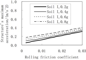
a) The damping constant is 100 kN·s/m
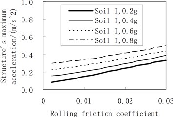
b) The damping constant is 200 kN·s/m
Fig. 5Influence of the damping constant on the maximum acceleration (the rolling friction coefficient is 0.01)
5.2. Relative displacements of the structure
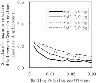
Figure 6 represents the influence of the rolling friction coefficient on the maximum relative displacement of the structure. The accelerogram of the soil profile I is input as the ground motion. The damping constant adopts 100 kN·s/m and 200 kN·s/m, respectively. In Figure 6, axis indicates the ratio between the structure’s maximum relative displacement and the ground’s maximum absolute displacement. In this way, all calculation results can be clearly drawn in one figure, and the influence of the rolling friction coefficient can be better expressed.
Based on Figure 6, rules are stipulated in the following:
(1) As a whole, the maximum relative displacement of the structure decreases as the rolling friction coefficient increases. Moreover, when PGA is little and the rolling friction coefficient is large, there are some fluctuations for the maximum relative displacement of the structure as the rolling friction coefficient increases.
(2) By comparing Figures 6(a) and (b), when the damping constant increases, the maximum relative displacement of the structure increases.
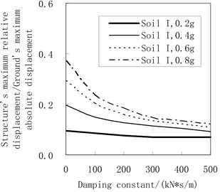
Figure 7 represents the influence of the damping constant on the maximum relative displacement of the structure. The accelerogram of the soil profile I is input as the ground motion. The rolling friction coefficient adopts 0.01. The rules are shown as follows:
(1) As a whole, the maximum relative displacement of the structure decreases as the damping constant increases. Moreover, the maximum relative displacement of the structure decreases faster when PGA is larger.
(2) The larger the damping constant is, the less the influence of PGA on the ratio between the structure’s maximum relative displacement and the ground’s maximum absolute displacement is.
In order to explain the rules above, the generation mechanism of the maximum relative displacement of the pure-rolling isolation system is analyzed firstly, and is divided into 3 stages:
Stage (1): when PGA is very little, the structure, subjected to the inertia force induced by the ground motion, doesn’t move relative to the ground since the inertia force is less than the friction force. Therefore, the isolation system doesn’t have the relative displacement.
Stage (2): when PGA is large, the structure, subjected to the inertia force induced by the ground motion, moves relative to the ground since the inertia force is larger than the friction force. Under the action of the friction force, the isolation structure has an acceleration and moves around. If the duration time of the earthquake isn’t very long, the relative velocity and the relative displacement of the isolation system are not very large.
Stage (3): when PGA becomes very large, the structure, subjected to the inertia force induced by the ground motion, significantly moves relative to the ground since the inertia force is much larger than the friction force. Under the weak action of the friction force, the acceleration of the isolation system is much less than PGA. Therefore, the relative velocity and the relative displacement of the isolation system become very large in a short time.
Fig. 6Influence of the rolling friction coefficient on the maximum relative displacement
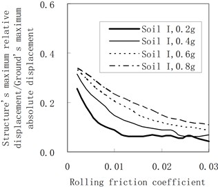
a) The damping constant is 100 kN·s/m
b) The damping constant is 200 kN·s/m
Fig. 7Influence of the damping constant on the maximum relative displacement (the rolling friction coefficient = 0.01)
Therefore, when a certain PGA is concerned, the movement of the pure-rolling isolation system can be changed from the stage (3) into the stage (2), and even into the stage (1) by increasing the rolling friction coefficient. And thus, the maximum relative displacement of the structure decreases as the rolling friction coefficient increases.
After adding the damper on the pure-rolling isolation system, the following effects are obtained:
(1) For the stage (3), the relative displacement is decreased obviously by the damper since the large relative velocity makes the great damping force.
(2) For the stage (2), the relative displacement is also decreased by the damper. However, the decreasing trend is not obvious since the little relative velocity only makes the small damping force.
(3) When the stage (1) is concerned, the damper doesn’t work as there is not any relative velocity.
In summary, the maximum relative displacement of the rolling-damper isolation system is decreased by increasing the damping constant. When PGA is large and the damping constant is little, the decreasing trend is obvious. As the results of other soil profiles obtain the similar rules, they are not presented here due to space limitations.
5.3. Residual displacement of the structure
Figure 8 represents the influence of the rolling friction coefficient on the residual displacement of the structure. The accelerogram of the soil profile I is input as the ground motion. The damping constant adopts 100 kN·s/m and 200 kN·s/m, respectively. The rules are as follows:
(1) As the rolling friction coefficient increases, there is no definite trend or even very disorder for the residual displacement.
(2) By comparing Figures 8(a) and (b), as the damping constant increases, there is no definite trend for the envelope value of the residual displacement.
Because the damper and the rolling ball can’t offer the restoring force, they can’t effectively decrease the residual displacement.
Fig. 8Influence of the rolling friction coefficient on the residual displacement
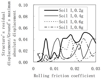
a) The damping constant is 100 kN·s/m
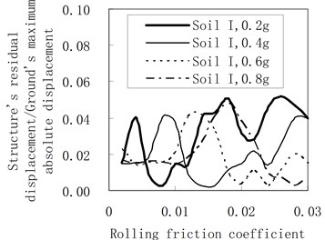
b) The damping constant is 200 kN·s/m
6. Conclusions
In this paper, a computer program is compiled, which is then used to analyze the influence of rolling friction coefficients, damping constants and other factors on the seismic performance of a rolling-damper isolation system. The conclusions are summarized as following:
(1) Generally, increasing the rolling friction coefficient and the damping constant decreases the relative displacement of the structure. However, it increases the structural acceleration, and has no obvious influence on the residual displacement of the structure.
(2) Under a certain range of design earthquakes, an appropriate combination of the damping constant and the rolling friction coefficient, efficiently decreases the relative displacement, and keeps the structural acceleration around the theoretical minimum value.
For different bridges and buildings subjected to different earthquakes, it is better to give a formulation to choose the appropriate combination of the damping constant and the rolling friction coefficient, which can make the isolation systems achieve the best seismic response. And it needs further investigation.
References
-
Shakeri K., Tarbali K., Mohebbi M. An adaptive modal pushover procedure for asymmetric-plan buildings. Engineering Structures, Vol. 36, Issue 1, 2012, p. 160-172.
-
Paraskeva T. S., Kappos A. J. Further development of a multimodal pushover analysis procedure for seismic assessment of bridges. Earthquake Engineering and Structure Dynamics, Vol. 39, Issue 3, 2010, p. 211-222.
-
Pelo L., Aprile A., Benedetti A. Comparison of seismic assessment procedures for masonry arch bridges. Construction and Building Materials, Vol. 38, Issue 1, 2013, p. 381-394.
-
Camara A., Astiz M. A. Pushover analysis for the seismic response prediction of cable-stayed bridges under multi-directional excitation. Engineering Structures, Vol. 41, Issue 2, 2012, p. 444-455.
-
Wei Biao Seismic Design Theory of Typical Irregular Continuous Bridges. Thesis, Tongji University, Shanghai, 2010, (in Chinese).
-
Jangid R. S., Londhe Y. B. Effectiveness of elliptical rolling rods for base isolation. Journal of Structural Engineering, Vol. 124, Issue 4, 1998, p. 469-472.
-
Jangid R. S. Stochastic seismic response of structures isolated by rolling rods. Engineering Structures, Vol. 22, Issue 8, 2000, p. 937-946.
-
Ou Y. C., Song J. W., Lee G. C. A parametric study of seismic behavior of roller seismic isolation bearings for highway bridges. Earthquake Engineering and Structure Dynamics, Vol. 39, Issue 5, 2010, p. 541-559.
-
Lee G. C., Ou Y. C., Niu T. C., Song J. W., Liang Z. Characterization of a roller seismic isolation bearing with supplemental energy dissipation for highway bridges. Journal of Structural Engineering, Vol. 136, Issue 5, 2010, p. 502-510.
-
Guerreiro L., Azevedo J., Muhr A. H. Seismic tests and numerical modeling of a rolling-ball isolation system. Journal of Earthquake Engineering, Vol. 11, Issue 1, 2007, p. 49-66.
-
Kurita K., Aoki S., Nakanishi Y., Tominaga K., Kanazawa M. Fundamental characteristics of reduction system for seismic response using friction force. Journal of Civil Engineering and Architecture, Vol. 5, Issue 11, 2011, p. 1042-1047.
-
Monfared H., Shirvani A., Nwaubani S. An investigation into the seismic base isolation from practical perspective. International Journal of Civil and Structural Engineering, Vol. 3, Issue 3, 2012, p. 451-463.
-
Nanda R. P., Agarwal P., Shrikhande M. Base isolation system suitable for masonry buildings. Asian Journal of Civil Engineering (Building and Housing), Vol. 13, Issue 2, 2012, p. 195-202.
-
Wei Biao, Dai Gong-Lian, Yu Xiang-Dong, Zeng Qing-Yuan, Wang Jun-Wen Comparison study of calculation methods of seismic displacement for the isolation system based on pure rolling. Journal of Civil, Architectural and Environmental Engineering, Vol. 34, Issue 5, 2012, p. 116-120, (in Chinese).
-
Wei Biao, Li Shan-Shan Study on a roller-footing isolated single-pier system. Applied Mechanics and Materials, Vol. 204-208, 2012, p. 2658-2661.
-
Xia Y., Ma H. Y., Su D. Strain mode based damage assessment for plate like structures. Journal of Vibroengineering, Vol. 15, Issue 1, 2013, p. 55-63.
-
Standard of the Ministry of Communications of P. R. China. JTJ004-89 Specifications of Earthquake Resistant Design for Highway Engineering. China Communications Press, Beijing, 1989, (in Chinese).
-
Fahjan Y., Ozdemir Z. Scaling of earthquake accelerograms for non-linear dynamic analysis to match the earthquake design spectra. The 14th World Conference on Earthquake Engineering, Chinese Society for Earthquake Engineering, 2008.
About this article
This paper is supported by the China Postdoctoral Science Foundation Grant No. 2011M500983 and Postdoctoral Science Foundation of Central South University and Freedom Explore Program of Central South University Grant No. 2012QNZT047 and Nation Natural Science Foundation of China Grant No. 51308549.
