Abstract
This paper addresses the issues of damage assessment for plate-like structures using strain mode technique. Based on the relationships between displacement mode and strain mode of a vibrating structure, this paper presents a derivation to show the relationship between the changes of strain mode shape and structural damage firstly. Herein, damages in terms of small holes are assumed to be the reduction of structural stiffness in according areas. Structural damage can thus be located and quantified using the proposed damage assessment index based on strain mode change. A numerical study on a cantilever plate is conducted to verify the accuracy and sensitivity of strain mode shapes for damage assessment. The following conclusions can be made: (i) the strain mode is more sensitive than the displacement mode to structural damage; (ii) the change of the strain mode can be used to locate both single and multiple point damage; and (iii) the damage severity can also be quantified through the magnitude of the strain mode shape change. Moreover, the results also show that in condition of limited or sparse measurements, the workability of strain mode shape for damage assessment is quite applausive.
1. Introduction
The detection of structural damage at its early developing stage and identifying their location and severity is one of the recent research focuses in mechanical, aeronautic and civil engineering community [1-3]. Different classes of methodologies were proposed for this purpose [4-9]. Among them, the vibration based damage assessment technique attracts the most research interests [8-10]. Generally, vibration based damage assessment techniques rely on structural modal parameters estimated using structural acceleration measurement to detect, locate, and quantify damage. Since the strain responses of structural components can more easily be measured, it is quite reasonable to develop structural damage assessment techniques based on strain measurement [11-13].
Various methods for damage identification using modified modal properties have been proposed, e.g. natural frequencies and mode shapes [14]. Studies on modal strain analysis and the establishment of strain transfer function have been carried out [8, 11, 14]. A review of detecting damage from changes in natural frequencies is presented, allowing a general prediction of the global damage [3]. In order to determine the location of the damage, additional information from mode shapes is required. Absolute changes in mode shape curvature are demonstrated to be a good indicator of damage using a beam structure example due to their local sensitivity [15]. A method is presented by Cornwell et al. based on the decrease in modal strain energy between two structural degrees of freedom as defined by the curvature of the measured mode shapes [16].
However, the methodologies available based on modal strain are either complicated for application or not intuitive enough to understand. It is highly desirable to develop an accessible and feasible damage index for structural damage assessment. Strain mode shape is the first order differential of displacement mode shape. According to some previous studies on 2-dimension beams or frame structures, strain mode shape is a sensitive parameter to damage [17]. When it is used to identify damage in complex structural systems, such as the 3-dimension plate like structures, the workability of this technique need to be further verified.
In this paper, a derivation to show the relationship between the changes of strain mode shape and structural damage is presented firstly based on the relationships between displacement mode shapes and strain mode shapes of a structure. Herein, structural damage is assumed to be the reduction of structural stiffness. A numerical study on a cantilever plate is then conducted to verify the accuracy and sensitivity of strain mode shapes for damage assessment. In the numerical study, the sensitivity of strain mode and the displacement mode to structural damage are compared firstly. After that, a study simulating the coarse sensor placement is conducted to verify the feasibility of the strain mode based damage assessment technique. Finally, both single point damage and multiple point damage cases with different levels of stiffness reduction are simulated to check the capacity of stain mode on structural damage localization and quantification.
2. Formulations
2.1. Dynamic equation and modal analysis
The equation of motion for a finite element model can be written as:
where , and are the mass, damping and stiffness matrixes, respectively, is the external excitation, and , and are the acceleration, velocity and displacement responses of structures.
Under the assumption of proportional damping, this physical system can be transferred into modal domain and its solution can be expressed as:
where is the displacement modal matrix satisfying:
in which, and are natural frequency and damping ratio of th vibration mode, respectively. is the modal coordinate response, and its th component is governed by:
where is the th mode shape vector.
2.2. Derivation of modal strain
Notice the following relationship between strains and displacements:
where and are displacements along x and y axes respectively. The transformation equation of strain mode shapes from displacement mode shapes can be expressed as [7]:
where is the transfer matrix in dependence on the discrete finite element model and the adoptive difference scheme, and presents the strain mode shape matrix.
2.3. Increment of modal strain
A damage occurring in the structure may leads to a variation of structural dynamic parameters as stiffness matrix, natural frequency, modal strain, modal displacement, modal curvature, etc. Suppose stiffness matrix, square of natural frequency and modal displacement matrix of the damaged structure are , and , respectively. Then the incremental forms of stiffness matrix, square of natural frequency and modal displacement matrix can be written as:
The above dynamic parameters must satisfy the eigenvalues equations as follows:
Substituting equation (4) into (5) yields:
which, by neglecting the higher order terms, leads to:
Thus:
In terms of the invariance of transfer matrix B in equation (6) with structural damage, the incremental form of modal strain can be derived as:
If the changes of structural frequency can be further neglected, the increment of strain mode shapes caused only by is:
Therefore is the only variable at the right-hand side, which means that and is of a linear relationship approximately when is small. Moreover, when increases, will be more and more sensitive to , or say damages.
3. Modal analysis
Generally, damages in form of a loss of local stiffness in a structure would more or less alter the system physical properties as vibration parameters of the structure, i.e., the modal frequencies, mode shapes and modal damping values. It means a possibility exists for damage detection and localization using the variations in the vibration parameters as indicators. For a modal parameter based damage detection index, however, its sensitivity to damage may be a crux.
Aiming at verification of the sensitivity of modal strain technique, a thin cantilever plate with and without damages is to be adopted here. The background of this example is related to engineering applications in construction of bridges, buildings, ships, etc., since the thin plate components in these structures may have rust holes or crash pit damages. Therefore, the study of such a plate with these type damages is of general significance.
3.1. A quadrate thin cantilever plate
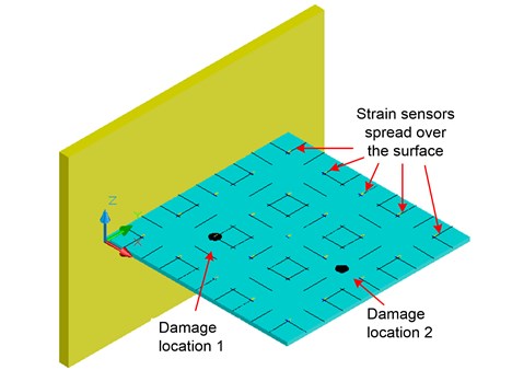
A numerical study on a steel quadrate thin cantilever plate with one edge fixed and the other three edges free, as shown in Fig. 1, is conducted to verify the strain mode based technique. The cantilever plate dimensions 1000 mm×1000 mm×10 mm. The materials properties are set as 19.5×10¹⁰·N/m2, 7850 kg/m3, 0.3. Uniaxil strain gagues are spread over the top surface of the plate along and axis with spacing of 200 mm, also shown in Fig. 1.
As mentioned previously, damage patterns, e.g., rust holes, severe scratches, and crash pit damages, may exist in thin plate components of bridges, buildings, ships, etc., where the damages shall be emulated as physical stiffness loss in the damage vicinity. In the numerical study, stiffness reduction is placed as damage to a circular area with the radius of in locations shown in Fig. 1. Different levels of damages are simulated by reducing the stiffness of this area for 10 %, 20 %, 30 %, 50 %, and 80 %, respectively. Both single and double damage cases are simulated. The black dots represent these two holes at damage location 1 and 2. Simulations are conducted through a commercial FEM program ANSYS 10.0 [18].
Fig. 1A quadrate thin cantilever plate (1000×1000×10 mm, E= 19.5×10¹⁰ N/m2, ρ= 7850 kg/m3, μ= 0.3)
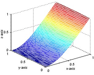
Structural displacement and strain mode shape are obtained through the eigenvalues analysis. Table 1 shows the natural frequencies of the first five modes. The first displacement mode shapes with and without the single-hole damage, are shown in Fig. 2(a) and (b). In the same manner, the -direction strain mode shapes with and without the single-hole damage are shown in Fig. 3(a) and (b).
Table 1The first five order natural frequencies
f1(Hz) | f2(Hz) | f3(Hz) | f4(Hz) | f5(Hz) | |
Intact structure | 8.3635 | 20.521 | 51.246 | 65.830 | 74.708 |
Damaged structure | 8.3289 | 20.419 | 51.122 | 65.074 | 74.293 |
Change ratio | 0.41 % | 0.50 % | 0.24 % | 1.15 % | 0.56 % |
3.2. Modal analysis of intact and damaged plate
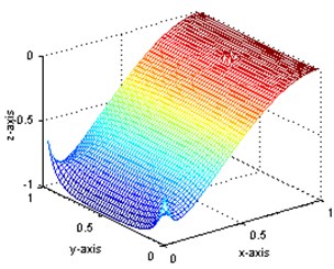
For demonstrating the applicability of present method, simulated data will be used instead of measured data. Thus a great many of measurement points can be implemented using finite element method to get more sufficient strain values and displacement values. These points are placed every 20 mm over the surface of the plate, so there are 49×49 internal measurement points. The first displacement mode shapes of intact state and damaged state are obtained and shown in Fig. 2(a) and (b) while the first strain mode shape in Fig. 3(a) and (b), respectively. In these figures, the and axes indicate the position on the plate, and the Z-axis presents the relative mode shape value. All the mode shapes have been normalized to a uniform scale. As shown, the first mode is a bending mode. The first five order frequencies for intact and damaged structures as well as their damage ratios are also shown in Table 1. As shown, the frequency change ratios are less than 2 %.
Through the comparison of Fig. 2(a) and (b), it is indicated that the displacement mode is insensitive to this type of damage: no obvious abnormality can be observed even at the circumferences of the holes. However, for the strain mode, obvious diversity can be seen between Fig. 3(a) and (b) in the damage position, although they are of quite similar shape. In order to verify the capability of modal parameters for damage identification, further research is to be carried out.
Fig. 2The first order displacement mode shape
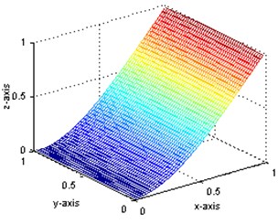
a) The displacement mode shape of intact plate
b) The displacement mode shape of damaged plate
Fig. 3The first order strain mode shape
a) The strain mode shape of intact plate
b) The strain mode shape of damaged plate
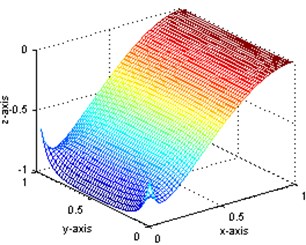
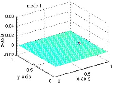
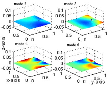
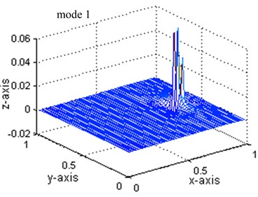
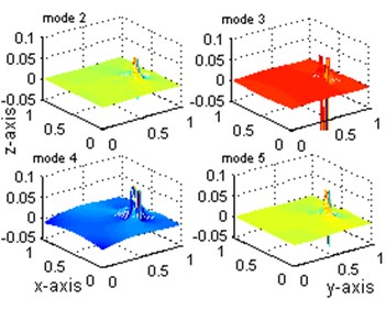
Define the differences of the mode shapes before and after damage as the damage index, similar conclusion can be drawn in the similar manner. Fig. 4 shows the change of the first five displacement modes and Fig. 5 shows the change of the first five strain modes.
As shown in Fig. 4, although the change of the first three displacement mode can clearly locate the damage position, the changes of the 4th and 5th displacement mode are so confused for damage localization and the index peaks value is quite small which is hard to detect. Contrastively, the changes of the all five stain modes shown in Fig. 5 have the largest value at the damaged points and a smaller value at the adjacent-to-damage element. The value is very small at points far away from the damaged points. This observation is consistent with the previous observation from Figs. 2 and 3: the index defined from the strain mode shape can give stronger indication of damage location than that from the displacement mode change. The peak values, 0.0042 shown in Fig. 4 and 0.063 shown in Fig. 5 for mode 1, also provide strong evidence for the sensitivity of strain mode shape.
Fig. 4Comparisons of displacement mode shapes: mode 1 to 5
a)
b)
Fig. 5Comparisons of strain mode shapes: mode 1 to 5
a)
b)
4. Damage assessment
4.1. Damage localization at single and multiple point
For practical applications, obtaining adequate and accurate enough information from only a small quantity of measurement points is a key problem for damage identification methods. In this study to determine a reasonable and effective schematic for placement of measurement points, only 3×3 measurement points are settled in the plate tentatively. Theoretically, the values on the edge of the plate are always around zeros, so it is meaningless to set measurement points at edges. Whether it can afford the damage identification effectively determines the feasibility of this method. Only the first order strain mode shape is discussed below.
Under this sensor placement, the following three damage case scenarios are assumed:
I) The damage occurs only in location 1 (see Fig. 1) with the stiffness decreased by 10 % to 80 %;
II) The damage occurs only in location 2 with the stiffness decreased by 10 % to 80 %;
III) The damages occur in location 1 and location 2 with the same damage degree from 10 % to 80 %.
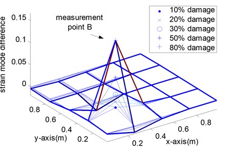
Fig. 6Indices of various damage scenarios from sparse measurement points
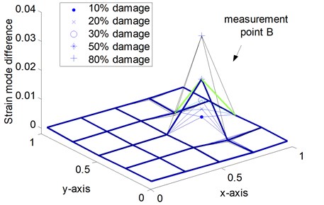
a) Case I: single point damage at location 1
b) Case I: single point damage at location 1
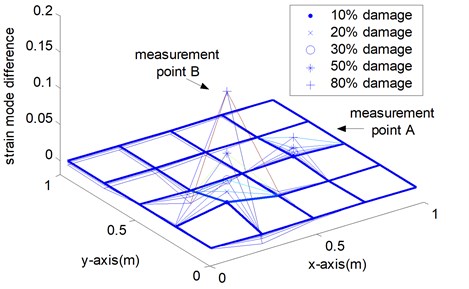
c) Case III: multiple point damage at location 1 and 2
Figure 6 shows the measured strain mode changes in accordance with the three damage cases, which exhibit the following properties. Firstly, the maximum of the index appears at the point around the defective area. However, in the other measurement points, the value changes little. No matter which mode is selected for the analysis, the damage location can always be identified correctly in the numerical simulation. Secondly, when the damage position changes, this damage localization method still works. The damage location can be fixed in the range near the peak point. Thirdly, in Fig. 6 (c), the index values at two damage positions are the sum of the values of measurement point 1 and measurement point 2 respectively. Taking notice of equation (3) and Table 1, when is small, multiple damage with different location rarely affect each other and could be detected respectively. Thus, the strain mode change could be a meaningful indicator for damage localization.
4.2. Damage quantification
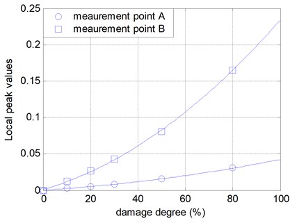
The index peak values of case III are shown in Fig. 7. As the damage grows from 0 % to 80 %, the peak values increase accordingly. As shown in this figure, when is small, the strain mode change can be regarded as the linearly increased along with the increase of the stiffness changes. The nonlinearity observed when the damage degree is beyond 50 percent is due to that when the damage is severe the change of stiffness matrix can not be neglected. In this point, it can be used as a measure of damage extent.
Fig. 7Local peak values of strain mode shape difference
5. Conclusions
In this paper, a derivation to show the relationship between the changes of strain mode shape and structural damage is presented firstly based on the relationships between displacement mode shapes and strain mode shapes of a structure. Herein, structural damage is assumed to be the reduction of structural stiffness. A numerical study on a cantilever plate is then conducted to verify the accuracy and sensitivity of strain mode shapes for damage assessment.
Based on the theoretical and numerical study, the following conclusions can be drawn: the strain mode is more sensitive than the displacement mode to structural damage; the change of the strain mode can be used to locate both single point damage and multiple point damage; by checking the magnitude of the strain mode shape change, the damage severity can also be quantified. Moreover, the results also show that in condition of coarse sensor installation the requirement of coarse sensor placement can be satisfied with little influence on the workability of strain mode shape for damage assessment.
References
-
Doebling S. W., Farrar C. R., Prime M. B., Shevitz S. W. Damage Identification and Health Monitoring of Structural and Mechanical Systems from Changes in their Vibration Characteristics: a Literature Review. Los Alamos National Laboratory Report LA-13070-VA5, 1996.
-
Zou Y., Tong L., Steven G. P. Vibration-based model dependent damage (delamination) identification and health monitoring for composite structures – a review. Journal of Sound and Vibration, Vol. 230, Issue 2, 2000, p. 357-378.
-
Salawu O. Detection of structural damage through changes in frequency: a review. Engineering Structures, Vol. 19, Issue 9, 1997, p. 718-723.
-
Alvandi A., Cremona C. Assessment of vibration-based damage identification techniques. Journal of Sound and Vibration, Vol. 292, Issue 1-2, 2006, p. 179-202.
-
Adewuyi A. P., Wu Z. S., Serker N. H. M. K. Assessment of vibration-based damage identification methods using displacement and distributed strain measurements. Structural Health Monitoring, Vol. 8, Issue 6, 2009, p. 443-461.
-
Mustapha F., Aris K. D. M., Wardi N. A., Sultan M. T. H., Shahrjerdi A. Structural health monitoring for composite structure undergoing tensile and thermal testing. Journal of Vibroengineering, Vol. 14, Issue 3, 2012, p. 1342-1353.
-
Yam L. H., Leung T. P., Li D. B., Xue K. Z. Theoretical and experimental study of modal strain analysis. Journal of Sound and Vibration, Vol. 191, Issue 2, 1996, p. 251-260.
-
Dems K., Mroz Z. Identification of damage in beam and plate structures using parameter-dependent frequency changes. Engineering Computations, Vol. 18, Issue 1, 2001, p. 96-120.
-
Shi Z. Y., Law S. S. Structural damage localization from modal strain energy change. Journal of Sound and Vibration, Vol. 218, Issue 5, 1998, p. 825-844.
-
Chen H. P., Bicanic N. Assessment of damage in continuum structures based on incomplete modal information. Computers & Structures, Vol. 74, Issue 5, 2000, p. 559-570.
-
Unger J. F., Teughels A., De Roeck G. Damage detection of a prestressed concrete beam using modal strains. Journal of Structural Engineering ASCE, Vol. 131, Issue 9, 2005, p. 1456-1463.
-
Yam L. H., Li Y. Y., Wong W. O. Sensitivity studies of parameters for damage detection of plate-like structures using static and dynamic approaches. Engineering Structures, Vol. 24, Issue 11, 2002, p. 1465-1475.
-
Ahmadian H., Mottershead J. E., Friswell M. I. Damage location indicators from substructure mode shapes. Inverse Problems in Engineering, Vol. 8, Issue 4, 2000, p. 309-323.
-
Oliveira S., Toader A. M., Vieira P. Damage identification in a concrete dam by fitting measured modal parameters. Nonlinear Analysis: Real World Applications, Vol. 13, Issue 6, 2012, p. 2888-2899.
-
Pandey A. K., Biswas M., Samman M. M. Damage detection from changes in curvature mode shapes. Journal of Sound and Vibration, Vol. 145, Issue 2, 1991, p. 321-332.
-
Cornwell P., Doebling S. W., Farrar C. R. Application of the strain energy damage detection method to plate-like structures. Journal of Sound and Vibration, Vol. 224, Issue 2, 1999, p. 359-374.
-
Zhang Z., Aktan H. M. The damage indices for the constructed facilities. SPIE Proceedings of the 13th International Modal Analysis Conference, Vol. 2460, 1995, p. 1520.
-
ANSYS® Academic Research. Release 10.0, ANSYS Inc., 2007.
About this article
