Abstract
With the increase in the use of adhesively bonding in primary structures, reliable and cost-effective techniques for structural health monitoring of adhesive bonding are needed. Vibration-based tests, when combined with validated FEA, can provide a key tool for structural health monitoring of adhesive bonding. This paper deals with forced vibration behavior of adhesively bonded single-lap joint theoretically and experimentally. The finite element analysis (FEA) software was used to predict the natural frequencies, mode shapes and frequency response functions (FRFs) of the joint. The dynamic test software and the data acquisition hardware were used in experimental measurement of the dynamic response of the joint. The predicted results were compared with experimentally measured ones to validate the prediction technique. It was found that the forced vibration behavior predicted from FEA matches reasonably well with the experimental observations. It can be concluded that the FEA of the forced vibration behavior of adhesively bonded single-lap joint will help future applications of adhesive bonding by allowing different parameters to be selected to give as large a process window as possible for adhesively bonded joints vibration analysis.
1. Introduction
The need to design lightweight structures and the increased use of lightweight materials in industrial fields, have led to wide use of adhesive joints in recent years. Consequently, the mechanical behavior of these joints has been the subject of a considerable amount of experimental and numerical studies [1-4]. In the design of mechanical structures, which consist of jointed components, for minimum vibration response, a specific knowledge of the damping capacity of the component materials and joints is important. Saito and Tani [5] have investigated the natural frequencies and loss factors of coupled longitudinal and flexural vibrations. Miles and Reinhall [6] have presented a comprehensive model for the vibration of a sandwich beam by including the effects of both shear and thickness deformation in the adhesive layer. He and Rao [7, 8] established an analytical model to study the coupled transverse and longitudinal vibration of a bonded lap-joint system consisting of a pair of parallel and identical beams which are lap-jointed over a certain length by a viscoelastic material. Ko et al. [9], and Lin et al. [10] have used the finite element analysis (FEA) to predict the free vibration behavior of bonded plates. In an early research, the present author and co-worker [11, 12] investigated in detail the influence of the characteristics of structural adhesives on the free transverse and torsional vibration of single-lap cantilevered bonded beams and found that the natural frequencies of the beams increase with increasing adhesive Young’s modulus whereas any significant change was not observed with increasing Poisson’s ratio.
The focus of this paper is on numerical and experimental investigations of the forced vibration behavior of adhesively bonded single-lap joint. The ABAQUS FEA software was used to predict the natural frequencies, mode shapes and frequency response functions (FRFs) of the joint. The LMS (Leuven Measurement System) CADA-X dynamic test software and the LMS-DIFA Scadas II 48 channel data acquisition hardware were used in experimental measurement of the dynamic response of the joint. The FRFs predicted using FEA were compared with those measured experimentally to validate the feasibility of the FEA method.
2. Configuration and properties of adhesively bonded Single-Lap joint
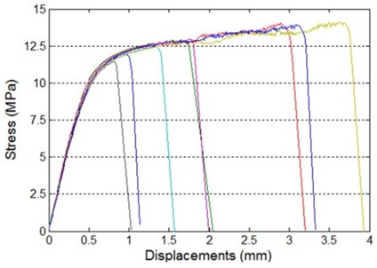
The adhesively bonded single-lap joint studied in the present work is shown in Fig. 1. The two adherends used were aluminum alloy plates of dimensions 200 mm long × 25 mm wide × 4 mm thickness. The mechanical properties of the aluminum alloy plates were as follows: Young’s modulus, 70 GPa; Poisson’s ratio, 0.33. As the fatigue loading is a common cause of failure in adhesively bonded joints, the durability is then one of the most important issues. For adhesives, the presence of the fatigue loading is found to lead to a much lower resistance to crack growth than under monotonic loading. In other words, adhesives should have both high static strength and good fatigue properties change in time under the load. The adhesive used in the present study was two components acryloid cement. The mechanical properties of the adhesive investigated were: Young’s modulus 2 GPa and Poisson’s ratio 0.30 which had been proved as an excellent adhesive property [13]. The specimens were bonded under constant pressure by using clips and cured for at least 24 hours at room temperature. Fig. 2 and Fig. 3 show the tensile-shear and fatigue properties of the adhesively bonded single-lap joint.
Fig. 1An adhesively bonded single-lap joint
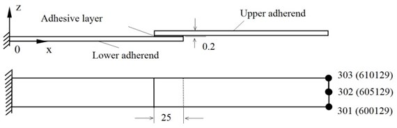
Fig. 2Tensile-shear properties of adhesively bonded single-lap joint
3. Finite element modelling
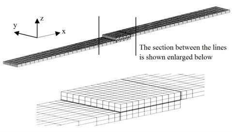
In the case of the FEA of adhesively bonded single-lap joint, the FEA mesh must accommodate both the small dimension of the adhesive layer and the larger dimension of the adherends. Fig. 4 shows the original FEA mesh of adhesively bonded single-lap joint. The FEA mesh of the joint was created using the ABAQUS FEA pre-processing program. Most of the adherends and adhesive were modeled using the 20-node solid elements. At the transition zones from the adherends to the adhesive, some 15-node transition elements were used. In this case, the transition elements were used in both the lap-jointed section of the adherends as well as the section of the adherends which were outside the lap-jointed section. The adhesive layer was divided into 10 equal parts along its length (-direction) and 10 equal parts along its width (-direction). Nodal points were located by the ABAQUS input file as a function of the length and width of the adhesive layer. The location of these point was in accordance with the geometric parameters of the model. Also the material parameters of the adhesive and adherends were input via the ABAQUS input file.
Fig. 3Fatigue properties of adhesively bonded single-lap joint
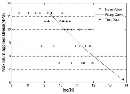
Fig. 4Original FEA mesh of the adhesively bonded single-lap joint
The FEA programs were run to predict both free and forced vibration response. For free vibration, the program predicted the first 50 frequencies and mode shapes. For forced vibration, a sinusoidal forcing function of magnitude 10 N with a frequency range of 0 to 1000 Hz was applied to the edge of the joint at a distance of 20 % of the length of the joint from the clamped edge. The frequency response functions (FRFs) at the tip locations of the adhesively bonded single-lap joint were predicted.
4. Test rig and data acquisition hardware
The LMS CADA-X software was used in conjunction with the LMS-DIFA Scadas II 48 channel data acquisition hardware for the following dynamic tests. The software has a high speed 12-bit or 16-bit analogue to digital converter (ADC), 48 channels with programmable dual filtering (PDF), and four channels of signal generation via a quadruple digital to analogue converter (QDAC) [14].
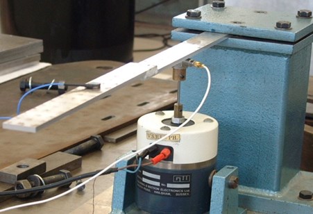
One end of the adhesively bonded single-lap joint was clamped in a heavy support. An electromagnetic exciter (shaker) was connected to the adhesively bonded single-lap joint, via a force transducer, at a location which was 20 % of the length of the joint from the clamped end and very close to a free edge as shown in Fig. 5 and Fig. 6. The shaker was excited by a band limited random signal which was produced digitally in a computer by the LMS CADA-X experimental modal analysis software [15].
Fig. 5Schematic diagram of the equipment used in the experimental test
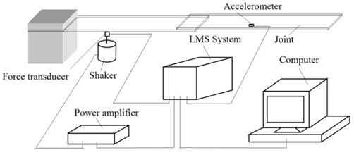
Fig. 6Experimental set up of the adhesively bonded single-lap joint
The digital signal was converted into an analogue signal by the data acquisition system, amplified by the power amplifier and applied to the shaker. An accelerometer was fixed to selected points on the joint and was used to measure the frequency response of the joint at these points. The output of the force transducer and accelerometer were connected to LMS system which amplified and transduced the force and acceleration signals into voltages. These voltage signals were sampled and digitised by the data acquisition system which transferred the measured data to the computer for processing using the LMS CADA-X modal analysis software.
5. Comparison of measured and predicted natural frequencies of the joint
The natural frequencies of the adhesively bonded single-lap joint predicted using the FEA and measured using the test rig are compared in this section. Fig. 7 shows the natural frequencies from FEA and from experimental measurement. It can be said that the figure shows good agreement between the measured and predicted natural frequencies of the joint as although 16 natural frequencies are extracted, the first few ones are important. It is also clear that the natural frequencies from experiment are lower than those predicted using FEA. This is because the support which clamps the joint is not infinitely rigid, there is an effect of the finite stiffness of the support on the measured modal characteristics. In the FEA, however, the joint was clamped with infinite rigidity. Therefore the experimental results may not compare very well with the FEA results obtained under the assumption of infinite support stiffness.
6. Comparison of measured and predicted modal shapes
Mode shapes are very important in the dynamic response analysis of adhesively bonding. If they are known at the design stage, the nodes can be placed in the proper region of the structures. In order to obtain accurate mode shapes, as many as possible measuring points should be set up. Consider the joint dimension and accelerometer size, the joint was divided into 30 equal parts along its length (x-direction) and 2 equal parts along its width (y-direction). This results total 93 measuring points as shown in Fig. 8.
Fig. 7Comparison of measured and predicted natural frequencies of the joint
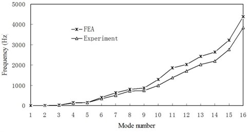
Fig. 8Measuring points of the joint
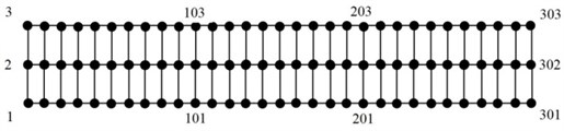
Fig. 9 shows the comparison of the first 4 transverse mode shapes from experiments and FEA for the adhesively bonded single-lap joint. It is seen that all corresponding mode shapes are similar. It can be seen from figures that the free edges of the experimental mode shapes are not smooth like those of the mode shapes predicted by FEA. This is because the dynamic response of joint depended on the force transducer locations in the system. Some complexity in the mode shapes can be attributed to force transducer mass contribution to the overall system mass.
7. Comparison of measured and predicted FRFs
The FRFs of the adhesively bonded single-lap joint were measured using the LMS CADA-X experimental modal analysis software and the LMS-DIFA Scadas II data acquisition hardware. The frequency range of the measurements was 0 Hz – 8000 Hz. The number spectral lines were set up as 16384, which corresponded to a resolution of 0.488 Hz, in order to obtain an accurate indication of the variation of the FRFs. As the first several vibration modes are more important, only frequency range 0 Hz – 500 Hz will be discussed in this section.
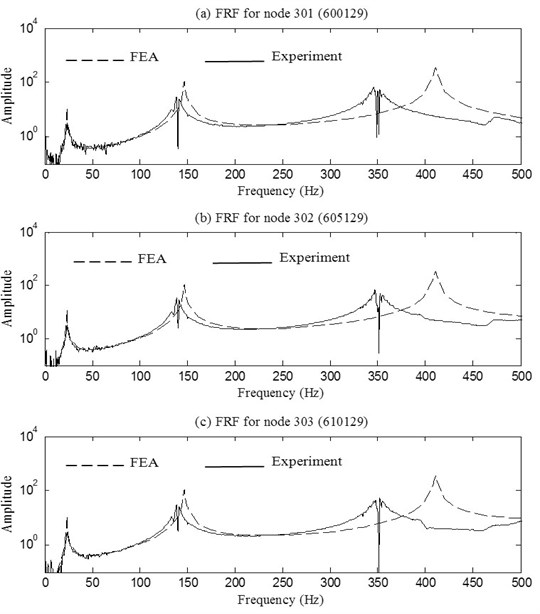
For comparison with the measured FRFs, the forced vibration steady-state FRFs of the joint were computed using FEA. The “Steady-State Dynamics” and “Modal Damping” options were used in the ABAQUS FEA in order to predit accurate FRFs. In the case of forced vibration of the adhesively bonded single-lap joint, the dynamical response of the free edge is most important because it fully represents the dynamical characteristic of the joint. Nodes 301, 302 and 303 in Fig. 1 are the nodes at the two corners and centre of the free edge of the joint (the corresponding nodes in the FEA mesh are 600129, 605129 and 610129 respectively).
The overlay of the FRFs predicted using FEA and measured experimentally at the two corners and centre of the free edge of the joint is shown in Fig. 10. In this figure, the dash line denotes the FRFs predicted using FEA and the solid line represents the FRFs measured experimentally. It can be seen from figure that the measued FRFs are close to the predicted FRFs for the first few modes of vibration of the joint. As mentioned above, for fully exciting the joint, the force transducer was connected to the location which was 20 % of the length of the joint from the clamped end and very close to a free edge. The accelerometer was connected to different locations (as shown in Fig. 8) of the joint for obtaining precise mode shapes. As a result some complexity appears in the FRFs graphics.
Fig. 9Comparison of the first 4 transverse mode shapes for the joint
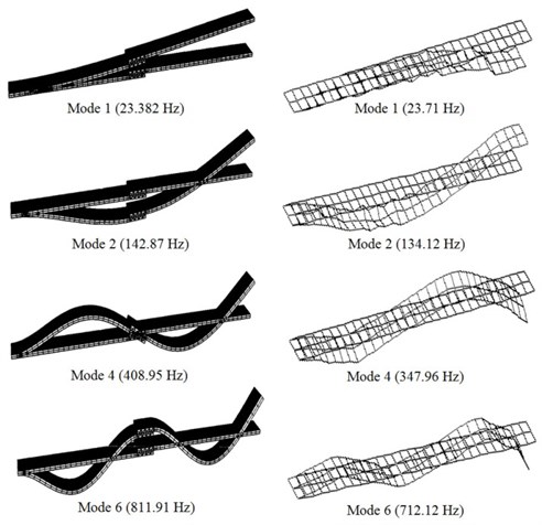
Fig. 10Comparison between FRFs predicted by FEA and measured experimentally for the joint
8. Conclusions
The forced vibration behavior of adhesively bonded single-lap joint has been investigated theoretically and experimentally. The ABAQUS finite element analysis (FEA) software was used to predict the natural frequencies, mode shapes and frequency response functions (FRFs) of the joint. The LMS system was used in experimental measurement of the dynamic response of the joint. The following conclusions can be drawn based on the results obtained from the present investigation:
The natural frequencies of the adhesively bonded single-lap joint from experiment are lower than those predicted using FEA. This is because the support which clamps the joint is not infinitely rigid, there is an effect of the finite stiffness of the support on the measured modal characteristics.
The measued FRFs are close to the predicted FRFs for the first few modes of vibration of the adhesively bonded single-lap joint. For the higher order modes of vibration, there is considerable discrepancy between the measured and predicted FRFs. This discrepancy can be attributed to locations and additional masses of force transducer and accelerometer.
References
-
He X. A review of finite element analysis of adhesively bonded joints. International Journal of Adhesion and Adhesives, Vol. 31, 2011, p. 248-264.
-
Adams R. D., Comyn J., Wake W. C. Structural Adhesive Joints in Engineering. London: Chapman and Hall, 1998.
-
He X., Ichikawa M. Effect of thickness control of adhesive layer on strength of adhesive joints. Proceedings of the 70th JSME Spring Annual Meeting, Tokyo, 1993, p. 166-168, (in Japanese).
-
He X. Static and Dynamic Analysis of Single Lap-Jointed Cantilevered Beams. Ph. D. Dissertation, University of Manchester, UK, 2003.
-
Saito H., Tani H. Vibration of bonded beams with a single lap adhesive joint. Journal of Sound and Vibration, Vol. 92, 1984, p. 299-309.
-
Miles R. N., Reinhall P. G. An analytical model for the vibration of laminated beam including the effects of both shear and thickness deformation in the adhesive layer. ASME Journal of Vibration, Acoustics, Stress and Reliability in Design, Vol. 108, 1986, p. 56-64.
-
He S., Rao M. D. Vibration analysis of adhesively bonded lap joint, Part 1: Theory. Journal of Sound and Vibration, Vol. 152, 1992, p. 405-416.
-
Rao M. D., He S. Vibration analysis of adhesively bonded lap joint, Part 2: Numerical solution. Journal of Sound and Vibration, Vol. 152, 1992, p. 417-425.
-
Ko T. C., Lin C. C., Chu R. C. Vibration of bonded laminated lap-joint plates using adhesive interface elements. Journal of Sound and Vibration, Vol. 184, 1995, p. 567-583.
-
Lin C. C., Ko C. T. Free vibration of bonded plates. Computers & Structures, Vol. 64, 1997, p. 441-452.
-
He X., Oyadiji S. O. Three dimensional FEA of torsional free vibration of bonded beams. Proceedings of International Conference DYMAC’99, Manchester, UK, 1999, p. 481-487.
-
He X., Oyadiji S. O. Influence of adhesive characteristics on the transverse free vibration of single lap jointed cantilevered beams. Journal of Materials Processing Technology, Vol. 119, 2001, p. 366-373.
-
He X. Influence of mechanical behavior of adhesives on shear stress distributions in the single-lap adhesive joints. Advanced Materials Research, Vols. 306-307, 2011, p. 1126-1129.
-
LMS CADA-X User Manual. “Fourier Monitor”, Rev. 3.4, 1996.
-
LMS International, LMS CADA-X Modal Analysis Manual. Interleuvenlaan 68, 3001 Heverlee (Leuven), Belgium, 1991.
About this article
This study is partially supported by National Science Foundation of China (Grant No. 50965009).
