Abstract
Residual stress relaxation is one of the reasons for parameter drift of quartz flexible accelerometer with laser spot welding structure. Residual stress of laser spot welding is simulated by thermal analysis and thermal stress analysis of the welding process with ANSYS. Dynamic vibration analysis is carried out to evaluate the effectiveness of VSR process for laser spot welding and investigate the effect of VSR process factors on the residual stress distribution. Results show that vibration can decrease the welding residual stress and VSR with resonant frequency has better residual stress relief effect than that of non-resonant frequency. The study may provide a better understanding of how residual stress relief occurs and how VSR can be used in precise instrument effectively.
1. Introduction
Quartz flexible accelerometer, with the function of sensing acceleration and converting it to electrical signal, is usually used in navigation systems due to its small solidity and high precision. On that account, if the design or the manufacture process is not strong enough, minute changes of the structure will result in parameter drift. In assembling process, laser spot welding (LSW) with the benefits of low distortion due to concentrated heat source is usually adopted. Whatever precise process is adopted, residual stress will still be introduced, as time goes on and with the influence of temperature variation and vibration, residual stress will be gradually releasing, and result in structure deformation.
Thermal stress relief (TSR) has been proved to be an effective method to relieve residual stress, but it suffers the disadvantages of oxidizing the heating surface and changing the materials mechanical properties. For quartz accelerometer, thermal treatment may have effect on the performance of the glue, which is another bonding process for this type of accelerometers. Vibratory stress relief (VSR), as an alternative for TSR, has been proposed for over fifty years.
VSR technique eliminates the disadvantage of TSR, but a major limitation of VSR is lack of thorough understanding of the mechanism, resulting in less application in some fields, especially in precise instruments area.
Dawson [1] firstly conducted a brief literature review of VSR and conducted experiments with the result that VSR process relieved an average of 90 % of stresses in twenty samples of three different alloys, which qualitatively showed the effectiveness of VSR. Quantitative evaluation of the VSR effectiveness can be achieved by measuring residual stresses before and after the VSR treatment, with techniques such as hole-drilling [2] and X-ray diffraction methods [3-6] or neutron diffractometer [7]. Since the cost of weld residual stress measurement is high and time consuming, it is difficult to know how much reduction of weld residual stress is obtained by vibration stress relief, especially for precise instrument with very small size, where residual stresses measurements are practically difficult.
With the development of finite element analysis (FEA) technique, evaluation of residual stresses relief with numerical method in and around the welded region is possible. Simulation of welding processes has a long history and many methods have been developed [8]. While simulation of VSR has originated in the early 1970 and it stepped from the analysis of laboratory to real engineering applications during the last three decades [8].
Kuang [9-10] modelled the vibration stress relief of a cantilever beam by commercial finite element code ANSYS. Residual stresses are assumed by applying load at the tip of the cantilever beam and then removing slowly. The reason for ignorance of welding process is that there is no finite element model that can be used to model both a welding process and a vibration stress relief process.
Studies in understanding and simulating the residual stress relief effect and VSR process factors are continued by Zhao [11] and Yang [12], they investigate the residual stress and the effect of the parameters of VSR with MARC and ABAQUS software. Kwofie [13] proposed a plasticity model for simulation and description of the phenomenon of vibratory stress relief and studied VSR by means of Matlab/Simulink Software Program. The effect of loading and material parameters, such as vibration frequency, stress amplitude, strain amplitude, yield stress and initial strain hardening rate on the effectiveness of the VSR treatment may be analysed.
Although many contributions have been made on effectiveness of VSR in large welded components with continuous welding, VSR effects of laser spot welding for precise structures have not been clarified. The aim of this paper is to evaluate the effectiveness of VSR process for laser spot welding with simulation method, which can provide a better understanding of how residual stress relief occurs and how VSR can be used in precise instruments effectively.
2. Analysis method and related theories
In this study, the following assumptions are made.
1. Thermal stress due to phase transformation is negligible.
2. Thermal conductivity and coefficient of thermal expansion of the material are temperature independent.
3. Plastic behaviour of the material is governed by isotropic hardening model.
4. Vibration has no strengthening effect on the materials.
Analysis flow of this study is illustrated in Fig. 1. Firstly, residual stress of laser spot welding will be analysed by simulating the weld process of quartz flexible accelerometer with ANSYS, which includes dynamic thermal analysis and thermal stress analysis. Results of the first step, the dynamic temperature distribution, is also loads of thermal stress analysis. Similarly, residual stress, results of thermal stress analysis, will remain in the modal analysis and dynamic vibration analysis as their initial condition or loads.
Fig. 1Study scheme of VSR effect on laser spot welding residual stress
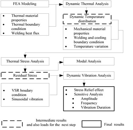
The aim of modal analysis is to obtain vibration modes and resonant frequency with VSR process. Finally stress relief effect is evaluated with dynamic vibration analysis and sensitive analysis is carried out with factors such as vibration amplitude, frequency, duration, which can provide important information for designing of VSR test.
In thermal stress analysis, thermal-plastic stress-strain relationship is given by:
where is stress increment, is elastic or elastic-plastic matrix, is strain increment, is a temperature-related vector, is temperature increment. At elastic region:
where is elastic matrix, is a temperature-related elastic vector, is coefficient of linear expansion and is temperature. At plastic region, material yield condition is assumed to be:
where is yield function and is yield stress function which is related to plastic strain and temperature. Suppose that plastic flow theory, plastic strain increment is expressed by:
where is flow factor. After welding and cooling process, residual stress in the structure is .
When vibration stress is applied at a constant temperature, the stress-strain relationship is:
At plastic region, material yield condition is:
where:
When the sum of and fulfils yield condition, plastic strain appears and residual stress will be released.
3. Welding residual stress simulation
Quartz flexible accelerometer is mainly composed of a capacitance sensor, a permanent magnet torquer and a flexible supported quartz plate which is formed by an integrated micro-machining process. These three parts are assembled finally by a connection ring with the process of laser spot welding at the position of soft magnet, a component of permanent magnet torquer.
The air gap between the capacitance sensor and the permanent magnet torquer constitute a differential sensor which may response the motion of the flexible supported quartz plate and the acceleration of the moving vehicle. Dimension of the air gap and centre point position of quartz plate are two important structure factors for the stability of output parameters, such as null bias, scale factor drift, which may be changed with the release of welding residual stress under vibration environment.
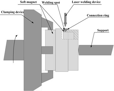
During the welding process, a quartz flexible accelerometer is fixed with a setup at the centre of soft magnet lateral round face and is sheathed by a connection ring, as is shown in Fig. 2. With laser power of 500 W and spot diameter 0.8 mm, connecting ring and soft magnet are welded along the peripheral direction.
Fig. 2Laser spot welding setup
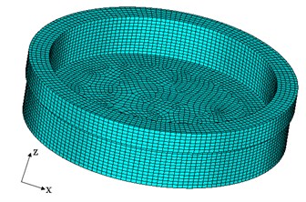
In ANSYS, a symmetric model of connection ring and soft magnet is constructed with fine meshes generated, which is shown in Fig. 3. Thermal coupled analysis is carried out. Solid70 is selected from the ANSYS element library for thermal analysis, while the associated structure solid185 is used for mechanical analysis.
Fig. 3Finite element mesh model
The welded components, connection ring and soft magnet are made of a kind of stainless steel alloy. During welding process, material properties and structure near welding zone will change greatly, with physical phenomenon of plastic deformation, hardening and phase transformation, which is very complicated to describe. As the aim of laser spot process simulation is to leave residual stresses in the welding zone, phase transformation is neglected.
The density, Poisson's ratio, thermal conductivity and coefficient of thermal expansion of the stainless steel alloy are measured in laboratory at room temperature, with the values 8.1×10³ kg/m3, 0.3, 14×10-7 W/m °C and 4.63 °C-1.
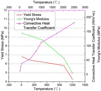
Temperature dependent material properties are also measured which includes Young's modulus and yield stress, the value is shown in Fig. 4.
In thermal analysis two boundary conditions are applied. The first is convective heat transfer coefficient boundary condition at the surfaces that contact with air, which is also changed with temperature as shown in Fig. 4. The second is symmetric boundary at the symmetric plane. In thermal-stress analysis, zero displacement boundary condition at the support position of quartz flexible accelerometer is added, according to Fig. 2.
Fig. 4Temperature dependent material properties of stainless steel alloy and surface convection
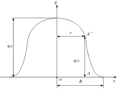
Heat generated from welding process is the load in thermal analysis. Several heat source models are developed to simulate the LSW process, among which the Gaussian model found to be the best agreement with experimental results [14]. Gaussian heat source model is governed by the following equation and is shown in Fig. 5:
where is the maximum density of heat flow at the center of the laser power center, is the effective spot diameter, and is the distance of the point near welding location to laser power center .
Fig. 5Gaussian heat source model
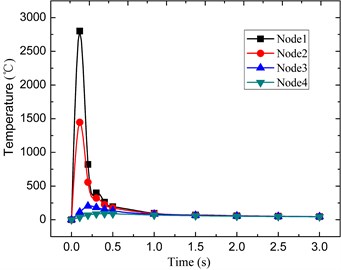
In order to compare residual stress around welding zone, four nodes are selected; each has a different distance from the heat source. Node number 1 is the heat source and node 2 has the distance of 0.448 mm to the node 1, node 3 has the distance of 0.896 and node 4 has the distance of 1.345 to the heat source.
Fig. 6 shows the change of temperature of these four nodes during welding and cooling process. Node 1, which is at the heat source position, has the maximum temperature of 2750 centigrade. Maximum temperature of node 2 is nearly 1500°C, and the other two nodes have lower temperatures compared with node 1 and node 2. After welding, temperature of these nodes is decreased gradually to room temperature.
Fig. 6Temperature of the four nodes around welding zone
In order to evaluate temperature near welding zone, a thermocouple is placed 0.6 mm away from the welding point. Temperature values are recorded and the maximum measured temperature is 403.2 °C, and from numerical simulation the interpolation temperature is 417.3°C, results show measured results have preferable agreement with the simulation results.
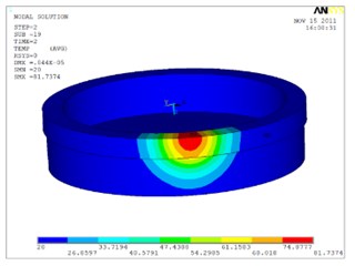
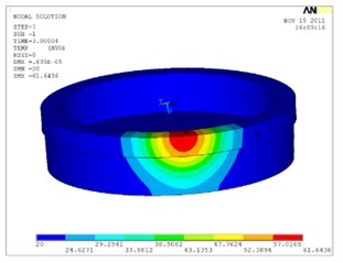
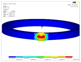
Fig. 7 shows the temperature distribution of the connection ring and soft magnet at different times. During welding process temperature of welding zone increased rapidly, at the time of 0.02 s welding center temperature is 840°C, at 0.06 s it is 2000°C, which means that it reaches melting point of the stainless steel alloy, and after that depth of melting zone keeps on expanding. At the time of 0.1 s the area of melting zone reaches its peak value and the depth covers the connection ring and soft magnet, which is shown in Fig. 8. And that means these two parts are welded.
Fig. 7Temperature distribution at different times during welding and cooling process
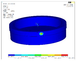
a)
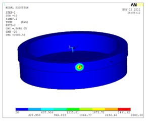
b)
c)
d)
Fig. 9 shows the change of Von-Mises equivalent stress of these four nodes during welding and cooling process. At the time of 0.1 s, node 1 has the maximum stress. When cooling to room temperature, the remaining stress is welding residual stress. At the center of the heat source residual stress has a maximum value of 4.86 MPa.
Fig. 8Cross-section of welding melt zone at time of 0.1 s
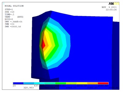
Fig. 9Von-Mises stress of the four nodes around welding zone
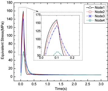
Fig. 10 shows the equivalent stress distribution of the connection ring and soft magnet at different times. At the welding process stress distribution is centralized, while at the cooling process stress value is decreased, residual stress will remain in the welding zone.
Fig. 10Equivalent stress distribution at different times during welding and cooling process
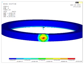
a)
b)
c)
d)
4. Vibration stress relief effect
The setup of vibration stress relief is shown in Fig. 11, where a quartz flexible accelerometer is installed on the upper surface of a clamping device and then fixed to the vibration bench with the direction of vibration . The clamping device is bonding to the external circular face of soft magnet of accelerometer.
In vibration analysis, zero displacement boundaries at the support position in thermal-stress analysis are removed and then applied at the vibration bonding area. For modal analysis no load is applied and results show that the frequency of the first mode is 28036 Hz.
In time-domain dynamic vibration analysis zero displacement boundary condition is applied at the bonding position at the directions of and and at the direction, sinusoidal vibration with the frequency of 28036 Hz and displacement amplitude of 0.8 um is applied with APDL.
Fig. 11Setup of vibration stress relief
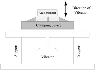
Fig. 12 shows the residual stress distribution of welding centre at different times, from which it can be seen that vibration can greatly decrease the welding residual stresses. And the maximum stress during vibration process is 7.2 MPa; while from Figure 4 the yield stress of connection ring and soft magnet are 6.8 MPa. That means vibration stresses plus residual stresses exceed the yield stress of the material, after vibration residual stress is relieved.
Fig. 12Residual stress distribution of welding centre at different time
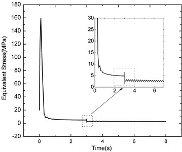
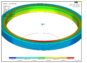
Fig. 13 shows the residual stress value at welding zone before and after vibration. Before VSR the maximum residual stress is 4.86 MPa, and after vibration the value is 2.648 MPa, which is decreased by 45 %.
Fig. 13Residual stress at welding zone after vibration
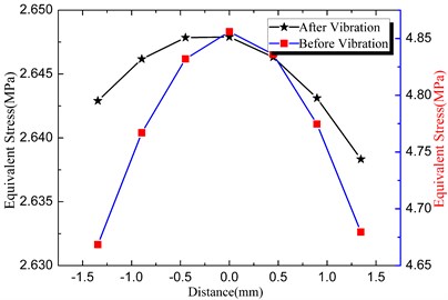
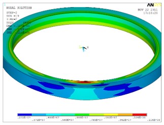
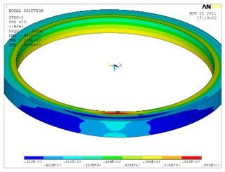
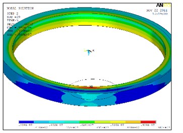
Fig. 14 shows the residual stress distribution at welding zone before and after vibration, from which we can see that VSR can also homogenize the distribution of residual stresses.
Fig. 14Residual stress distribution at welding zone before and after vibration
a)
b)
Due to the dimension limitation of welding spot and lack of precise instrument, it is difficult to obtain residual stress data in the experiment. As mentioned above, with the releasing of residual stresses the structure of the welding zone will deform, which will influence the stability of accelerometer performance parameters, such as null bias and scale factor [15]. Vibration experiments were carried out and the setup is the same as in Fig. 11. Null bias and scale factor data were recorded, and after 300 seconds these two performance parameters tend to fluctuate stably without monotonous changing trend, which indicates that the accelerometer has been in a stable state. However the relationship between accelerometer performance parameter and stress relief effect is yet to be established, results of this experiment can indirectly prove that vibration has effect on the accelerometer residual stress relief.
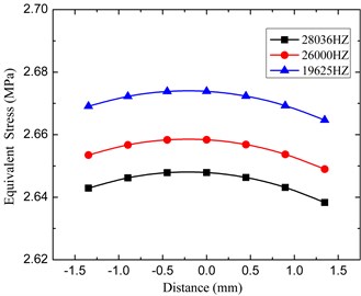
Three groups of vibration conditions are selected to study the effect of vibration factors on residual stress relief. In the first group, sinusoidal vibrations are applied to the accelerometer, with frequencies of 28036 Hz, 26000 Hz and 19625 Hz, amplitude of 0.8 um and duration of 150 cycles. In the second group, vibrations with 28036 Hz, amplitude of 0.8 um, 1.2 um and 1.6 um, and duration of 150 cycles are applied. In the last group, vibrations with 28036 Hz, amplitude of 0.8 um and duration of 150 cycles, 200 cycles and 300 cycles are applied. Among these three parameters, vibration amplitude is the key parameter to provide enough dynamic energy and help the material to turn into plastic state. With the same amplitude, resonant vibration has better stress relief effect than non-resonant vibration, as is shown in Fig. 15. Vibration time is not so important, that is stress relief effect is nearly the same for 150 cycles, 200 cycles and 300 cycles. Results are similar with the results in [11] and [13].
Fig. 15Effect of frequency on VSR
5. Conclusion
Vibration stress relief effect is studied for precise instrument which has small size and where residual stresses are difficult to measure. The following conclusions can be made.
1. Vibration can decrease the welding residual stress of quartz flexible accelerometer, which will make the accelerometer structure more stabilized.
2. Vibration amplitude is the key parameter to provide enough dynamic energy and help the material turn into plastic state.
3. Resonant frequency has very obvious effect on stress relief, vibrations at resonant frequency can relief more residual stress than vibrations at non-resonant frequency.
4. Vibration duration is not a very sensitive parameter for stress relief.
For residual stress on ring structure, torsional vibration might have better relief effect than longitudinal vibration. In our further studies vibration direction, variable frequency vibration effect on VSR effect will be studied and attentions will also be payed to the possibility of fatigue damage to the structure of quartz flexible accelerometer resulting from the VSR process.
References
-
R. Dawson, D. G. Moffat Vibratory stress relief: a fundamental study of its effectiveness. Journal of Engineering Materials and Technology, Vol. 102, 1980, p. 169-176.
-
Luh G. C., Hwang R. M. Evaluating the effectiveness of vibratory stress relief by a modified hole-drilling method. Int. J. Adv. Manuf. Technol., Vol. 14, 1998, p. 815-823.
-
Munsi A. S. M. Y., Waddell A. J., Walker C. A. Modification of residual stress by post-weld vibration. Materials Science and Technology, Vol. 17, 2001, p. 161-165.
-
Munsi A. S. M. Y., Waddell A. J., Walker C. A. Modification of welding stresses by flexural vibration during welding. Science and Technology of Welding and Joining, Vol. 6, Issue 3, 2001, p. 133-138.
-
Munsi A. S. M. Y., Waddell A. J., Walker C. A. Vibration stress relief – an investigation of the torsional stress effect in welded shafts. Journal of Strain Analysis, Vol. 36, Issue 5, 2001, p. 453-464.
-
Rao D., Wang D., Chen L. The effectiveness evaluation of 314L stainless steel vibratory stress relief by dynamic stress. International Journal of Fatigue, Vol. 29, Issue 1, 2007, p. 192-196.
-
Martinson P., Daneshpour S., Kocak M., Riekehr S., Staron P. Residual stress analysis of laser spot welding of steel sheets. Materials and Design, Vol. 30, 2009, p. 331-335.
-
Lars-Erik Lindgren Finite element modelling and simulation of welding. Part 3: Efficiency and integration. Journal of Thermal Stresses, Vol. 24, 2001, p. 305-334.
-
L. Kuang Finite Element Prediction of Residual Stress Relief in a Two-Dimensional Cantilever Beam. A Thesis for Master Degree, Alfred University, 2002.
-
Hahn W. F. Vibratory Residual Stress Relief and Modification in Metals to Conserve Resources and Prevent Pollution. Final Report, Centre of Environmental and Energy Research (CEER), Alfred University, 2002.
-
Zhao X. C., Zhang Y. D., Zhang H. W. Simulation of vibration stress relief after welding based on FEM. Acta Metallurgica Sinica, Vol. 21, Issue 4, 2008, p. 289-294.
-
Kwofie S. Plasticity model for simulation, description and evaluation of vibratory stress relief. Materials Science and Engineering, Vol. 516, Issue 1-2, 2009, p. 154-161.
-
Yang Y. P. Understanding of vibration stress relief with computation modelling. Journal of Materials Engineering and Performance, Vol. 18, Issue 7, 2009, p. 856-862.
-
Eager T. W., Tsai N. S. Temperature fields produced by travelling distributed heat sources. Welding Journal, Vol. 62, Issue 12, 1983, p. 346-355.
-
Dan Xu, Yunxia Chen, Rui Kang Study of accelerated stability test method for quartz flexible accelerometer. IEEE Transactions on Device and Materials Reliability, Vol. 11, Issue 1, 2011, p. 148-156.
About this article
The authors would like to thank Dr. Guo Linrui, for providing of laser welding technological parameters and his assistance with finite element modeling.
