Abstract
At the moment in Lithuanian there is no existing reglamentation dealing with calibration or testing of geodetic angle measuring instrumentation (as theodolites, tacheometers, laser scanners, laser trackers etc.) in full range of its angular measurements. Though calibration and testing of horizontal angle measurements can be performed by multiple methods, calibration of vertical angle measurements still is a serious problem. In the paper a review on possible methodology of calibration and testing of vertical angle measuring instrumentation (like tacheometers, laser scanners etc.) is given together with proposed principles and technical solutions for the calibration.
1. Introduction
Testing and calibration of angle measurement instrumentation can provide the knowledge of both random and systematic (biases) errors of the measures. If determination of random errors of measurements defines the uncertainty of measurements, the determination of systematic errors (or biases) can provide valuable information for increasing the accuracy of measurements by providing (physically or numerically) the corrections of results. Therefore precise determination of systematic errors of measurements is crucial and capable of increasing the accuracy of measurements considerably.
Generally there are several groups of plane angle measurement principles (methods) which could be applied for testing and (especially) calibration of angle measurement instrumentation [1, 2]:
1. Solid angular gauge method:
– polygons (multiangular prisms);
– angular prisms;
– angle gauges, etc.;
2. Trigonometric method (angle determination by means of linear measurements);
3. Goniometric method (plane angle determination by means of a circular scale):
– full circle (limb, circular code scales etc.);
– non-full circle (sector scales).
Nowadays in geodesy, surveying and machine engineering lots of instrumentation relying on precise angle measurements is implemented. These instruments are: theodolites, tacheometers, total stations, laser scanners, laser trackers etc. The accuracy of measurements of these instruments relies on precise determination of both horizontal and vertical angle measures. Since angle encoders implemented in mentioned instruments (same as the entire system) can produce significant errors in measurement, these angle measuring instruments should be thoroughly tested and calibrated. Calibration and testing of angle measuring instruments has always been a serious problem and if calibration of the horizontal angle measurements could be quite efficiently accomplished using standard precise turn tables (quite widely implemented in metrology and industry), calibration of vertical angle measures required some special instrumentation [3-5]. Additionally since modern angle encoders implemented in the measuring instrumentation produce a huge number of angle measures a calibration in the entire range of angle measures is also required.
Presently a standard outlining the testing of angle measuring instrumentation is available. Such testing determines only the uncertainty of angle measures in certain very limited angular positions, thus practically determining only the random error of measures by testing the repeatability. Such testing cannot ensure the reliability of measures. The equipment capable of determining the precise systematic errors of the measures and therefore determining the true angle values is usually operated by large instrumentation producing or implementing companies and is not available for wide public.
Further in this paper we present several cost-effective methods of possible vertical angle calibration, with some of the results of the real measurements.
2. Principle of calibration of vertical angle measures
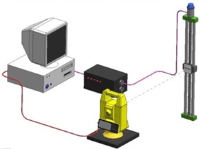
Calibration of vertical angle measures of the geodetic instruments was usually performed by a special bench composed of autocollimators attached at the different vertical angles to the calibrated instrument and mirror (which autocollimators pointed to) attached to the telescope of the instrument, in this case the entire test bench used to be extremely bulky and able to measure only very limited number of vertical angles [4]. A new approach to the problem was implementation of the precise angle encoder for the creation of vertical angle reference, in this case it was possible to create unlimited number of reference angle values, but the equipment was extremely expensive [6-8]. One of the projects of similar equipment allowing high accuracy calibration of vertical angle measures is shown in Fig. 1.
Fig. 1Arrangement of instrumentation for calibration of vertical angle measures of geodetic instruments
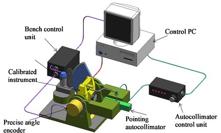
Test bench shown in Fig. 1 can be implemented for testing and calibration of vertical angle measures with high precision (depending on the mechanical structure, encoder and positioning autocollimator used), nonetheless such arrangement is extremely expensive due to high cost of instrumentation and manufacturing of high accuracy mechanical equipment [9-10].
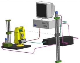
To decrease the complexity of equipment required (thus increasing the needed input from the operator) a method of calibration of vertical angles of geodetic equipment implementing trigonometric methods was proposed (Fig. 2).
In case shown in Fig. 2 the vertical angle measure is derived from the precise linear bar, with telescope being collimated manually by operator. That way the precise calibration of vertical angle measurements can be done implementing relatively inexpensive and widely available equipment.
Nonetheless the greatest difficulty in case of such calibration is precise determination of the distance from rotation angle of the telescope to linear bar. This distance cannot be measured by simple means due to practically unknown nature of the mechanical attachment of telescope [11]. To solve the problem a method of determination of distance by means of precise movement of instrument under testing to determined position with repeated scale measurements was developed.
The principle of proposed vertical angle calibration is based on the trigonometric angle determination. The arrangement for calibration is shown in Fig. 3.
Fig. 2Arrangement for calibration of vertical angle measures implementing trigonometric methods
Fig. 3Arrangement for vertical angle calibration for geodetic instruments
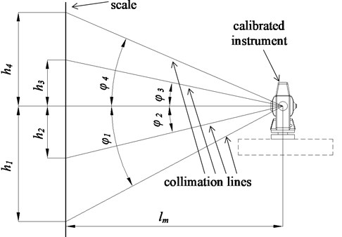
As can be seen from the picture an instrument to be calibrated is placed at a certain known distance (, Fig. 3) from the precise linear scale. The spyglass of the instrument is declined at the angle (, , or ) accuracy of which must be calibrated. The reading (, , or ) from the scale is taken. The angle of interest is expressed:
where – the reading from the scale, – distance from the instrument’s center to the reading surface of the scale.
It is difficult to measure with high accuracy, so additional measures must be taken for the calculations. It is accomplished by adding the known length measure of high accuracy. It can be the end gauge, linear incremental transducer, etc. On the second step the instrument is replaced on the distance () from the scale preserving the same value of instrument’s view angle. The position of horizontal axis is replaced from the point to the position .
For the precise vertical angle measurements the distance from calibrated instrument (tacheometer) and the reference measure (linear scale) has to be determined quite precisely (down to 0.01 mm).
The determination of the distance from calibrated instrument to the reference measure can be determined using the layout shown in Fig. 4. The distance from instrument calibration position (0) to the reference measure (scale) can be calculated by moving the instrument linearly to the subsidiary positions (1, 2) while the same vertical angle ( or ) of the calibrated instrument spyglass is being kept. Therefore the readouts of the vertical scale at the same vertical angle and different length to the scale can be made and distances , and thus can be determined. The calibrated instrument should move from position 0 to positions 1 and 2 by means of some kind of guide-skid, and the linear movement ( and ) determined using the linear photoelectrical scale, laser interferometer or even precise linear optical scale (with microscope).
Fig. 4Determination of the distance from calibrated instrument to the reference measure; 0 – instrument calibration position, 1, 2 – subsidiary calibrated instrument position used for distance determination
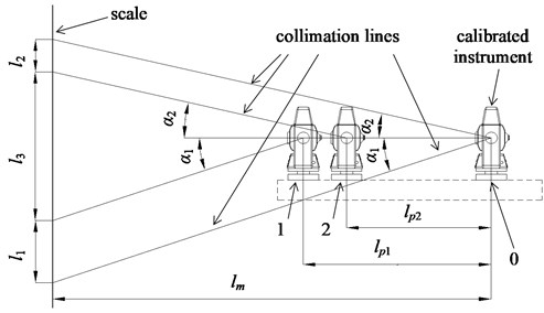
To determine the distance calibrated instrument at the calibration position 0 should be pointed at the certain scale stroke with the vertical angle and scale readings taken. After that instrument is moved to the position 1 keeping the same vertical angle till the spyglass collimated to different scale stroke, thus scale distance determined. After that instrument moved back to the position 0 and collimated to the different scale stroke with vertical angle , the measurement procedure is repeated thus the distance determined. Distances and will usually be different since it is almost impossible (in case of visual scale) to collimate exactly to the scale stroke (having different vertical angles and ) having the same horizontal movement. The procedure of two measurements ( and ) is essential since it is also almost impossible (again in case of simple visual scale) to collimate the tacheometer at the horizontal collimation line to a certain scale stroke.
Having the mentioned measurements performed the vertical angles can be determined (using linear measures, Fig. 3):
and:
where , – scale measures at the same vertical angle but different linear distance from calibrated instrument to the reference scale; , – linear movement of instrument during measurements.
Also the total measured length of the scale could be expressed (Fig. 1):
where – distance from the calibrated instrument to the reference scale.
Therefore the real distance form calibrated instrument to the scale:
Using equations (2) and (3) it could be written:
Therefore the real distance from calibrated instrument to the reference scale can be determined using only linear scale.
After the precise distance to the linear reference (linear bar) was determined a simple trigonometric method of angle measurements can be performed. This way practically unlimited number of vertical angle measures can be tested (calibrated) overviewing entire range of vertical angle encoder values of the instrument. The accuracy of calibration therefore depends on the accuracy of reference bar and accuracy of pointing of telescope to the specific dash of the bar (therefore the qualification of human operator).
Such arrangement allows simple and cost-effective calibration of vertical angle measures with accuracy high enough.
3. Laboratory arrangement
The described principle of vertical angle measurements was tested at Institute of Geodesy, VIilnius Gediminas Technical University. The arrangement of instrumentation for measurements is shown in Fig. 5.
For precise measurements of horizontal displacements of the instrument high accuracy two axis horizontal table (Fig. 5) was used (ensuring accuracy of movement of up to 1 µm). The industrial laboratory linear scale of high accuracy of 1 m in length with the scale strokes at every 1 mm was used. After the measurement and calculation of linear distance from tacheometer to the scale performed according to the previous chapter, it was determined that the distance equals to 2.4215 m.
The main objective of experiment was to test the calibration method and obtain preliminary results of the systematic errors (biases) of the vertical angle measurements using Trimble 5503 tacheometer [12].
The calibration was performed using 1 m precise linear scale collimating the spyglass to the scale strokes at a pitch of 10 mm and 12 mm. The resulting calculated deviations of tacheometer readings are shown if Fig. 6 (10 mm pitch).
As can be seen from Fig. 6 some of the systematic errors of vertical angle measures can be noted, though more serious and thorough analysis of results is needed. By determination of accurate systematic errors across the range of vertical angle measurements and later numerical removal of determined errors (biases) the accuracy of instrument can be substantially increased.
4. Possibilities for further development of the instrumentation
The method of vertical angle calibration described above due to purely manual nature of measurements is quite time consuming and additionally imposing human (operator) errors, which are often quite hard to overcome. For further implementation of described method automation should be developed. Several types of possible automation of the equipment are given in Fig. 7.
Fig. 5Arrangement for automated vertical angle measurements calibration
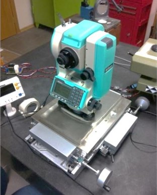
Fig. 6Deviations of vertical angle readings taken at the linear pitch of 10 mm
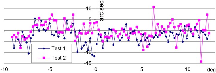
Fig. 7Possible arrangement for automated/semi-automated vertical angle measurements calibration: a) arrangement with automated pointing mark positioning, b) arrangement with automated telescope movement
a)
b)
In Fig. 7a, possible arrangement with minimal level of automation is given, in this case the linear (vertical) reference is realized by means of mechanically movable dash linear movement of which is determined by linear encoder. This way the errors due to pointing accuracy to multiple dashes can be eliminated.
Further, in Fig. 7b, an arrangement with automated movement of the telescope is given. In this case a special scanning CCD camera (or CCD line) tracking the movement of the dash is attached to the telescope, with telescope movement being realized by special mechanical arm. This way a full automation of the calibration process with elimination of operator errors could be guaranteed.
5. Conclusions
1. A simple method of calibration of vertical angle measurements accuracy of geodetic instruments was proposed, similar method of angle measurement calibration could be implemented for all angle measurements, both vertical and horizontal of collimated instruments such as theodolites, tacheometers, etc.;
2. Possibilities of calibration of vertical angle measures were demonstrated implementing available cost-efective instrumentation;
3. Initial results of calibration of vertical angle measurements are given;
4. Due to manual nature of present measurements some operator caused errors can be expected. Therefore a further development of automation of process is essential.
References
-
Giniotis V., Rybokas M., Petroškevičius P. Investigations into the accuracy of angle calibration. Geodesy and Cartography, Vol. 3(30), 2004, p. 65-70.
-
Walser B. H. Development and Calibration of an Image Assisted Total Station. Dissertation, Zurich, ETH, 2004, 190 p.
-
Ingensand H. A new method of theodolite calibration. XIX International Congress, Helsinki, Finland, 1990, p. 91-100.
-
Giniotis V., Šiaudinytė L., Bručas D. Arrangement for vertical angle calibration of geodetic instruments. Mechanika, 2009, Vol. 5(79), p. 59-62.
-
ISO 17123-5:2005. Optics and Optical Instruments – Field Procedures for Testing Geodetic and Surveying Instruments. Part 5: Electronic Tacheometers. Geneva, ISO, 2005, 11 p.
-
BIPM, IEC, IFCC, ISO, IUPAC, OIML. Guide to the Expressions of Uncertainty in Measurement. ISO Publishing, 1995.
-
Bručas D., Giniotis V. Modified circular scale testing and calibration method. Proceedings of the 7th International Conference “Environmental Engineering”, Selected Papers, Vol. 3, Vilnius, Lithuania, Technika, 2008, p. 1269-1273.
-
Lichti D., Gordon S., Tipdecho T. Error models and propagation in directly georeferenced terrestrial laser scanner networks. J. Surv. Eng., Vol. 131(4), 2005, p. 135-142.
-
Large A., Heritage G. Ground Based LiDAR and Its Application to the Characterisation of Fluvial Forms. 2012, p. 323-339.
-
Sakimura R., Maruyama K. Development of a new generation imaging total station system. J. Surv. Eng., Vol. 133(1), 2007, p. 14-22.
-
Scherer M., Lerma J. L. From the conventional total station to the prospective image assisted photogrammetric scanning total station: comprehensive review. Journal of Surveying Engineering, Vol. 135(4), 2009, p. 173-178.
About this article
This research is funded by the European Social Fund under the Project No. VP1-3.1-ŠMM-07-K-01-102.
