Abstract
Prefabricated construction is a structural form vigorously developed by the country and is the inevitable path for the sustainable development of the construction industry. In order to enhance the seismic performance of prefabricated concrete frame structures, concealed steel angle connections for prefabricated frame beams and columns are employed. Based on experimental research on the force performance of these connection nodes, a finite element model of the connection node is established using ABAQUS software to analyze the influence of design parameters on the force performance of the specimen. The analysis indicates that upgrading the concrete grade from C25 to C55 increases the positive bearing capacity by 12.3 %. The specimen’s energy dissipation capacity and stiffness are both improved. Increasing the thickness of the steel cover plate can enhance the specimen's bearing capacity, stiffness, and energy dissipation capacity. Increasing the angle steel thickness from 4 mm to 10 mm results in a 27.78 % increase in negative bearing capacity, consequently enhancing the specimen’s energy dissipation capacity. By increasing the bolt diameter from 16 mm to 24 mm, the positive bearing capacity increases by 8.2 %, and the negative bearing capacity increases by 10.9 %. The energy dissipation capacity and stiffness of the specimen also improve accordingly.
1. Introduction
Prefabricated structure is a new type of structural system that the state vigorously develops [1, 2]. It is one of the important means to improve the development level of the construction industry and promote the development of sustainable buildings [3]. For the assembled concrete frame structure, the beam-column connection node plays a decisive role in the seismic performance of the structure [4, 5]. In view of the fact that the research on the performance of the beam-column joints of the assembled concrete frame is mostly experimental research at home and abroad, there is a lack of reliable and effective nonlinear finite element analysis. Therefore, it is urgent to establish a reliable and effective assembly node model and conduct more in-depth research on seismic performance.
As a new type of joint connection form, the prefabricated frame beam-column concealed corbel angle steel connection joint is tested and studied by our research group under low cyclic loading. The results show that the joint has good seismic performance. In order to further explore the mechanical performance of the joint, the mechanical performance of the assembled joint is numerically simulated and analyzed based on the large-scale general finite element software ABAQUS. The simulation results are compared with the test results to verify the influence of test parameters on the seismic performance of the specimen. By changing the design parameters, such as the thickness of steel cover plate, concrete strength, bolt diameter, angle steel thickness, etc., the influence of each parameter change on the mechanical performance of the joint is analyzed, so as to verify the correctness and reliability of the assembled joint model. In this paper, the specimen SJ-3 in Reference [6] is selected as the comparison model for finite element analysis. SJ-3 and all the test data in this paper are from Reference [6].
The rest of the paper will be organized as follows. Firstly, we presented the establishment of a finite element model for the concealed haunch angle steel joint of an assembled frame beam-column. In the third section, we compared the finite element simulation results with the experimental results. In the fourth section, based on the finite element model, we conducted a parameter analysis of the angle steel joint. In Section 4, it is the conclusion.
2. Prefabricated framed concealed angle steel connection joint finite element model
2.1. Outline of the proposed method
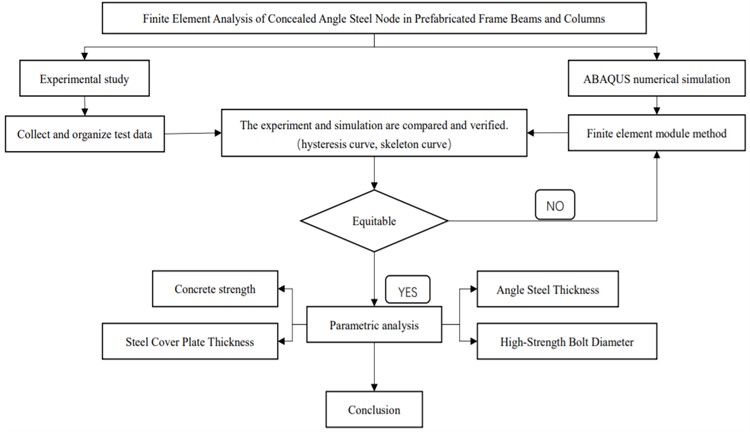
Fig. 1Outline of the proposed method
2.2. Constitutive model for concrete
As shown in Fig. 2 [8], the concrete adopts a plastic damage model based on the constitutive relationship specified in the “Code for Design of Concrete Structures” [7]. The compressive and tensile damage factors of concrete are calculated based on the Sidiroff energy equivalence principle [8]. Using these two damage factors, the unloading path and stiffness degradation can be determined. The compressive stiffness recovery coefficient is taken as 1, and the tensile stiffness recovery coefficient is taken as 0.
Fig. 2Concrete plastic damage model
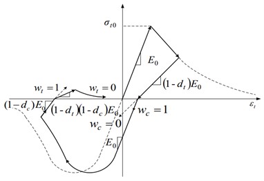
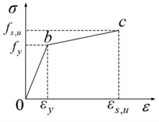
Fig. 3Double line model
2.3. Constitutive relationship for reinforcement and steel materials
In this study, both reinforcement and steel materials are modeled using a bi-linear kinematic hardening model to simulate their nonlinear behavior, as shown in Fig. 3. The slope of the hardening segment is taken as 1 % of the elastic modulus, and the Poisson’s ratio is assumed to be 0.3. It is necessary to convert the nominal stress-strain relationship obtained from the experiments to the true stress-strain relationship, and the two are related by the following equation, refer with: Eq. (1-2) [9]:
where: and are the nominal stress and strain of the material, respectively. and are the true stress and strain of the material.
2.4. Meshing
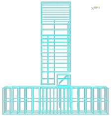
As shown in Fig. 4, in this model, the notch beams, columns, bolts, angle steel, embedded steel plates, steel cover plates, and washers are all meshed using solid elements (C3D8R). The reinforcement is represented using two-node three-dimensional linear integral elements (T3D2).
Fig. 4Main components after meshing
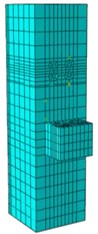
a) Prefabricated concrete columns (C3D8R)
b) Steel reinforcement framework (T3D2)
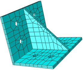
c) Angle steel (C3D8R)
3. Finite element analysis results analysis
The hysteresis curve of test specimen SJ-3 [6] in the experiment closely matches the simulation, as shown in Figure 5. Both exhibit low energy dissipation in the early loading stages, which increases with the growing load. After specimen yielding, the unloading stiffness in the simulation is smaller than that in the experiment. This is mainly due to the fact that the simulation does not consider the bond slip between the steel reinforcement and the concrete. On the hysteresis curve, this is manifested as unloading stiffness being greater than the actual unloading stiffness.
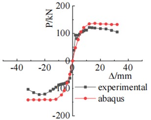
The skeleton curves derived from experimental and simulation data exhibit a basic resemblance. The experimental specimen's skeleton curve shows a descending segment in the later stages of displacement loading, which is not as pronounced in the simulation. This is primarily because the concrete material of the experimental specimen is hand-mixed and its material uniformity is far from that of the finite element model. As shown in Fig. 6, the positive bearing capacity of test specimen SJ-3 differs by 15.59 KN between the experiment and simulation, with an error of 12.80 %. The negative bearing capacity differs by 20.85 KN, with an error of 17 %. The errors in both positive and negative bearing capacities do not exceed 17 %. Overall, the experimental and simulation load-bearing capacities and their trends remain largely consistent, confirming the reliability of the finite element model.
Fig. 5Hysteresis curve of test results and simulation results
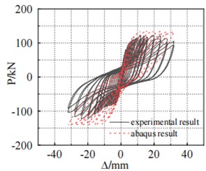
Fig. 6Comparison chart of skeleton curve between test results and simulation results
4. Analysis of force performance parameters based on finite element model
Based on the finite element research in Section 3, the study analyzes the impact of factors such as concrete strength and steel cover plate thickness on the load-bearing performance of the specimen, using SJ-3 as the reference model.
4.1. Influence of concrete strength grade
The concrete grade was upgraded from C25 to C55, wherein the positive load-bearing capacity increased from 120.02 kN to 134.62 kN, showcasing an improvement of 12.3 %, as illustrated in Fig. 7(a). The energy absorption capacity of the specimens also increases with the increase in concrete strength. However, after reaching concrete strength grade C45, the improvement in energy absorption capacity becomes smaller, as depicted in Fig. 7(b). The stiffness of the specimens increases with the rise in concrete strength grade, as indicated by the comparison curve in Fig. 7(c).
Fig. 7Comparison chart of different concrete strengths with corresponding curves
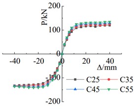
a) Skeleton curve comparison chart
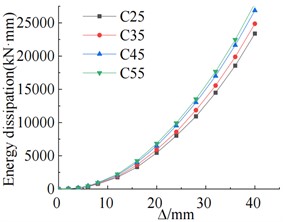
b) Cumulative energy consumption
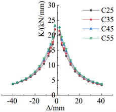
c) Stiffness degradation comparison chart
4.2. Influence of steel cover plate thickness
From Fig. 8(a), it can be observed that increasing the thickness of the steel cover plate significantly improves the load-carrying capacity of the specimen when the thickness is less than 10 mm. However, once the thickness reaches 10 mm, the increase in load-carrying capacity becomes less significant. The energy dissipation capacity of the specimen increases with the increase in steel cover plate thickness, especially during the elastic-plastic stage after yielding, as shown in Fig. 8(b). The comparison in Fig. 8(c) indicates that the stiffness of the specimen increases with the increment of steel cover plate thickness. The stiffness degradation pattern of specimens with different steel cover plate thicknesses is similar.
Fig. 8Chart of different steel cover plate thicknesses with corresponding curves
a) Skeleton curve comparison chart

b) Cumulative energy consumption
c) Stiffness degradation comparison chart
4.3. Influence of angle steel thickness
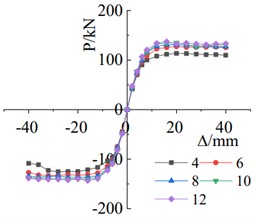
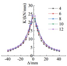
As shown in Fig. 9(a), when the thickness of the angle steel increases from 4 mm to 10 mm, the positive load-carrying capacity increases by 3.42 %, while the negative load-carrying capacity increases by 27.78 %. The cumulative energy dissipation of the specimen increases with the increment of angle steel thickness, indicating an enhancement in energy dissipation capacity, as depicted in Fig. 9(b). The comparison in Fig. 9(c) demonstrates that increasing the angle steel thickness primarily affects the negative stiffness of the specimen, with almost no impact on the positive stiffness. A larger angle steel thickness results in a higher negative stiffness of the specimen.
Fig. 9Chart of different angle steel thicknesses with corresponding curves
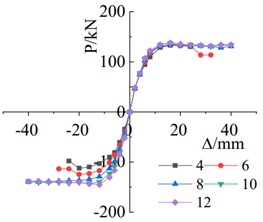
a) Skeleton curve comparison chart
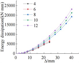
b) Cumulative energy consumption
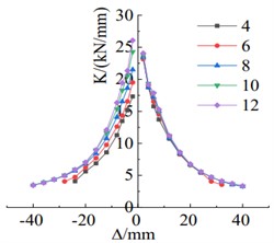
c) Stiffness degradation comparison chart
Fig. 10Chart of different bolt diameters with corresponding curves
a) Skeleton curve comparison chart
b) Cumulative energy consumption
c) Stiffness degradation comparison chart
4.4. Influence of high-strength bolt diameter
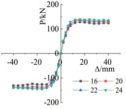
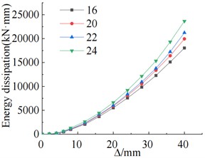
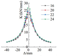
As shown in Fig. 10(a), with the bolt diameter increased from 16 mm to 24 mm, the positive load-bearing capacity increased from 128.20 kN to 138.76 kN, resulting in an improvement of 8.2 %. Similarly, the negative load-bearing capacity increased from 131.56 kN to 145.86 kN, showcasing a rise of 10.9 %. With these changes, both the positive and negative yielding displacements of the specimens were reduced. The energy dissipation capacity of the specimen improves with the increase in bolt diameter, as illustrated in Fig. 10(b). The comparison in Fig. 10(c) reveals that as the bolt diameter increases, the stiffness of the specimen gradually increases, and the trend of stiffness degradation remains relatively consistent.
5. Conclusions
This article establishes a finite element model of concealed steel angle connections for prefabricated frame beams and columns that corresponds to the experimental setup and conducts finite element analysis. The main innovations are as follows:
1) By comparing the results obtained from experiments with those obtained from simulations (hysteretic curves, skeleton curves), it is found that the two agree well, validating the reliability of the finite element model.
2) Parameter analysis of the concealed steel angle connection for prefabricated beams and columns reveals the following: Upgrading the concrete grade from C25 to C55 increases the positive bearing capacity by 12.3 %. The specimen's energy dissipation capacity and stiffness are improved, but at the same time, the yield displacement of the specimen is slightly advanced. Increasing the thickness of the steel cover plate enhances the specimen's bearing capacity, stiffness, and energy dissipation capacity. Increasing the angle steel thickness from 4 mm to 10 mm results in a 27.78 % increase in negative bearing capacity, thereby enhancing the specimen’s energy dissipation capacity. By increasing the bolt diameter from 16 mm to 24 mm, the positive bearing capacity increases by 8.2 %, and the negative bearing capacity increases by 10.9 %. The energy dissipation capacity and stiffness of the specimen improve as the tensile bolt diameter increases.
References
-
Q. J. Jiang, “An overview of the development of prefabricated concrete buildings at home and abroad,” Building Technology, Vol. 41, No. 12, pp. 1074–1077, 2010.
-
T. C. Gu, “The development status of prefabricated buildings at home and abroad,” Standardization of Engineering Construction, Vol. 189, No. 8, pp. 48–51, 2014.
-
M. Mulyono, V. Sampebulu, Nasruddin, and Hartawan, “Quick, easy and exact prefabrication structural module,” in IOP Conference Series: Earth and Environmental Science, Vol. 1157, No. 1, p. 012014, Apr. 2023, https://doi.org/10.1088/1755-1315/1157/1/012014
-
K. Roy, H. Rezaeian, D. Lakshmanan, Z. Fang, G. Beulah Gnana Ananthi, and J. B. P. Lim, “Structural behaviour of cold-formed steel T-Stub connections with HRC and screws subjected to tension force,” Engineering Structures, Vol. 283, p. 115922, May 2023, https://doi.org/10.1016/j.engstruct.2023.115922
-
H. Unterweger, M. Kettler, and P. Zauchner, “Calibrated design model for the compression capacity of angle members – Consideration of welded or bolted joint configurations,” Steel Construction, Vol. 15, No. 4, pp. 255–267, Nov. 2022, https://doi.org/10.1002/stco.202200023
-
Z. Li, C. Qiao, M. Shi, L. Qiao, and X. Chen, “Experimental Study on Seismic Behaviour of Angle Steel Connections with Concealed Corbel of Fully Assembled Frame Beam and Column,” in IOP Conference Series: Earth and Environmental Science, Vol. 719, No. 2, p. 022056, Apr. 2021, https://doi.org/10.1088/1755-1315/719/2/022056
-
“GB50010-2010, Code for design of concrete structures,” China Building Industry Press, Beijing, 2015.
-
J. W. Guo and B. Xu, “Study on the value and application of damage factor of concrete damage plasticity model,” Journal of Gansu Sciences, Vol. 31, No. 6, pp. 88–92, 2019.
-
J. F. Cao and Y. P. Shi, “ABAQUS finite element analysis of common problems,” Mechanical Industry Press, Beijing, 2009.
About this article

The authors have not disclosed any funding.
The datasets generated during and/or analyzed during the current study are available from the corresponding author on reasonable request.
The authors declare that they have no conflict of interest.
