Abstract
When the beamforming algorithm is used to locate the fault of the internal structure, the effective fault acoustic signal will be reflected by the structure shell during its transmission process. This results in the microphone signals being polluted, and then the positioning accuracy being low. In this paper, a phase-shifted beamforming algorithm is proposed to segment the microphone signal, extract the time delay of the reflected noise by using the cross correlation property, and then subtract the reflected noise from the raw data to obtain the microphone signal with weakened reflected signal. The newly generated signals are utilized to calculate the cross-spectral matrix of beamforming, which is then used to locate vibration faults. Simulation results show that the phase-shifted beamforming algorithm can more accurately locate the vibration faults of reflective structures.
Highlights
- Denoising strong reflection noise from the raw signal of near-field microphone array
- A phase-shifted beamforming algorithm based on the time delay property of cross correlation
- Fault location method for dual rotor structure with common cavity under time-varying speed
1. Introduction
Acoustic array beamforming is a non-contact, near-field, and far-field localizable noise technique that has remarkable effects in many fields. However, in vibration fault diagnosis, when compared with contact means such as accelerometers and displacement sensors, the acoustic array signal is highly susceptible to the pollution of reflected noise, including environmental background noise and structure noise. Especially for near-field fault locations of structures with small acoustic reflective components, where the reflection is strong and the microphone array is very close to the structure, this drawback will be more evident because the fusion of structure noise and effective fault source is powerful.
To reduce the impact of reflected noise, many beamforming noise reduction methods have been developed, which are summarized into three main categories: the first one is the improvement of the microphone array arrangement method; the second proceeds from the theoretical basis of beamforming, i.e., Cross-Spectral Matrix (CSM) of the acoustic array signal, to denoise the CSM; the third category is the purification of the acoustic array test signal itself.
Microphone array arrangement methods include regular geometry, random, and spiral. Regular geometrical shapes are usually cross [1], circles, or multi-circle shapes arrays [2]. These arrays are simple in shape, but the intrinsic geometrical regularity causes aliasing and ghost patterns in the acoustic maps. Random arrays can suppress sidelodes on cloud maps but are less capable of identifying symmetrical sound sources. The spiral design array is currently considered the optimal acoustic array [3]. Through array optimization, the localization of complex sound sources, such as broadband and multiple sources, can be obtained by fewer microphones with very low noise in the output maps.
CSM denoise method includes functional beamforming [4], Diagonal Subtraction [5], Sparse & Low-Rank Decomposition [6], Deconvolution Approach for the Mapping of Acoustic Sources (DAMAS) method [7], and CLEAN [8-9]. The functional beamforming performs fractional order degradation of the characteristic values of the CSM, so as to reduce the effect of sidelodes interference and improve the chance of detection for low-power sources. The Diagonal Subtraction treats CSM as a positive-definite Hermitian matrix, the eigenvalues of the array matrix form a diagonal matrix after CSM decomposition. One can mark each value as a source or noise eigenvalue of the vibration, when the noise eigenvalues are denoised and only a few source eigenvalues with large amplitude are retained, the progress can reduce the number of effective sources and suppress false source through the eigenvalue subtraction. Sparse & Low-Rank Decomposition does not require the CSM matrix to be positive-definite; it decomposes the CSM matrix into a diagonal matrix CSLRD with low rank and a sparse noise matrix C-CSLRD, to seek the minimum value of the F-parameter by gradient descent. DAMAS is a widely used beamforming algorithm. This algorithm can refine the sound source localization location with fewer sensors. By using virtual sources to extend the source search location and gridding the possible source locations, DAMAS seeks the sound source location with grid accuracy as the minimum localization deviation rather than acoustic sensor spacing. In the DAMAS location processes, reasonable steering factors need to be established for every virtual source. CLEAN decomposes the CSM into a “clean,” and a “dirty” part, a weighted iterative algorithm that progressively rejects the contaminating noise is applied to the case where the sidelodes noise is spatially coherent with the primary oscillator source.
There are also many ways to denoise the test signal itself; FFT (Fast Fourier Transform) [10], segment-averaged method [11-12], sub-window time domain method [13], acoustic modal analysis method [14], and the Bayesian maximum likelihood method [15-16] all belongs to this class. FFT is the most basic denoising method. The IFFT filtering can get only the interesting band signal and reject other band pollution. The segment-averaged method separates the effective tonal signal and the broadband ambient noise signal in the acoustic signal by segmentally averaging and phase shifts. The sub-window time domain method is a time-frequency signal analysis method, and the algorithm has superior localization capability for vibration sources that vary with the time history. The acoustic modal analysis method plots each source node's vibration pattern by modal analysis, the primary source location can be obtained according to the vibration pattern from frequency domain coherence function between two acoustic signals. The Bayesian maximum likelihood method is a statistical search algorithm with good results for moving sound sources.
However, for the near field fault location of complex structures with strong reflective noise, such as the inner rotor fault location of a dual rotor structure with common cavity under time-varying speed, further research is needed on the above three categories of methods. The layout space of the acoustic array is limited by the size of structural components and near field distance requirements, which makes it difficult to optimize the acoustic array; the CSM denoising principle is based on eigenvalues (representing the characteristic frequency), which makes it difficult to filter out reflected noise because of its same frequency as the working frequency; the existing methods for denoising test signals themselves, although widely applied in both frequency domain and time-frequency domain, lack specialized research on filtering strong reflection noise at time-varying operating frequencies (rotor speed).
In this paper, a beamforming algorithm is developed for the near-field acoustic array with strongly reflected noise by test signal purification. The raw test signal is segmented and the adjacent piecewise signals are correlated so as to obtain the delayed time of the reflected signal. Then the piecewise signals are phase shifted by the time delay length. The reflected signal is extracted and filtered out, and the sound source localization problem, which involves an acoustic reflection structure, will be solved. Finally, a simulation example is provided to demonstrate the effectiveness of the algorithm proposed in this paper.
2. Notation and goal
As a lossless vibration source location algorithm, beamforming algorithm is widely used in the field of vibration fault detection of rotating machinery. The theoretical basis of beamforming is the acoustic array CSM. This section gives the beamforming algorithm flow, and deduces the impact of reflected noise on the CSM.
2.1. Beamforming algorithm
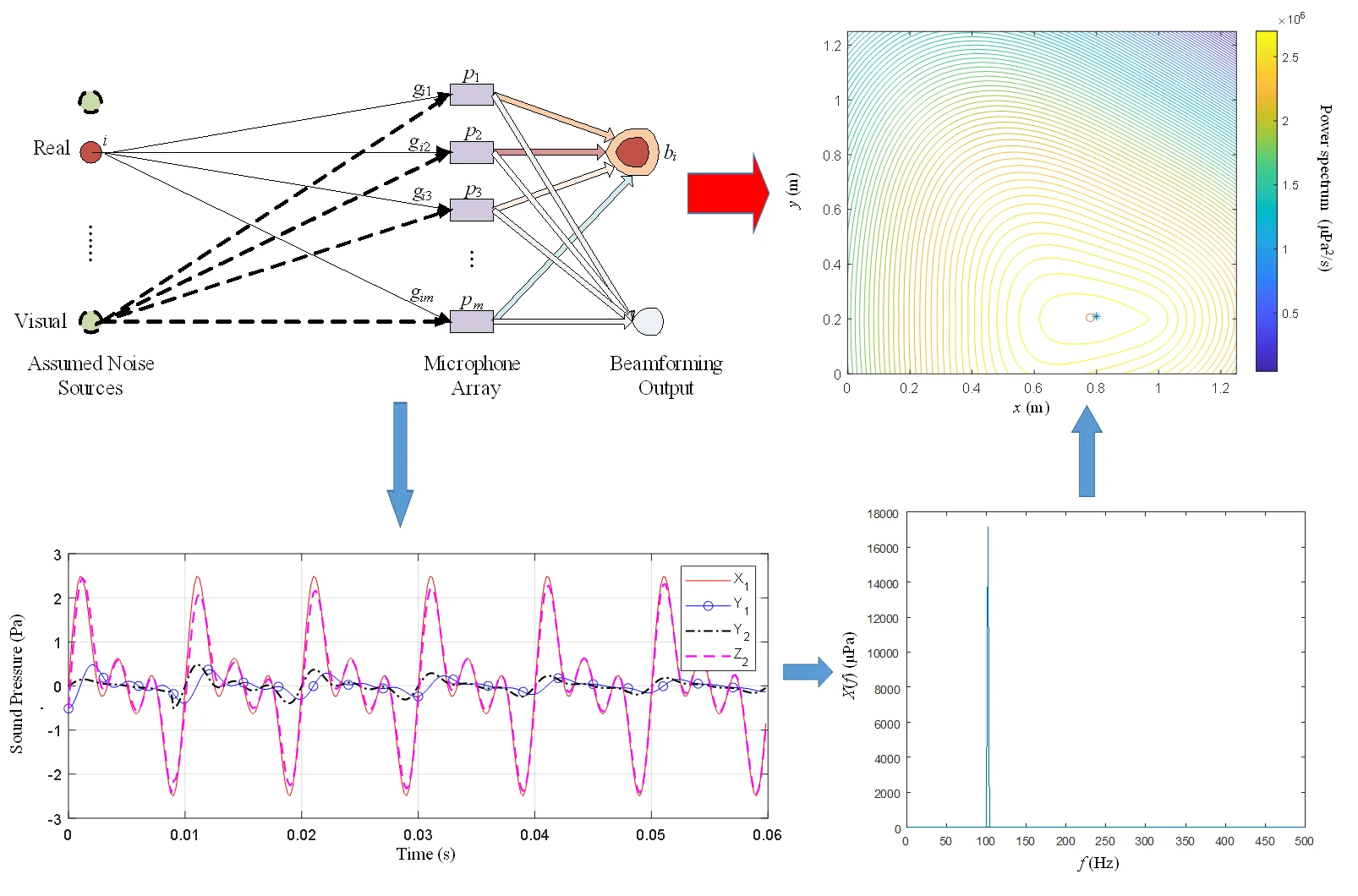
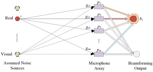
The beamforming algorithm limits the possible position of the sources to a certain area and divides the grid into this area to form the source position scan nodes. The nodes contain the real source and virtual source, then use several microphones to create an acoustic array to collect the sound pressure signal from the source in different directions, and utilize the acoustic array cross spectrum algorithm to scan each node in turn to obtain the sound power map of the whole grid. Finally, the location of the source is identified according to the acoustic power level.
Fig. 1 shows the beamforming localization algorithm for a linear array.
Fig. 1Beamforming algorithm
If microphones are used to form an acoustic array, the CSM of the acoustic array can be defined as:
where – the acoustic spectrum matrix; – the cross spectrum of the -th microphone and the -th microphone, 1, 2,..., , 1, 2,..., ; for the -th source, define the steering vector of the array as:
where – distance from the -th microphone to the center of the microphone array; – distance from the -th source to the -th microphone; – imaginary number sign; – source frequency; – the propagation time of the sound from the -th source to the -th microphone is , is the speed of sound propagation in the air. This paper takes 340 m/s.
The output value of the -th source by beamforming is:
According to the theory of beamforming, if a node is the location of the real source, the output of the beamforming of Eq. (3) is maximum. In contrast, at other places, the beamforming output is small.
2.2. Effect of reflected noise
If the microphone signal contains reflected noise, the acoustic spectrum matrix in Eq. (1) is transformed into:
Thus, Eq. (1) becomes:
Comparing Eq. (1) and Eq. (5) shows that reflected signals introduce noise in the cross spectrum array, affecting the positioning accuracy of the beamforming.
To weaken the structural reflection noise and improve the fault location accuracy, a phase shift beamforming algorithm is designed to resample each sound pressure sensor signal so as to reduce the reflection noise. In this paper, the phase shift algorithm is illustrated with a rotor structure which contains reflective component in itself.
3. Phase-shifted denoising algorithm
Many references have shown that cross-correlation algorithm can obtain the time delay (advance or lag) relationship between two signals expressed in the vibration signal through the phase. Therefore, the phase offset relationship between two signals can be obtained through the time delay. The microphone signal is a composite signal of the actual vibration signal superimposed with the structure’s reflected noise, which is the signal after the time delay of the former. The phase shift of the reflected noise can be calculated using the cross-correlation method, and one can weaken the influence of the reflected noise on the actual signal by extracting the reflected signal from the sound pressure signal.
Set the sampling frequency to , if a microphone acquires a signal of:
Segment the whole microphone’s signal and carry out correlation calculations only for adjacent segments, set the signal segment interval to:
The physical meaning of is the number of points sampled in th rotation period (if the structure studied is a rotor). means rounding down. The segmented signal is represented as:
For and , carrying out cross-correlation calculations gives:
For time delay variables, , if:
where is the phase shift value caused by the reflected signal.
For constant rotor operating conditions, is the superposition of the actual vibration signal and the noise signal which comes from the reflection of by both the rotor itself and testing environment. Taking the sequence , when the reflection lags the true signal, considering , contains the signal of due to reflection is:
If signal has fundamental frequency periodicity of the rotor, the period extension can be applied to , and modified as follows:
When the reflected signal overtakes the true signal, , at which point contains the signal of due to the reflection is:
The rotor vibration signal after weakening the reflection is:
Let , use the above algorithm, the phase shift is calculated for and to obtain . The elements in the segmented signal are calculated in turn until the phase shift and vibration signal extraction of all data are completed, final microphone signal is:
Phase-shifted calculations are performed on multiple microphone signals to obtain a sequence of vibration signals that attenuate the effects of reflections, and then the CSM is calculated as shown in Eq. (1), which is used to perform beamforming calculations.
4. Simulation
To verify the effectiveness of Phase-shifted algorithm in denoising reflection, the phase-shifted algorithm is simulated as follows.
The reflections of sine and complex periodic waves are simulated with time-delayed waves, and three simulation examples are designed in order:
(1) Pure sine wave;
(2) Composite wave of multiple sine waves;
(3) Superposition of sine wave and its attenuated wave;
In the simulation, the signal is sampled at 5000 Hz and three vibration frequencies are set: 100 Hz, 200 Hz, 300 Hz, where is the fundamental frequency, the other two vibration frequencies are second harmonic and third harmonic frequencies, and total length of the signal 900. To simplify the simulation, only two adjacent segments are used to describe the Phase-shifted algorithm, with a segment interval of six fundamental frequency (100 Hz) periods so that the sampling length of each segment is = 300.
4.1. Pure sine wave
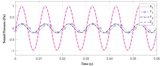
Assuming that the reflected signal is a pure sine wave with a certain delay, set the original vibration signal and the signal collected by its microphone as follows:
In Eq. (18), the time delay of adjacent signals relation is: . Performing phase shift on Eq. (18), the result is shown in Fig. 2. is the signal filtered the reflected noise out, and is very close to . It can be seen that the Phase-shifted algorithm can filter the reflected signal with pure sine wave delay.
Fig. 2Denoising reflection about pure sine wave
4.2. Composite wave of multiple sine waves
The reflections of multiple sine waves with different time delays are simulated and filtered. The original signal and the signal collected by microphone are as follows:
Phase shifting of Eq. (20) yields the results shown in Fig. 3. The Phase-shifted algorithm can denoise composite waves with different delays of the reflected signal.
Fig. 3Denoising reflection about multiple sine waves
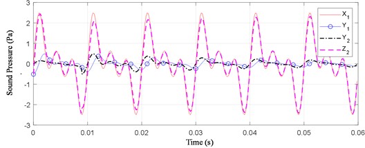
4.3. Composite wave of multiple sine waves with their attenuated waves
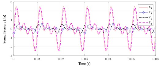
Further, the reflection with both amplitude and time decay of multiple sine waves is simulated and filtered, the original signal and its microphone-collected signal are listed here:
Phase shifting of Eq. (22) gives the results shown in Fig. 4. The Phase-shifted algorithm can filter out reflections with amplitude-attenuation characteristics and different time delays for each different frequency.
Fig. 4Denoising reflection about superposition of multiple sine waves and their attenuated waves
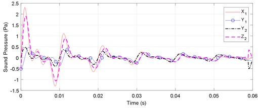
4.4. Composite wave of multiple transient waves with their attenuated waves
Further, the reflection with both amplitude and time decay of transient waves is simulated and filtered, the original signal and its microphone-collected signal are listed here:
Phase shifting of Eq. (24) gives the results shown in Fig. 5. The Phase-shifted algorithm can filter out reflections with amplitude-attenuation characteristics and different time delays for each different frequency.
Fig. 5Denoising reflection about superposition of multiple transient waves and their attenuated waves
5. Comparison with the conventional beamforming
Simulations of conventional beamforming and Phase-shifted beamforming algorithms are presented below to illustrate the latter’s superiority in identifying near-field sources with reflected noise. A non-equally spaced linear beamforming array of five microphones is constructed, where the fourth and fifth microphones are interfered with by the near-field reflected signal and the source is positioned between the fourth and fifth microphones. The array parameters are:
– Coordinates of vibration sources: P0 = (0.8, 0.21).
– Microphone coordinates: P1 = (0.1, 0.2), P2 = (0.15, 0.2), P3 = (0.3, 0.2), P4 = (0.8, 0.2), P5 = (1, 0.2).
Intervals in both the length and width directions of the beamforming array is [0, 1.25], and grid accuracy is 0.0125. Setting the signal sampling frequency to 10000 Hz, total signal length to 5000, the signal collected by each microphone is represented by the following equations:
where – original signal frequency, 100 Hz; – steering vector coefficient, ; – distance from the th microphone to the center of the array, with the coordinates of the center of array being (0.625, 0.625).
5.1. Tradition
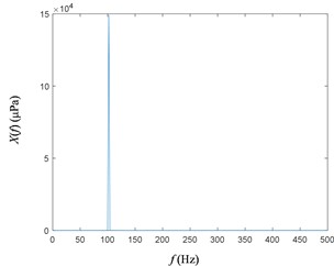
Due to the presence of the reflected signal, the FFT results for the 4th and 5th microphone signals are shown in Fig. 6. As is shown, the original signal subject to zero-frequency and double-frequency interference.
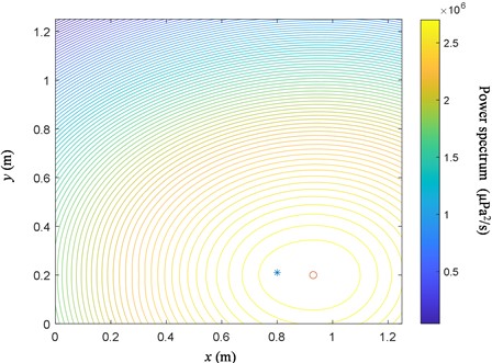
The source obtained using conventional beamforming is shown in Fig. 7. Large discrepancy between identified sources and real sources is due to the noise reflection. The source position locates at the “*” while the identified position at the “o”. (The coordinates of “o” are (0.875,0.2)), and the distance of difference between calculated result and actual vibration source is 0.0757.
Fig. 6Autospectrum of sound pressure signal with reflection
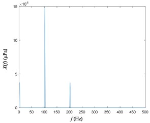
a) Autospectrum of the 4th microphone signal
b) Autospectrum of the 5th microphone signal
Fig. 7Simulation result for conventional beamforming
5.2. Phase shifting
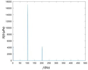
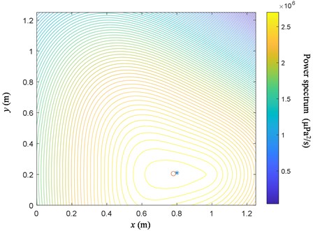
Set the segment interval to 6 fundamental frequency (100Hz) cycles, the FFT results of the 4th and 5th microphone signals after phase shifting are shown in Fig. 8. Phase-shifted algorithm successfully filters out reflective interference noise. The result of the beamforming using the phase-shifted signals from the microphone array is shown in Fig. 9. Phase-shifted beamforming algorithm can accurately locate the source by filtering out the reflected signals. Compared to Fig. 7, the Phase-shifted beamforming algorithm also obtains a more accurate source contour line, with a smaller contour ring (innermost ring) of the source and a distance difference of 0.0160 between the identification point and the source, which is much lower than the conventional method. It shows that the presented algorithm can more accurately locate the vibration faults of reflective structures, the identified position is 4.73 times more accurate than by the traditional beamforming method.
Fig. 8Autospectrum of sound pressure signal without reflection
a) Autospectrum of the 4th microphone signal
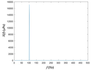
b) Autospectrum of the 5th microphone signal
Fig. 9Simulations of phase-shifted beamforming
6. Conclusions
In order to reduce reflection influence on near-field beamforming of the fault location about structure with acoustic reflective components, this paper proposes a phase-shifted beamforming algorithm based on signal segmentation and cross-correlation theory, and verifies the effectiveness of the method through simulations. The Phase-shifted beamforming location algorithm can effectively reduce interferences from pure sine wave, composite multiple sine waves, superposition of sine waves or transient waves and their attenuated waves, and other types of reflected noise in microphone raw data. By reducing the effect of reflected noise, the phase-shifted beamforming algorithm improves the accuracy of the CSM, allowing for more accurate localization of vibration faults.
References
-
P. Chiariotti, M. Martarelli, and P. Castellini, “Acoustic beamforming for noise source localization – Reviews, methodology and applications,” Mechanical Systems and Signal Processing, Vol. 120, No. 4, pp. 422–448, Apr. 2019, https://doi.org/10.1016/j.ymssp.2018.09.019
-
G. Huang, J. Benesty, and J. Chen, “Design of robust concentric circular differential microphone arrays,” The Journal of the Acoustical Society of America, Vol. 141, No. 5, pp. 3236–3249, May 2017, https://doi.org/10.1121/1.4983122
-
S. J. Lai and S. M. Li, “Noise source identification of rotating machinery based on near-field acoustic pressure arrays,” Noise and Vibration Control, Vol. 32, No. 3, pp. 122–126, 2016.
-
R. Merino-Martínez, M. Snellen, and D. G. Simons, “Functional beamforming applied to imaging of flyover noise on landing aircraft,” Journal of Aircraft, Vol. 53, No. 6, pp. 1830–1843, Nov. 2016, https://doi.org/10.2514/1.c033691
-
J. Hald, “Cross-spectral matrix diagonal reconstruction,” in Inter-Noise 2016 – 45th International Congress and Exposition on Noise Control Engineering: Towards a Quieter Future, pp. 5833–5844, 2016.
-
Q. Leclère, N. Totaro, C. Pézerat, F. Chevillotte, and P. Souchotte, “Extraction of the acoustic part of a turbulent boundary layer from wall pressure and vibration measurements,” in NOVEM 2015: Noise and Vibration – Emerging Technologies, pp. 13–15, 2015.
-
T. F. Brooks and W. M. Humphreys, “A deconvolution approach for the mapping of acoustic sources (DAMAS) determined from phased microphone arrays,” Journal of Sound and Vibration, Vol. 294, No. 4-5, pp. 856–879, Jul. 2006, https://doi.org/10.1016/j.jsv.2005.12.046
-
P. Sijtsma, “CLEAN based on spatial source coherence,” International Journal of Aeroacoustics, Vol. 6, No. 4, pp. 357–374, 2009.
-
P. Sijtsma, A. Dinsenmeyer, J. Antoni, and Q. Leclere, “Beamforming and other methods for denoising microphone array data,” Beamforming and other methods for denoising microphone array data, Vol. 2653, pp. 1–16, 2019, https://doi.org/10.48550/arxiv.1906.02965
-
I. Lopez Arteaga, R. Scholte, and H. Nijmeijer, “Improved source reconstruction in Fourier-based near-field acoustic holography applied to small apertures,” Mechanical Systems and Signal Processing, Vol. 32, No. 10, pp. 359–373, Oct. 2012, https://doi.org/10.1016/j.ymssp.2012.06.002
-
D. Stephens and D. Sree, “Tone and broadband noise separation from acoustic data of a scale-model counter-rotating open rotor,” 20th AIAA/CEAS Aeroacoustics Conference, Vol. 2744, pp. 1–11, Jun. 2014, https://doi.org/10.2514/6.2014-2744
-
D. Sree, “A Novel Signal Processing Technique for Separating Tonal and Broadband Noise Components from Counter-Rotating Open-Rotor Acoustic Data,” International Journal of Aeroacoustics, Vol. 12, No. 1-2, pp. 169–188, Jun. 2013, https://doi.org/10.1260/1475-472x.12.1-2.169
-
J. Prezelj, L. Čurović, T. Novaković, and J. Murovec, “A novel approach to localization of environmental noise sources: Sub-windowing for time domain beamforming,” Applied Acoustics, Vol. 195, No. 7, p. 108836, Jun. 2022, https://doi.org/10.1016/j.apacoust.2022.108836
-
I. Davis and G. J. Bennett, “Novel noise-source-identification technique combining acoustic modal analysis and a coherence-based noise-source-identification method,” AIAA, Vol. 53, No. 10, pp. 3088–3101, 2015.
-
N. Chu, A. Mohammad-Djafari, and J. Picheral, “Robust Bayesian super-resolution approach via sparsity enforcing a priori for near-field aeroacoustic source imaging,” Journal of Sound and Vibration, Vol. 332, No. 18, pp. 4369–4389, Sep. 2013, https://doi.org/10.1016/j.jsv.2013.02.037
-
J. Antoni, T. Le Magueresse, Q. Leclère, and P. Simard, “Sparse acoustical holography from iterated Bayesian focusing,” Journal of Sound and Vibration, Vol. 446, No. 28, pp. 289–325, Apr. 2019, https://doi.org/10.1016/j.jsv.2019.01.001
About this article

The research was supported by National Science and Technology Major Project (J2019-IV-0004-0071) and Basic Scientific Research Business Expenses of Central Universities (56XAA20064).
The datasets generated during and/or analyzed during the current study are available from the corresponding author on reasonable request.
The authors declare that they have no conflict of interest.
