Abstract
The instantaneous dynamic contact state analysis is carried out to reveal the process of scuffing failure of the gear tooth pair. A stick-slip dynamic model of a two-gear set is proposed and the coupling effects of time-varying mesh stiffness, tooth separations, friction between the gear teeth surfaces, and potential stick-slip are considered. Dynamic analysis shows that stick contact is an important source of tooth scuffing failure. Additionally, stick contact dramatically increases the vibration amplitudes and causes chaos. Parametric studies show that heavy load and rough tooth surfaces increase the probability of sticking and increase the time of stick state over a single mesh period. This study provides a design guard for avoiding scuffing failure and improving the reliability of gear transmission.
1. Introduction
Friction between mating teeth dramatically affects gear dynamics. On the one hand, friction is one of the vibration excitations in the off-line-of-action direction [1]. Friction increases the magnitude of dynamic transmission error (DTE) [2], weakens the reduction effect of tooth profile modifications on DTE [3], and significantly affects high-frequency parts at the low speed [4]. With increasing friction coefficients, the spectral amplitudes of the meshing components are increased [5]. On the other hand, friction suppresses the gear vibrations like damping [6] and acts as one of the main sources of power loss [7, 8]. The meshing force fluctuations, vibrations in the line-of-action [1], and the gear angular displacements [4], [9] are reduced by friction. Friction also reduces the large oscillations at certain resonant conditions [10] and causes impulses at the pitch points where the friction changes its direction [11]. Additionally, friction has some other effects on gear dynamics. Liu and Parker [12] found that different types of instabilities have different sensitivities to the friction moment and bending effect. The torsional response is probably less sensitive to tooth friction than the bending response [13]. The effect of friction during approach and recessing is converse on the time-varying mesh stiffness [14]. Another important potential hazard of gear tooth friction is the scuffing of gear teeth [8], [15-17]. Scuffing may damage the designed tooth profile and induce additional excitation of vibrations. In tooth surface fault diagnosis, the plate and beam models are usually used to approximate the gear body and gear tooth, respectively. And the dynamic characters of the plate [18-20] and the beam [21, 22] have been developed for a long time. The existing research on gear bonding failure is mainly through oil analysis [23] and fatigue tests [24]. However, few studies have analyzed the adhesive failure of gears through dynamics. Dynamic analysis can go deeper into the instantaneous state of tooth surface contact and analyze the process of tooth surface bonding from a more accurate dimension.
The interactions between friction and other factors make the nonlinear vibration of the gear more complicated [4]. For helical gear sets, the effect of friction on teeth contact stress varies at different contact positions, which induces nonlinearity [25]. For herringbone gear sets, the effects of friction may be covered by the effects of profile errors [1]. Due to the interaction of the mesh force and friction force, tooth profile modification may even amplify the motions in the off-line-of-action [2]. The dissipation mechanism of tooth friction is also substantially influenced by tooth profile modifications [7].
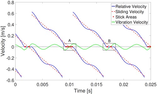
Fig. 1Effects of vibration velocity on sliding velocity
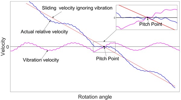
The stick-slip phenomenon, which is caused by friction, may lead to negative damping that can cause self-excited oscillations of mechanical structures in certain instances [26]. Under the effects of the wheel-set stick-slip, the gear transmission system of high-speed trains has a larger superharmonic response and loses its stability because of Hopf bifurcation [27]. A prominent characteristic of gear tooth friction is the reversal of its direction near the pitch point. Repeatedly changing of the friction direction induces significant oscillatory bearing forces [28]. Usually, the contributions of the vibration velocity to the actual relative sliding velocity are ignored. Under this approximate treatment, as shown in Fig. 1, the relative sliding velocity between the mating gear teeth is monotonic as the gear rotates, and the direction of the relative sliding velocity reverses when the contact line exactly passes through the pitch point. However, the vibration velocity induces fluctuations in the relative sliding velocity, and the direction-reversing point is not exactly at the pitch point. Furthermore, there even exists more than one direction-reversing point near the pitch point, as shown in the magnified figure of Fig. 1. The repeated changes of the sliding velocity direction mean the repeated reversals of the friction direction. In the areas of the magnified figure of Fig. 1, the value of the sliding velocity is close to zero, and the two gear tooth surfaces seem to bond together. It's not clear whether the sticking phenomenon exists in this area. Furthermore, the effects of the sticking phenomenon on the dynamic character of the gear transmission are also still not clear.
In this study, the gear dynamics with the effects of the stick-slip phenomenon are studied. A stick-slip dynamic model of a two-gear set is proposed. In this model, time-varying mesh stiffness, tooth separation, gear teeth friction, and the potential stick-slip phenomenon are considered. Considering the contributions of the vibration velocity to the gear teeth sliding velocity, transition conditions between the stick and slip states are revealed. Discussions of the dynamic response of gear transmissions under the stick-slip effect offer a comprehensive understanding of gear scuffing from a dynamic perspective. The remainder of the paper is organized as follows. In the next section, the modeling details and the governing equations of motion for a two-gear set with stick-slip are presented. The effects of stick-slip on the dynamic responses and parametric study are discussed in Section 3. Concluding remarks are given in the last section.
2. Stick-model and slip-model
In this section, a stick-slip dynamic model of a two-gear set is proposed. In this model, time-varying mesh stiffness, tooth separation, friction between the mating gear teeth, and the potential stick-slip phenomenon are considered. This stick-slip dynamic model is the combination of a stick model and a slip model. The slip model in this current study is the traditional 6 degrees of freedom (DOF) model considering two translational and rotational motions. The stick model is an evolution of the slip model based on instantaneous dynamic conditions.
2.1. Slip-model
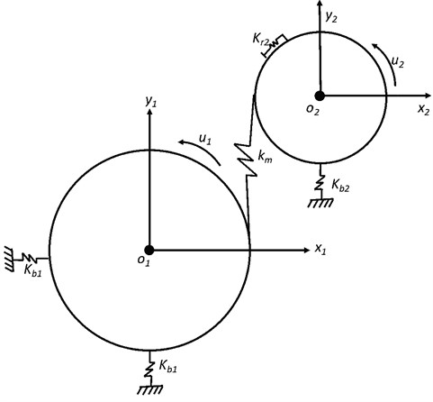
Fig. 2 shows the traditional slip model with 6 DOF. In this model, two translational motions and the rotational motion of each gear are considered. The components are modeled as rigid bodies and the masses are concentrated in the corresponding centroid. A linear spring is used to model the compliance of gear mesh. In Fig. 2, and represent the translational support stiffness, is the rotational stiffness, and is the mesh stiffness. and denote the translational motions. denotes the rotational motions, and counterclockwise is positive.
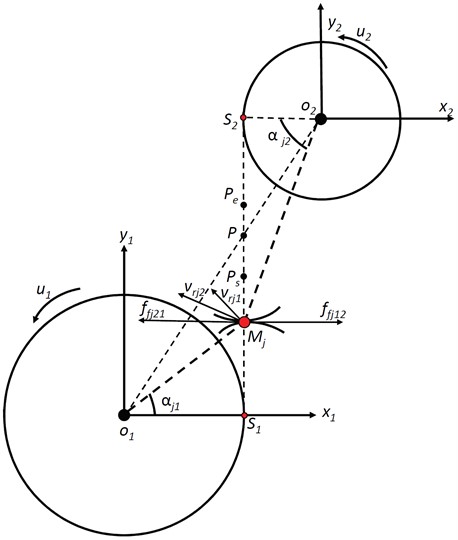
As shown in Fig. 3, is the mesh line and point is the pitch point. represents the moving contact point between the th mating gear teeth. For spur gears, 1 and 2. and are the velocities of the mesh teeth at mesh point , respectively. The direction of is perpendicular to line , and the direction of is perpendicular to line . The components of and on the -axis are equal during the whole mesh process; and are the pressure angles of the driving gear and driven gear, respectively. represents the friction forces, whose direction is perpendicular to line . The sliding friction is positive when it is directed to the left, and is positive when it is directed to the right.
Fig. 2Slip model of two-gear set
Under the running state, the gear teeth start to contact near , and moves towards . Suppose there is no reversal of the friction direction before arrives at point and also no reversal after passes by point . When moves in , the components of on the -axis are larger than those of . The direction of the friction force applied on the 1st gear tooth is to the left. In addition, the reaction force points to the right. After passes by point , points to the right, and points to the left. When is in , the friction oscillates, and the mating teeth may transit between the slip and stick states. The motion equations of the gear pair under the slip state could be expressed as Eq. (1) and Eq. (2):
where represents mass, represents damping and represents the moment of inertia. and are respectively the base radii of the gears. is the transmitted torque applied on the driving gear. represents the contact ratio and is the compressive defections of the gear mesh:
Fig. 3Relative sliding velocity
The matrix form of Eq. (1) and (2) could be expressed as:
where is the mass matrix, and is the support stiffness matrix:
is the time-varying mesh stiffness matrix, as expressed in Eq. (6). in Eq. (7) is the time-varying mesh stiffness. is the tooth separation function, as expressed in Eq. (8):
and are respectively the friction force vector and applied torque vector, as expressed in Eq. (9) and (10):
The sliding friction force could be expressed as:
where is the relative sliding velocity between the th gear mesh, as expressed in Eq. (12):
where and are the rotational speed.
2.2. Stick-model
As shown in Fig. 1, there may exist more than one direction reversal of friction when the moving point is near the pitch point. At the direction-changing point, if the force that attempts to slide one tooth surface over the other is less than the maximum possible friction force, the surfaces of the meshing gear teeth stick together. The preconditions for stick condition is:
where and are the force attempting to slide one tooth surface over the other, which can be obtained by the instantaneous conditions. And is the mesh force of the mating gear teeth:
To simplify the equations, let:
Substituting Eq. (17) to Eq. (14), the relationship of and is obtained:
Respectively integrating and differentiating Eq. (18), there exists:
Substituting Eq. (19) to Eq. (1) and Eq. (2), the equations of the system motions degenerate as Eq. (20) and (21):
Comparing the motion equations of the slip model and stick model, one can find that the stick model has one FOD less than the slip model. That is because has a certain relationship with under the stick state, and is eliminated. These stick-model equations could be expressed in matrix forms as:
where the subscript denotes the matrices and vectors in stick-model:
The gear set is in stick state or slip state depending on Eq. (14). If both conditions in Eq. (14) are satisfied, the gear set is in the stick state. Otherwise, the slip state domains the gear set. In the process of numerical integration, a status check based on Eq. (14) is required at each substep calculation.
3. Results and discussions
In this chapter, an example gear set is applied to eliminate the effects of stick-slip on the dynamic responses. The main parameters are shown in Tabel 1. Unlike frictionless gear models, constant input and output torques cannot be assumed since energy dissipation due to tooth friction [13].
Table 1Main parameters of an example gear train
Gear1 | Gear2 | |
Mass (kg) | 17.29 | 101.62 |
Inertia (kgm2) | 0.139 | 4.799 |
Tooth number | 33 | 80 |
Tooth width (mm) | 200 | 200 |
Translational stiffness (N/m) | 4.06e7 | 4.11e10 |
Damping ratio | 0.02 | |
Pressure angle (deg) | 20 | |
Coefficient of friction | 0.02 | |
Module (mm) | 6 | |
Mean Mesh stiffness (N/m) | 4.05e9 | |
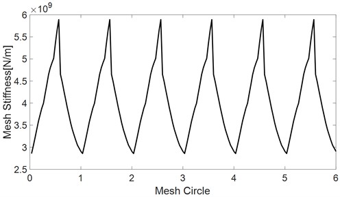
The mesh stiffness of the example gear train is obtained by the Finite element quasi-static analysis, as shown in Fig. 4.
Fig. 4Mesh stiffness of the example gear train
3.1. Comparisons of modal properties
Fig. 5 and Fig. 6 show the comparisons of modal shapes and natural frequencies of the slip model and stick model.
Fig. 5Modal shapes and natural frequencies of slip model
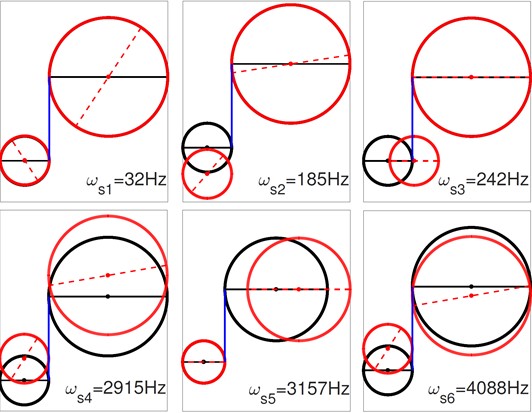
As shown in Fig. 5, the first natural frequency of the slip model is 32 Hz, which is associated with the ‘rigid’ mode. The rigid mode has pure rotational motions of both gears. The 3rd and 5th modes have pure translational motions of Gear1 and Gear2, respectively. The 2nd, 4th and 6th modes have combined motions of the translation and rotation.
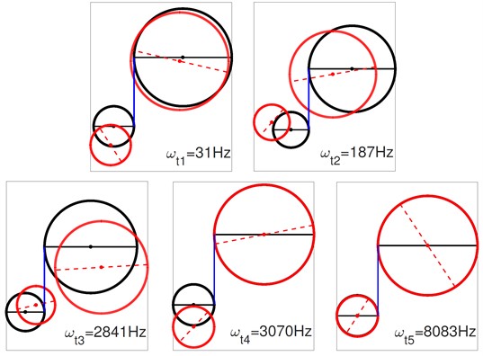
The first natural frequency of the stick model, as shown in Fig. 6, is approximately equal to the first natural frequency of the slip model. However, these two modes are very different in their corresponding modal shapes. There are similar differences between the second mode, and between the 4th mode of the slip model and the 3rd mode of the stick model. In the stick state, these two gears are bonded in the direction. Therefore, there are no relative displacements between and in any of the modal shapes of the stick model. And, in the stick model, there is no corresponding mode to the 3rd and 5th modes of the slip model. The results of modal analysis, reveal that the stick effect has a dramatic influence on both natural frequencies and modal shapes.
Fig. 6Modal shapes and natural frequencies of stick model
3.2. Comparisons of the dynamic responses
Once the stick occurs, the vibration conditions of the gear set vary between the stick state and the slip state. The constant transitions between these states certainly induce impacts. The calculation process of dynamic response is shown in the flow chart in Fig. 7.
Fig. 7Flow chart of the calculation process
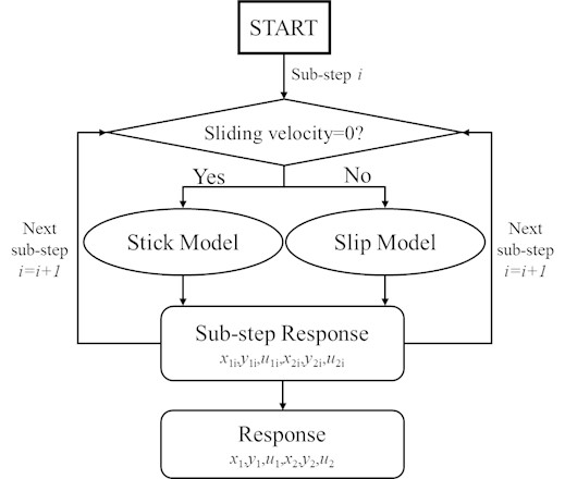
Fig. 8 and Fig. 9 show the comparisons of the velocities of the slip model and stick-slip model. From Fig. 8, one can see that the relative velocity is close to zero and that there exists a small fluctuation near the pitch point. The relative velocity changes its direction several times near the pitch point, as shown in the amplified inset in Fig. 8. These repeated changes in the direction of the relative velocity are also reflected in the friction direction, as shown in Fig. 12.
Fig. 8Velocities of slip model
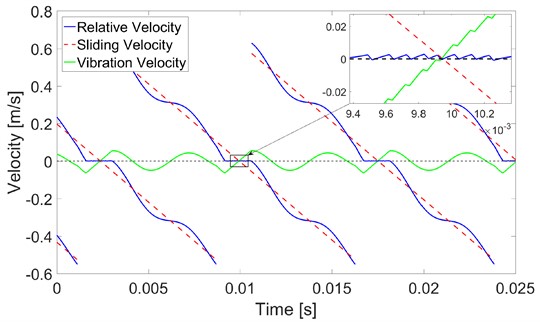
Fig. 9(a) shows the corresponding velocities of the stick-slip model. The solid points denote the stick state. Stick occurs in every single mesh period. However, the stick situation in any specific mesh period is different from that in its adjacent mesh periods. The specific situation is the same as that in every other mesh period. Fig. 9(b) and (c) show the details in rectangles A and B of Fig. 9(a), respectively. Stick occurs four times in the single mesh period marked A. And under the stick state, the vibration velocity is opposite to the sliding velocity with equal value. Therefore, the relative velocity exactly equals zero. Stick occurs twice in the single mesh period marked B, and the relative velocity changes its direction rapidly out of the scope of the stick. These repeated changes in the directions of relative velocity are also reflected in the friction direction shown in Fig. 13.
Fig. 9Velocities of stick-slip model
a)
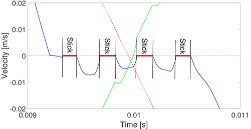
b)
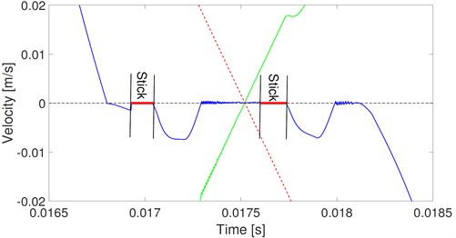
c)
Fig. 10Mesh force of slip model
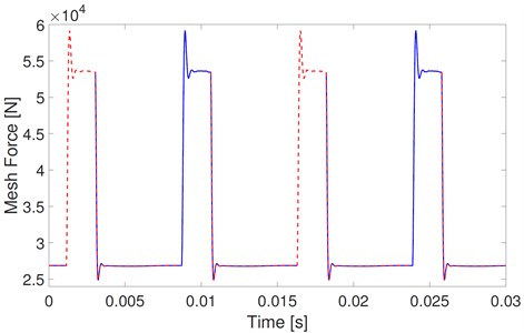
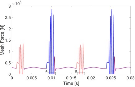
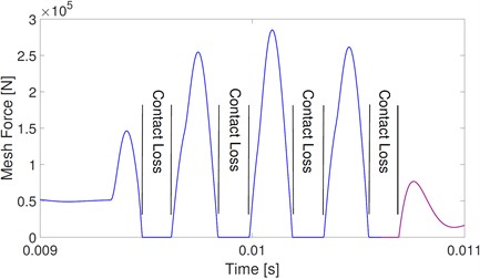
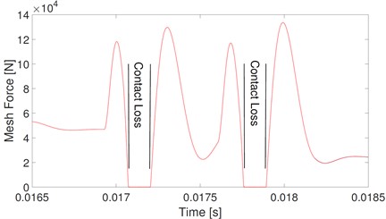
Fig. 11Mesh force of the stick-slip model
a)
b)
c)
The corresponding mesh forces of the slip model and stick-slip model are shown in Fig. 10 and Fig. 11. In Fig. 10, mesh forces fluctuate from 25 kN to 60 kN. These fluctuations are mainly caused by the varying mating mesh tooth number, and the mesh force fluctuations are the same among all mesh periods. However, as shown in Fig. 11(a), the mesh force fluctuations of the stick-slip model are the same every other mesh period, and the mesh forces between adjacent mesh periods are much different. In the mesh period marked A, mesh forces fluctuate from 0 to 280 kN. The mesh forces fluctuate from 0 to 140 kN in the mesh period marked B. Contact loss occurs when mesh force equals 0. Details on mesh forces in rectangles A and B of Fig. 11(a) are shown in Fig. 11(b) and (c), respectively. Similar to the stick effect, contact loss occurs four times in mesh period A and twice in mesh period B. Comparisons of the mesh forces of slip and stick-slip models show that the excitation effect of stick causes contact loss, and the interactions of stick and contact loss dramatically increase the fluctuations of mesh forces.
As shown in Fig. 8, in the slip model, the relative velocity changes its direction frequently near the pitch point, causing frequent direction changes of the corresponding friction. Over the whole period, friction always consists of sliding friction. The mating teeth are not always able to break through the frictional resistance at every direction-changing point. The state between the mating teeth depends on whether the instantaneous state satisfies Eq. (14). The mating gear teeth are bonded together once Eq. (14) is satisfied, and friction should be recognized as static friction.
Fig. 12Friction of slip model
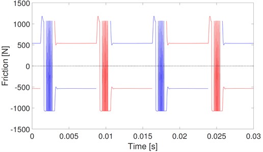
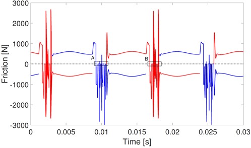
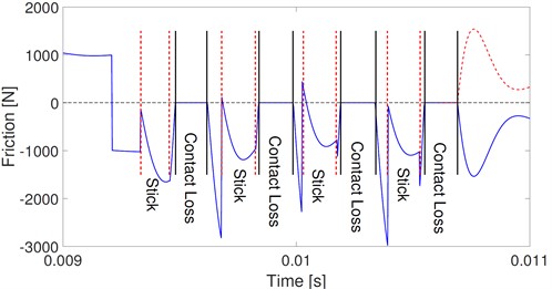
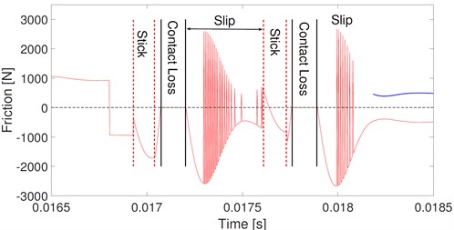
Fig. 13(a) shows the corresponding friction of the stick-slip model. Similar to the mesh force, fluctuations in friction are dramatically increased by the stick. The frictions in the adjacent mesh periods are much different. Details of periods A and B in Fig. 13(a) are shown in Fig. 13(b) and (c), respectively. In period A, stick and contact loss occur alternatively, and there exists a short slip between stick and contact loss. The interaction of stick, slip, and contact loss leads to a much more complex dynamic friction. There are four and two transitions among these three states in periods A and B, respectively. Under the stick state, the mating teeth are bonded together and friction equals the force that tries to pull them out. Under the slip state, the mating teeth slide one from another, and friction is recognized as sliding friction. As shown in Fig. 13(c), the direction of friction under the slip state changes frequently as the direction of relative velocity changes. Under the contact loss state, the mating teeth lose their contact, and no mesh force or friction between them.
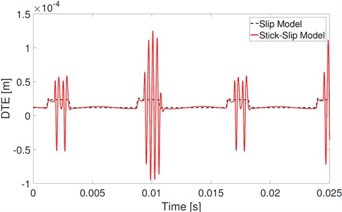
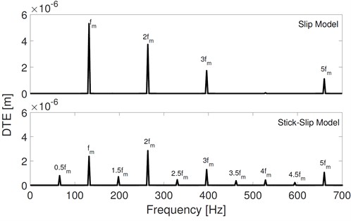
Finally, comparisons of DTE are shown in Fig. 14. Under the alternative effects of the stick, slip, and contact loss, the fluctuation of DTE obtained by the stick-slip model is much larger than that obtained by the slip model. The DTE obtained by stick-slip has much more half frequency components of mesh frequency. While the amplitudes of , 2, and 3 of DTE obtained by the stick-slip model are slightly lower than that obtained by the slip model. It means that part of the dynamic energy is transmitted from the multiple components to half components of mesh frequency.
Fig. 13Friction of stick-slip model
a)
b)
c)
Fig. 14Comparisons of DTE of slip and stick-slip model
a)
b)
3.3. Effects of working conditions on the stick states
In this section, the effects of key parameters, including rotation speed, friction coefficient, and applied torque on the occurrence of the stick are discussed. We define two parameters to illustrate the degree of stick and contact loss. The intercept for a sufficiently long time in steady-state vibration, which is denoted by . The stick ratio is defined as the ratio of the stick time in this intercepted period to . The contact loss ratio is the ratio of the corresponding contact loss time to :
Fig. 15 shows the effects of the rotation speed on the stick ratio and contact loss ratio. For the example gear set in this study, the stick occurs only when the rotation speed is in the low ranges on [0, 300] r/min. Stick occurs in three single ranges in the scope of [0, 300] r/min, and the trend of the contact loss ratio versus rotation speed is similar to that of the stick ratio. However, there is no certain relation between the stick ratio and rotation speed.
Fig. 15Stick-ratio and contact-ratio versus rotate speed
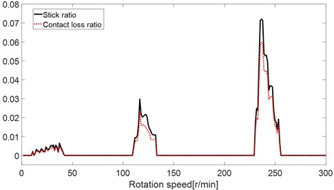
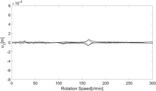
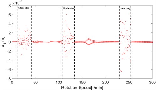
Fig. 16 shows the bifurcation diagrams with varying rotation speeds. Without considering the stick phenomenon, as shown by the bifurcation diagrams of the slip model in Fig. 16(a), the dynamic response is steady and periodical. However, the dynamic response is chaotic in the ranges with the stick effect, as shown by the bifurcation diagrams of the stick-slip model in Fig. 16(b). The dynamic response obtained by the stick-slip model out of the stick ranges almost equals that obtained by the slip model.
Fig. 16Bifurcation diagrams of slip and stick-slip models
a)
b)
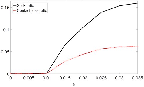
The friction coefficient is another key parameter, and Fig. 17 shows the effects of on the stick ratio and the contact loss ratio. In the range of [0; 0:01], the stick ratio and the contact loss ratio remain at 0. As increases above 0.01, the stick ratio monotonically increases. The trend of the contact loss ratio is similar to that of the stick ratio.
Fig. 17Stick-ratio and contact-ratio versus friction coefficient
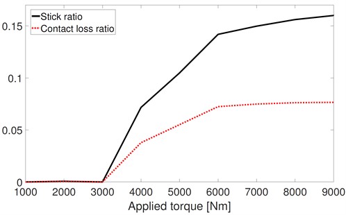
The applied torque has similar effects to those of the friction coefficient on the stick ratio and the contact loss ratio, as shown in Fig. 18. When the applied torque is in the range of [0, 3000] Nm, the stick ratio and the contact loss ratio remain almost at 0. As the applied torque increases above 3000 Nm, the stick ratio monotonically increases. And the trend of the contact loss ratio is similar to that of the stick ratio.
Based on these parametric studies, designers should avoid choosing parameters in the designing process that may later result in the stick.
Fig. 18Stick-ratio and contact ratio versus applied torque
4. Conclusions
In this paper, the instantaneous dynamic contact state analysis is carried out to reveal the process of scuffing failure of the gear tooth pair. A stick-slip dynamic model of a two-gear set is proposed, and the coupling effects of time-varying mesh stiffness, tooth separation, friction, and the potential stick-slip phenomenon are considered. An example gear set is applied and the results of numerical integration show that the sticking phenomenon has a dramatic effect on gear dynamics. This study provides a design guard for avoiding scuffing failure and improving the reliability of gear transmission, and several conclusions are obtained.
1) Stick-slip dynamic model can capture the transition of the contact states between the stick and slip of the gear tooth pair. The instantaneous dynamic contact state analysis offers a comprehensive understanding of gear scuffing from a dynamic perspective.
2) The stick phenomenon has dramatic effects on gear dynamics. The mating gear teeth are bonded together once the stick occurs, and the modal shapes are dramatically changed. The stick phenomenon involves excitation and induces considerable fluctuation in the DTE, mesh forces, and friction. Stick causes contact loss, and the interaction effects of stick and contact loss lead to much more complex than the nonlinearity gear dynamics. Under the effects of the stick, there exists more than one contact loss in a mesh period, which is different from the assumption in previous studies.
3) Stick occurs only at low rotation speed ranges. Stick causes the gear dynamic response chaotic. Out of the stick speed ranges, the dynamic response is periodical, similar to that obtained by the slip model. Stick is more likely to occur under heavy load and poor lubrication conditions. The stick ratio increases with increasing applied torque and with increasing friction coefficient. The contact loss ratio has similar growth trends to the stick ratio.
References
-
C. Liu, D. Qin, and Y. Liao, “Dynamic model of variable speed process for herringbone gears including friction calculated by variable friction coefficient,” Journal of Mechanical Design, Vol. 136, No. 4, Apr. 2014, https://doi.org/10.1115/1.4026572
-
S. He, R. Gunda, and R. Singh, “Effect of sliding friction on the dynamics of spur gear pair with realistic time-varying stiffness,” Journal of Sound and Vibration, Vol. 301, No. 3-5, pp. 927–949, Apr. 2007, https://doi.org/10.1016/j.jsv.2006.10.043
-
O. Lundvall, N. Strömberg, and A. Klarbring, “A flexible multi-body approach for frictional contact in spur gears,” Journal of Sound and Vibration, Vol. 278, No. 3, pp. 479–499, Dec. 2004, https://doi.org/10.1016/j.jsv.2003.10.057
-
C. Siyu, T. Jinyuan, L. Caiwang, and W. Qibo, “Nonlinear dynamic characteristics of geared rotor bearing systems with dynamic backlash and friction,” Mechanism and Machine Theory, Vol. 46, No. 4, pp. 466–478, Apr. 2011, https://doi.org/10.1016/j.mechmachtheory.2010.11.016
-
L. Jiang, Z. Deng, F. Gu, A. D. Ball, and X. Li, “Effect of friction coefficients on the dynamic response of gear systems,” Frontiers of Mechanical Engineering, Vol. 12, No. 3, pp. 397–405, Sep. 2017, https://doi.org/10.1007/s11465-017-0415-4
-
H. Jiang, Y. Shao, and C. K. Mechefske, “Dynamic characteristics of helical gears under sliding friction with spalling defect,” Engineering Failure Analysis, Vol. 39, pp. 92–107, Apr. 2014, https://doi.org/10.1016/j.engfailanal.2014.01.008
-
Y. Diab, F. Ville, and P. Velex, “Investigations on power losses in high-speed gears,” Proceedings of the Institution of Mechanical Engineers, Part J: Journal of Engineering Tribology, Vol. 220, No. 3, pp. 191–198, Mar. 2006, https://doi.org/10.1243/13506501jet136
-
J.-H. Xue, W. Li, and C. Qin, “The scuffing load capacity of involute spur gear systems based on dynamic loads and transient thermal elastohydrodynamic lubrication,” Tribology International, Vol. 79, pp. 74–83, Nov. 2014, https://doi.org/10.1016/j.triboint.2014.05.024
-
A. Guerine, A. El Hami, L. Walha, T. Fakhfakh, and M. Haddar, “A polynomial chaos method for the analysis of the dynamic behavior of uncertain gear friction system,” European Journal of Mechanics – A/Solids, Vol. 59, pp. 76–84, Sep. 2016, https://doi.org/10.1016/j.euromechsol.2016.03.007
-
M. Vaishya and R. Singh, “Sliding friction-induced non-linearity and parametric effects in gear dynamics,” Journal of Sound and Vibration, Vol. 248, No. 4, pp. 671–694, Dec. 2001, https://doi.org/10.1006/jsvi.2001.3818
-
Z. Yang, J.-Z. Shang, and Z.-R. Luo, “Effect analysis of friction and damping on anti-backlash gear based on dynamics model with time-varying mesh stiffness,” Journal of Central South University, Vol. 20, No. 12, pp. 3461–3470, Dec. 2013, https://doi.org/10.1007/s11771-013-1870-7
-
G. Liu and R. G. Parker, “Impact of tooth friction and its bending effect on gear dynamics,” Journal of Sound and Vibration, Vol. 320, No. 4-5, pp. 1039–1063, Mar. 2009, https://doi.org/10.1016/j.jsv.2008.08.021
-
P. Velex and P. Sainsot, “An analytical study of tooth friction excitations in errorless spur and helical gears,” Mechanism and Machine Theory, Vol. 37, No. 7, pp. 641–658, Jul. 2002, https://doi.org/10.1016/s0094-114x(02)00015-0
-
A. Saxena, A. Parey, and M. Chouksey, “Effect of shaft misalignment and friction force on time varying mesh stiffness of spur gear pair,” Engineering Failure Analysis, Vol. 49, pp. 79–91, Mar. 2015, https://doi.org/10.1016/j.engfailanal.2014.12.020
-
R. Martins, R. Amaro, and J. Seabra, “Influence of low friction coatings on the scuffing load capacity and efficiency of gears,” Tribology International, Vol. 41, No. 4, pp. 234–243, Apr. 2008, https://doi.org/10.1016/j.triboint.2007.05.008
-
W. Tuszynski, R. Michalczewski, M. Szczerek, and M. Kalbarczyk, “A new scuffing shock test method for the determination of the resistance to scuffing of coated gears,” Archives of Civil and Mechanical Engineering, Vol. 12, No. 4, pp. 436–445, Dec. 2012, https://doi.org/10.1016/j.acme.2012.08.003
-
M. Savolainen and A. Lehtovaara, “An experimental investigation of scuffing initiation due to axial displacement in a rolling/sliding contact,” Tribology International, Vol. 119, pp. 688–697, Mar. 2018, https://doi.org/10.1016/j.triboint.2017.12.007
-
S. P. Parida and P. C. Jena, “Free and forced vibration analysis of flyash/graphene filled laminated composite plates using higher order shear deformation theory,” Proceedings of the Institution of Mechanical Engineers, Part C: Journal of Mechanical Engineering Science, Vol. 236, No. 9, pp. 4648–4659, May 2022, https://doi.org/10.1177/09544062211053181
-
S. P. Parida and P. C. Jena, “Advances of the shear deformation theory for analyzing the dynamics of laminated composite plates: an overview,” Mechanics of Composite Materials, Vol. 56, No. 4, pp. 455–484, Sep. 2020, https://doi.org/10.1007/s11029-020-09896-0
-
S. P. Parida and P. C. Jena, “Selective layer-by-layer fillering and its effect on the dynamic response of laminated composite plates using higher-order theory,” Journal of Vibration and Control, p. 107754632210811, Apr. 2022, https://doi.org/10.1177/10775463221081180
-
P. C. Jena, D. R. Parhi, and G. Pohit, “Dynamic investigation of FRP cracked beam using neural network technique,” Journal of Vibration Engineering and Technologies, Vol. 7, No. 6, pp. 647–661, Dec. 2019, https://doi.org/10.1007/s42417-019-00158-5
-
P. Charan Jena, “Identification of crack in SiC composite polymer beam using vibration signature,” Materials Today: Proceedings, Vol. 5, No. 9, pp. 19693–19702, 2018, https://doi.org/10.1016/j.matpr.2018.06.331
-
W. Tuszynski, R. Michalczewski, W. Piekoszewski, and M. Szczerek, “Effect of ageing automotive gear oils on scuffing and pitting,” Tribology International, Vol. 41, No. 9-10, pp. 875–888, Sep. 2008, https://doi.org/10.1016/j.triboint.2007.12.010
-
M. P. Proctor, F. B. Oswald, and T. L. Krants, “Shuttle rudder/speed brake power drive unit (PDU) gear scuffing tests with flight gears,” NASA Technical Reports 20060004794, 2005.
-
S. S. Patil, S. Karuppanan, I. Atanasovska, and A. A. Wahab, “Contact stress analysis of helical gear pairs, including frictional coefficients,” International Journal of Mechanical Sciences, Vol. 85, pp. 205–211, Aug. 2014, https://doi.org/10.1016/j.ijmecsci.2014.05.013
-
X. Liu, N. Vlajic, X. Long, G. Meng, and B. Balachandran, “Nonlinear motions of a flexible rotor with a drill bit: stick-slip and delay effects,” Nonlinear Dynamics, Vol. 72, No. 1-2, pp. 61–77, Apr. 2013, https://doi.org/10.1007/s11071-012-0690-x
-
G.-H. Huang, S.-S. Xu, W.-H. Zhang, and C.-J. Yang, “Super-harmonic resonance of gear transmission system under stick-slip vibration in high-speed train,” Journal of Central South University, Vol. 24, No. 3, pp. 726–735, Mar. 2017, https://doi.org/10.1007/s11771-017-3474-0
-
P. Velex and V. Cahouet, “Experimental and numerical investigations on the influence of tooth friction in spur and helical gear dynamics,” ASME 2000 International Design Engineering Technical Conferences and Computers and Information in Engineering Conference, Vol. 122, No. 4, pp. 515–522, Sep. 2000, https://doi.org/10.1115/detc2000/ptg-14430
About this article

The authors gratefully acknowledge the support by the Scientific Research Fund of high-level talents in Nanjing Institute of Technology (YKJ 201951) and the National Youth Foundation of China (52105191).
The datasets generated during and/or analyzed during the current study are available from the corresponding author on reasonable request.
Chao Xun established and proposed the model of this paper, and carried out the theoretical analysis. He Dai verified the accuracy of the model and revised the calculation results. Yunlong Wang proposed a revision to the model and proofread the manuscript.
The authors declare that they have no conflict of interest.
