Abstract
Blasting mining in open-pit has a significant impact on the adjacent slope, which often causes the rock mass cracking and spalling of the slope to form a landslide disaster. In order to explore the impact of blasting vibration on the adjacent slope, field tests were carried out with professional testing equipment, and several blasting vibration data were measured. Sadovsky formula was used for fitting analysis, and the influence coefficient of blasting vibration was obtained. The slope stability analysis was carried out by using the limit equilibrium SLIDE analysis software, and the slope safety factor under the influence of blasting vibration was obtained. The results show that: The maximum blasting vibration speed monitored in this blasting is 2.1987 cm/s, and the main vibration frequency is 14.6484 Hz. Therefore, according to the standards in the regulations, the impact of this blasting on the slope meets the corresponding requirements. In this slope stability analysis, the blasting vibration influence coefficient 0.032, when 40 m away from the final slope is used. Morgen Prince method and Spencer method generally have higher safety factors than Bishop method. The safety factor of the analysis section at the 45° slope angle is 1.217. The slope can maintain stability under the influence of blasting vibration.
Highlights
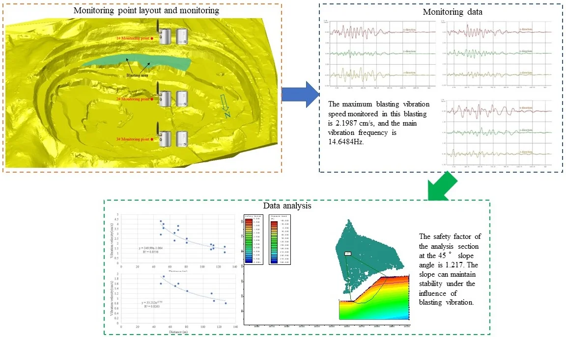
- The maximum blasting vibration speed monitored in this blasting is 2.1987 cm/s, and the main vibration frequency is 14.6484Hz.
- according to the standards in the regulations, the impact of this blasting on the slope meets the corresponding requirements. In this slope stability analysis, the blasting vibration influence coefficient Kc = 0.032, when 40 m away from the final slope is used.
- Morgen Prince method and Spencer method generally have higher safety factors than Bishop method. The safety factor of the analysis section at the 45° slope angle is 1.217. The slope can maintain stability under the influence of blasting vibration.
1. Introduction
Because most of the ore bodies and surrounding rocks of metal and non-metal mines are hard rocks, most open-pit mines mine ore bodies by blasting [1]-[3]. Shock wave will be produced during explosion, which is mainly caused by the propagation of pressure in the surrounding medium. After detonating the explosive, gas with high temperature and high pressure characteristics will be formed. This part of gas will exert compression disturbance on the surrounding medium, and the whole disturbance process is very strong, which will cause compression wave. As the gas expands, it will become mechanical energy, and the formed detonation wave will spread in all directions [4]-[6]. Obviously, the blasting vibration produced by blasting will have an adverse impact on the slope of open pit [7]-[10]. Therefore, it is urgent to carry out research on the impact of blasting vibration on the stability of stope slope in order to better guide the safety production of mining enterprises.
For the impact of blasting vibration on rock mass stability of slope, the relevant research work was carried outby many scholars [11]-[15]. For example, Taking the spandrel groove slope on the left bank of Baihetan Hydropower Station as an example, Dai et al. [16] investigated the displacement behavior of jointed rock slope, and studied the mechanism and influencing factors of displacement mutation caused by blasting excavation by FLAC3D program. Based on extensive parameter research, Zheng et al. [17] proposed the thickness weighting factor ft of explosion damage zone to quantify the influence of blast damage zone thickness on the evaluation of a given slope safety factor (FOS). Based on blast damage zone thickness weighting factor and the existing stability map, a stability model is proposed to estimate the FOS of slopes with different slope geometry and rock mass properties. Taking Daye Iron Mine as an example, Jiang et al. [18] established a three-dimensional numerical model of underground mining in open-pit mine, and studied the influence of underground mining activities on the blasting vibration attenuation of open-pit slope. The influence of blasting vibration on the open-pit slope of underground mining is also discussed. Taking GOL-E-GOHAR iron mine as a research case, Azizabadi et al [19] used waveform superposition to measure the vibration of single hole blasting and simulated the production blasting seismogram. The simulated production blasting seismogram was used as input, and the particle velocity time history of shaft wall blasting vibration was predicted by universal discrete element software (UDEC). From the influence of blasting vibration on slope stability carried out by many scholars above, it can be seen that blasting is an important factor leading to slope landslides and collapses. It is necessary to study the influence of blasting on slope stability in open-pit mines that mine ore bodies by blasting.
Based on the specific field blasting test, the blasting influence coefficient analysis is carried out, and the slope safety coefficient is obtained by using the limit equilibrium analysis method. Finally, the influence of blasting vibration on slope stability is determined.
In the process of rock blasting, the energy of detonation wave produced by explosive explosion gradually attenuates with the increase of propagation distance. The shock wave is transformed into stress wave and seismic wave. Because there are a large number of discontinuities in natural rock mass, which intensifies the reflection and refraction of seismic waves, it must greatly hinder the propagation of seismic waves and make their energy decay rapidly. Therefore, carrying out on-site blasting seismic wave testing and studying the propagation and attenuation law of blasting seismic wave in rock mass can not only guide the mining party to reasonably adopt blasting parameters and protect the safety of mine slope, but also use the measured blasting parameters for stability calculation, which are the two main purposes of on-site measured blasting vibration.
2. Engineering example
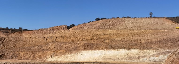
The high rocky slope of the open-pit mine is composed of multiple steps, with an overall slope angle of 45° and a slope height of 167 m. The slope angle of Quaternary soil and completely weathered layer is taken as 30-34°. The height of the step is 12 m, and the height of the end step is 24 m, which is the combination of two steps. The slope angle of the end step is 60°. The width of safety platform is 4-8 m. The width of cleaning platform is 8-16 m. The slope is shown in Fig. 1.
Fig. 1High rocky slope
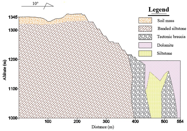
The lithology of the slope is mainly carbonaceous dolomite, silicified dolomite, dolomitic shale and dolomitic siltstone. The geological conditions of the slope are poor, and the rock on the slope surface is highly broken and seriously weathered. Faults, joints and fissures are relatively developed, and they are very easy to collapse under the influence of blasting vibration and rainfall. The geological profile of the slope is shown in Fig. 2.
Considering the internal and external factors of the slope, the safety risk of the slope is high. Previously, a large range of collapse occurred on the slope, and a small range of collapse and landslide also occurred in other locations. At the same time, there are also obvious cracks caused by blasting vibration. As a result, the step slope and safety platform cannot be implemented according to the design parameters, and obvious merging has occurred in some areas.
Fig. 2Geological profile of the rocky slope
At 3.27 km to the southeast of the slope, the terrain is relatively low, which is the confluence of surface streams in the nearby river valley. This point is more than 30 m to the south, and the stream is cut off, with a topographic elevation of 1337 m. There is a large reservoir about 1km away from the northeast of the slope, with an area of 0.1 km2. At the junction of the lower part of the reservoir spillway and the riverbed, the topographic elevation is 1325 m, and the straight-line distance from the slope is 3.7 km, which is the local erosion base level. More than 90 % of the surface is covered by loose deposits, which are divided into quaternary debris, artificial accumulation layer and red loess layer.
The Quaternary red loess layer is mainly distributed on the hillside, and partially on the gentle mountain top. It is mainly composed of clay, loam and other clayey soil, mixed with fine sand and small gravel. The structure is relatively stable, which can be regarded as medium density soil, and the engineering geological conditions are general, which is suitable for general building foundation.
The bedrock layer is mainly dolomite carbonate, which is moderately weathered and karstified, and locally mixed with weak layers and fracture zones. The thickness of the weathered zone is generally 20 m, and the current local thickness is 47.5 m. The lithology is hard and stable. The engineering geological conditions are generally good. The engineering geological conditions of the slope are of medium type.
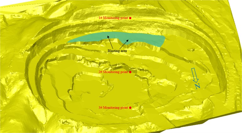
In order to mine the ore body, the ore body is broken by blasting and then transported to the treatment workshop. The formed slope is very close to the blasting point, about 30-40 m. Blasting vibration in close distance will inevitably cause serious impact on the slope. Fig. 3 shows the whole blasting process. Fig. 4 shows the blasting area and monitoring points in open-pit.
Fig. 3Blasting process in open-pit
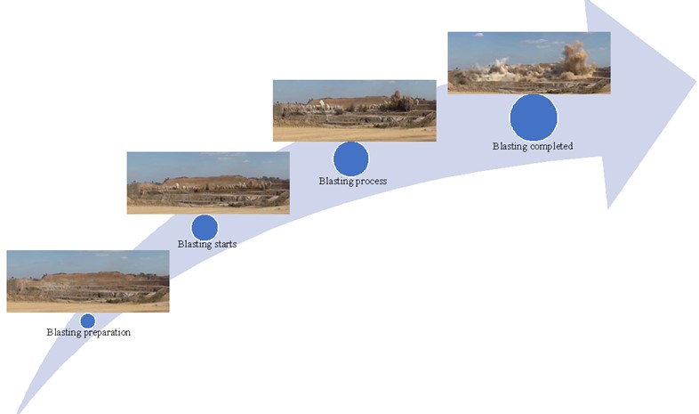
Fig. 4Blasting area and monitoring points in open-pit
3. Blasting vibration field test
3.1. Test equipment
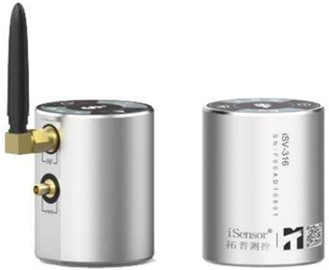
The isv-316 three-axis vibration intelligent sensor is an industry-leading wireless intelligent sensor, which integrates three-axis vibration sensor with digital measurement, storage and wireless transmission (as shown in Fig. 5). Based on the most advanced micro electromechanical, microelectronic measurement, wireless communication, embedded and innovative design and manufacture of wireless intelligent measurement terminal. The device supports a variety of wireless communication methods, connecting to the upper computer or automatically accessing the cloud. The device can automatically complete the measurement of vibration and inclination parameters such as three-dimensional velocity and acceleration, and can also be controlled wirelessly and remotely through mobile phones, tablets and PCs. The equipment is small in size, easy to carry, solid and beautiful. It is suitable for on-site measurement of engineering blasting vibration, health monitoring and inclination monitoring of engineering structures and large electromechanical equipment, and realizes distributed unattended on-line monitoring system.
Fig. 5isv-316 intelligent vibration monitor (http://m.topelec.com.cn/)
The isv-316 can not only carry out simple collection work, cooperate with ims-server to control the blasting vibration data through data acquisition equipment, but also carry out professional analysis, statistics and management of blasting vibration according to Sadowski's empirical formula. The software system consists of three parts: data playback, blasting vibration analysis and online monitoring. The data acquisition part mainly completes the functions of acquisition parameter setting, acquisition control, acquisition data storage and general analysis. The data analysis part mainly completes the functions of data acquisition (from equipment or files), data post management, data interception, data general analysis, special blasting vibration analysis, analysis conclusion report output, etc. Among them, the special blasting vibration analysis is based on the national standard of the safety code for blasting (GB 6722-2014), and the Sadovsky formula is used for blasting analysis and vibration speed prediction.
3.2. Blasting test
The complete blasting vibration measurement process is shown in Fig. 6, which can be divided into three parts: test parameter preparation, field test and data playback.
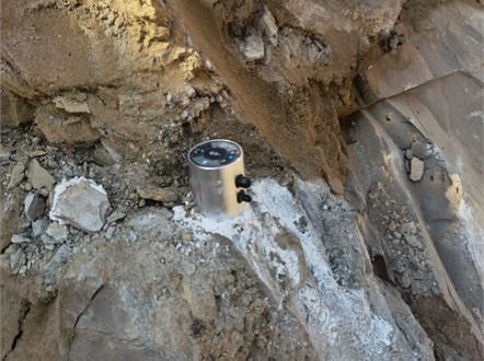
For the field test process, it is divided into the selection of vibration measurement monitoring points, cleaning monitoring points, on-site installation of vibration measurement instruments and on-site commissioning and inspection process. In the open pit, multiple measuring lines are selected outward according to the position of the blasting center. Find multiple original rock monitoring points on each survey line. Compare multiple monitoring points and select more appropriate monitoring points according to the distance, location, difficulty of installing instruments, etc. In order to make the instrument stick firmly to the original rock, it is necessary to clean the gravel soil of the original rock at the monitoring point. Then install the instrument on site. After installation, the monitoring instrument is opened for on-site debugging. The vibration measuring instrument installed on site is shown in Fig. 7. In this field blasting vibration measurement test, three isv-316 vibration monitors were used to measure the blasting vibration of the ore body.
In this field test, a new method for measuring blasting vibration in the open pit invented by the author is adopted, which is specially set for the slope topography of the open pit [20]. The main process is as follows: (1) According to the current topographic map of the slope, the precise orientation of the measuring line and the precise coordinates of the measuring points are determined. (2) In the field, GPS measuring instrument is used to find the coordinates of measuring points. The bedrock for installing the sensor is selected. The , and coordinates of the position of the bedrock are recorded. (3) The geological compass is used to accurately determine the orientation, and the sensor is installed. The invention can not only ensure that each sensor on the same layout line will not deviate from the layout line, but also ensure that the positive direction of the arrow of the sensor is aligned with the blasting center.
Fig. 6Flow chart of blasting vibration measurement
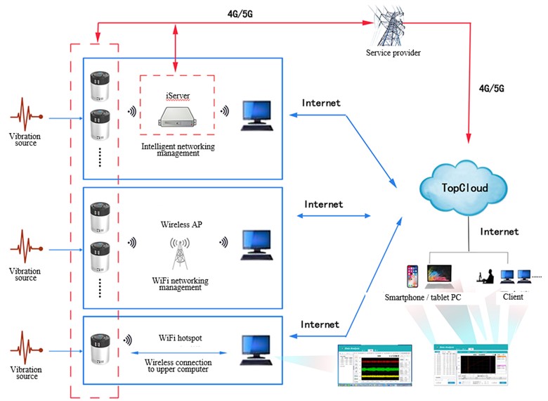
Fig. 7Vibration measuring instrument installed on site
3.3. Blasting test results
The ore body is broken by blasting at 1365 m steps in the northern mining area of the open pit. The blasting parameters are shown in Table 1, and the coordinates of the blasting center and the monitoring points are shown in Table 2.
After the monitoring instrument collects the blasting vibration data, the monitoring instrument is connected with the notebook computer indoors, and the test data is imported into the special analysis software. The obtained blasting waveform is shown in Fig. 8. The parameter statistics of each measuring point are shown in Table 3. The direction is the direction to aim at the blasting center. The direction is perpendicular to the direction in the horizontal plane. direction is the direction perpendicular to the horizontal plane. The blasting vibration rates in three directions were monitored by monitoring instruments.
Table 1Basic parameters of blasting in blasting area
Step height (m) | 6 | Borehole diameter (mm) | 152 |
Borehole inclination (°) | 90 | Chassis resistance line (m) | 3.8 |
Average hole depth (m) | 6.2 | Hole spacing (m) | 5 |
array pitch (m) | 4 | Charge length (m) | 3.2 |
Plugging length (m) | 3 | Explosive dosage (kg) | 7100 |
Number of blasting holes | 162 | specific charge (kg/m³) | 0.37 |
Maximum single shot dose (kg) | 55 | Blasting volume (m³) | 19000 |
Maximum distance of flying stone (m) | 400 | Explosive type | ANFO explosive |
Table 2Coordinates of blasting center and monitoring points
Serial number | |||
blasting center | 264233 | 291380 | 1365 |
1# Monitoring point | 264274 | 291445 | 1379 |
2# Monitoring point | 264289 | 291454 | 1394 |
3# Monitoring point | 264308 | 291477 | 1404 |
Table 3Parameter statistics of blasting vibration measurement points
Serial number | Vibration velocity (cm/s) | Main vibration frequency (Hz) | Maximum vibration velocity (cm/s) | Burst center distance (m) | |
1# Monitoring point | -direction | 1.9884 | 14.6484 | 2.1978 | 65.98 |
-direction | 1.2554 | 15.6250 | |||
-direction | 2.1978 | 14.6484 | |||
2# Monitoring point | -direction | 1.8050 | 18.5547 | 1.8050 | 80.83 |
-direction | 1.1795 | 18.5547 | |||
-direction | 0.8008 | 18.5547 | |||
3# Monitoring point | -direction | 1.3786 | 15.6250 | 1.3786 | 110.73 |
-direction | 0.9146 | 14.6484 | |||
-direction | 0.8509 | 15.6250 | |||
After the monitoring data is exported, the maximum vibration speed of 1# monitoring point is 2.1987 cm/s. The maximum vibration speed of the 2# monitoring point is 1.8050 cm/s. The maximum vibration speed of the 3# monitoring point is 1.3786 cm/s.
The allowable particle vibration speed standard for blasting vibration safety of permanent rock high slope in the Blasting Safety Code (GB6722-2014) is 10 Hz, 5-9 cm/s, 10 50 Hz, 8-12 cm/s, 50 Hz, 10-15 cm/s. The maximum blasting vibration speed monitored in this blasting is 2.1987 cm/s, and the main vibration frequency is 14.6484 Hz. Therefore, according to the standards in the regulations, the impact of this blasting on the slope meets the corresponding requirements.
According to the vibration velocity of the monitoring points obtained from the blasting vibration test, whether it has an impact on the slope stability can be qualitatively determined. However, the specific slope safety factor under the influence of blasting vibration needs to be obtained through limit equilibrium analysis, strength reduction method and other methods.
Fig. 8Waveform diagram of vibration measuring point test
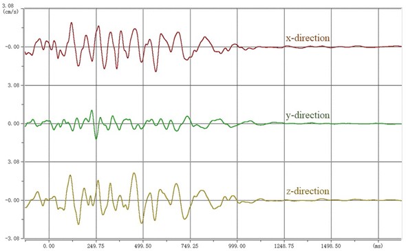
a) 1# measuring point
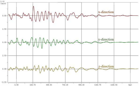
b) 2# measuring point
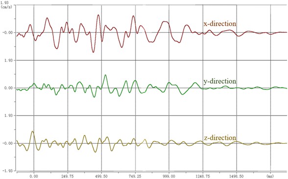
c) 3# measuring point
3.4. Blasting vibration coefficient
The response of blasting vibration depends on its own performance and vibration characteristics. The maximum vibration velocity of particles is often used as the main criterion for the different degrees of damage of buildings and structures. According to the calculation formula required in the safety code for blasting (GB6722-2014), the influence coefficient of blasting vibration is studied:
where is safety allowable distance of blasting vibration (m). is explosive quantity (kg). Simultaneous blasting is the total charge, and delayed blasting is the maximum charge. is safe allowable velocity of particle vibration (cm/s). and are the coefficient and attenuation index related to the topographic and geological conditions from the blasting point to the calculated protection object, which can be selected according to the safety regulations for blasting (GB6722-2014) or determined through field tests.
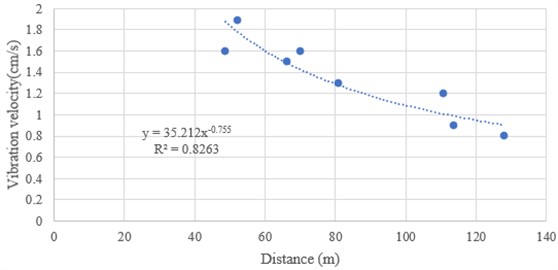
Blasting vibration is one of the main causes of damage to surrounding ground and underground buildings and structures. Blasting seismic wave is related to various factors, especially with charge quantity, distance, medium characteristics, blasting conditions, blasting methods and terrain. When studying and analyzing blasting vibration, three important parameters of vibration intensity, frequency and duration are generally considered as the basis for analyzing and evaluating blasting seismic effect. With the increase of distance, the vertical speed decreases, and its deceleration rate gradually decreases. The peak vertical velocity of particle vibration decreases exponentially with the increase of distance.
The original test results of open-pit blasting vibration are analyzed. According to the attenuation law of blasting seismic wave transmission, the abnormal point data are eliminated. Based on the horizontal and vertical data, the relationship between blasting particle vibration velocity v and proportional charge 1/3/ is regressed and fitted.
Horizontal direction in the area, the fitting formula is:
Vertical direction in the area, the fitting formula is:
The attenuation law of blasting seismic wave in the area is shown in Fig. 9.
In order to simplify the problem studied, it can be approximately assumed that when the seismic wave propagates in a uniform elastic medium, the particle moves in a simple harmonic motion. The magnitude of vibration can be characterized by vibration parameters such as displacement, velocity and acceleration. The mathematical relationship is expressed as the following formula.
The displacement formula is:
The velocity formula is:
The acceleration formula is:
where is maximum displacement of particle vibration (m). is angular frequency (Hz), . is vibration frequency (Hz).
Fig. 9Attenuation law of blasting seismic wave in the area
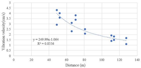
a) Horizontal direction
b) Vertical direction
From the above three mathematical relations Eqs. (4), (5) and (6), it can be seen that the vibration forms of displacement, velocity and acceleration of simple harmonic motion are basically similar. The difference is only the phase angle and amplitude. The ratio of acceleration amplitude to velocity amplitude is equal to an angular frequency. The acceleration can be calculated according to the particle vibration velocity measured on site, that is . The horizontal vibration frequency obtained from field monitoring is 7.8125-26.3672 Hz. The vibration frequency f of blasting main shock is taken as 16.6016 Hz in the horizontal direction. The vertical vibration frequency is 8.7891-19.5313 Hz. The vertical direction is 15.6250 Hz. The vibration acceleration can also be expressed by dividing the acceleration value by the gravitational acceleration. This ratio is usually called seismic coefficient, and the gravitational acceleration 981 cm/s2. By substituting the vibration frequency into the above formula, the calculation formula of vibration acceleration can be expressed as the following formula.
Horizontal direction in the area, the formula is:
Vertical direction in the area, the formula is:
The vibration acceleration is a momentum. When analyzing the slope stability, they must be converted into equivalent static load to participate in the calculation. When calculating the slope stability, the blasting vibration influence coefficient is used for analysis, and can be obtained according to the following formula:
Among them, the blasting dynamic conversion coefficient has become a very important parameter in the equivalent static calculation. For rock slope engineering, the value varies from 0.1 to 0.3. According to the experience of blasting vibration measurement in open-pit mines in China, the value is taken as 0.15. The values of vibration influence coefficient for different distances and dosage are shown in Table 4.
42 ms/17 ms surface detonators are used to detonate the open pit. The maximum single shot dosage is 48 kg and 55 kg. The maximum single shot dosage is generally 55 kg. Near the final slope, presplitting blasting is adopted to reduce the damage of blasting to the slope. In this slope stability analysis, the blasting vibration influence coefficient 0.032 when 40 m away from the final slope is used.
Table 4blasting vibration influence coefficient
Maximum single shot dose (kg) | Distance (m) | ||||
20 | 40 | 60 | 80 | 100 | |
48 | 0.066 | 0.032 | 0.021 | 0.015 | 0.012 |
55 | 0.069 | 0.033 | 0.022 | 0.016 | 0.013 |
4. Slope stability
4.1. Stability analysis parameters
The determination of allowable safety factor is the main index to evaluate slope stability. The calculation of slope safety factor is related to the depth and breadth of slope research, research methods, representativeness and reliability of selected parameters, slope height and slope angle, and people's understanding of many factors such as slope engineering geological and hydrogeological conditions. The allowable safety factor is often determined by engineering analogy and relevant design specifications.
According to the technical code for slope engineering of non-coal open pit mines (GB 51016-2014), the design safety factor of the overall slope under different load combinations shall meet the safety factor requirements specified in Table 5.
Therefore, according to the characteristics of engineering geology, hydrogeology, slope height and mining service life of the slope, and comparing with similar slopes, the allowable safety factors [k] under blasting vibration conditions is determined to be 1.18.
If the safety factor calculated by the profile is , it is stable. It is basically stable when , and unstable when 1.
The mechanical parameters of rock mass with different lithology are shown in Table 6.
Table 5Design safety factor of overall slope under different load combinations
Safety grade of slope engineering | Design safety factor of slope engineering | ||
Load combination I | Load combination II | Load combination III | |
Ⅰ | 1.25-1.20 | 1.23-1.18 | 1.20-1.15 |
Ⅱ | 1.20-1.15 | 1.18-1.13 | 1.15-1.10 |
Ⅲ | 1.15-1.10 | 1.13-1.08 | 1.10-1.05 |
Note: 1) Load combination I is self-weight + groundwater; Load combination II is self-weight + groundwater + blasting vibration force; Load combination III is self-weight + groundwater + seismic force. 2) For step slope and temporary working slope, a certain degree of damage is allowed, and the design safety factor can be appropriately reduced. | |||
Table 6Mechanical parameters of rock mass with different lithology
Surrounding rock | Bulk. density (kN·m3) | Elastic modulus (MPa) | Poisson ratio | Cohesion (kPa) | Internal friction angle (°) |
Quaternary soil | 16.3 | 200.00 | 0.30 | 17.00 | 20.50 |
Tectonic breccia | 26.1 | 3512.12 | 0.21 | 460.00 | 28.00 |
Dolomite | 27.6 | 7110.34 | 0.24 | 720.00 | 33.59 |
Dolomitic shale | 23.2 | 3124.23 | 0.25 | 452.00 | 29.65 |
4.2. Stability analysis
The limit equilibrium analysis adopts the slide6.0 software of Rocscience company. Slide is a program for calculating the stability of two-dimensional soil and rock slopes. It can calculate the safety factor and possible failure probability of the slope, and can automatically search the potential failure sliding surface of arc and non-arc. Slide is very convenient for operation and application. Even complex models can be quickly and easily established and calculated and analyzed. External loads, groundwater and supports can be simulated in different ways. Slide uses the vertical slice method based on limit equilibrium (such as bishop, Janbu, Spencer and other different methods) to calculate the stability of the slope. Each sliding surface can be calculated and analyzed, and the location of the most dangerous potential failure sliding surface of the calculated slope can be determined by the search algorithm. Deterministic data (safety factor) or reliability analysis can be carried out.
Because the simplified Bishop method, Spencer method and Morgen Prince method are widely used in the analysis and calculation of limit equilibrium of open-pit slope, the value of slope safety factor under circular arc sliding state and non-circular arc sliding state can reflect the actual state of slope stability. The calculation method has the advantages of fast calculation speed and reliable results, so the calculation results of these three methods are taken as the basis of this stability study.
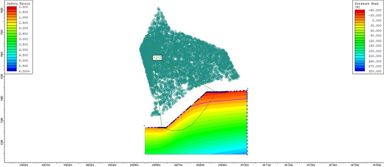
Considering the factors such as the occurrence of the structural plane of the slope rock mass and the complexity of the lithology, the non-circular arc sliding calculation method is used for calculation and analysis in the analysis process. The analysis results are shown in Table 7 and Fig. 10.
Table 7Calculation results of safety factor
Calculation method | Bishop | Spencer | Morgen-Prince |
Safety factor | 1.217 | 1.219 | 1.311 |
The safety factor of the analysis section at the 45° slope angle is 1.217, which meets the requirements of the allowable safety factor. It shows that the slope can maintain stability under the influence of blasting vibration.
Morgen Prince method and Spencer method generally have higher safety factors than Bishop method, and the non-circular slip surface shape leads to irregular changes in the calculated safety factors and slope angles. From the perspective of safety, the minimum safety factors of the three calculation methods are used as the basis for judging slope stability.
The blasting mining of open pit ore body is bound to affect the slope stability. The research on the effect of blasting vibration in open pit is the foundation to ensure the safety of open pit mining. In order to accurately evaluate the slope stability of the open pit, the blasting vibration test must be carried out on the open pit site to obtain the blasting vibration data. Based on several test data, the influence coefficient of blasting vibration is analyzed by fitting analysis method, and finally the influence coefficient value is obtained. Based on the influence coefficient of blasting vibration, the limit equilibrium analysis software is used to calculate the slope safety factor under the action of blasting vibration force. The slope stability is evaluated. The field blasting vibration test provides data basis for slope stability simulation analysis.
Fig. 10Safety factor of non-circular slip slope in Bishop calculation method
5. Conclusions
Blasting mining in open pit has a significant impact on the adjacent slope, which often causes the rock mass cracking and spalling of the slope to form a landslide disaster. In order to explore the impact of blasting vibration on the adjacent slope, field tests were carried out with professional testing equipment, and several blasting vibration data were measured. The Sadovsky formula is used for fitting analysis, and the influence coefficient of blasting vibration was obtained. The slope stability analysis was carried out by using the limit equilibrium analysis software SLIDE, and the slope safety factor under the influence of blasting vibration was obtained. The following conclusions can be drawn.
1) The maximum blasting vibration speed monitored in this blasting is 2.1987 cm/s, and the main vibration frequency is 14.6484 Hz. Therefore, according to the standards in the regulations, the impact of this blasting on the slope meets the corresponding requirements.
2) With the increase of distance, the vertical speed decreases, and its deceleration rate gradually decreases. The peak vertical velocity of particle vibration decreases exponentially with the increase of distance.
3) The maximum single shot dosage is generally 55 kg. Near the final slope, presplitting blasting is adopted to reduce the damage of blasting to the slope. In this slope stability analysis, the blasting vibration influence coefficient 0.032, when 40 m away from the final slope is used.
4) Morgen Prince method and Spencer method generally have higher safety factors than Bishop method, and the non-circular slip surface shape leads to irregular changes in the calculated safety factors and slope angles. From the perspective of safety, the minimum safety factors of the three calculation methods are used as the basis for judging slope stability.
5) The safety factor of the analysis section at the 45° slope angle is 1.217, which meets the requirements of the allowable safety factor. It shows that the slope can maintain stability under the influence of blasting vibration.
References
-
X.-Y. Jiang, P. Cui, and C.-Z. Liu, “A chart-based seismic stability analysis method for rock slopes using Hoek-Brown failure criterion,” Engineering Geology, Vol. 209, pp. 196–208, Jul. 2016, https://doi.org/10.1016/j.enggeo.2016.05.015
-
Y. You, H. Pan, J. Liu, and G. Ou, “The optimal cross-section design of the “Trapezoid-V” shaped drainage canal of viscous debris flow,” (in Chinese), Journal of Mountain Science, Vol. 8, No. 1, pp. 103–107, Feb. 2011, https://doi.org/10.1007/s11629-011-1023-0
-
M. Chen, W. Lu, P. Yan, and C. Zhou, “New method for dynamic stability analysis of rock slope under blasting vibration based on equivalent acceleration and Sarma method,” Canadian Geotechnical Journal, Vol. 51, No. 4, pp. 441–448, Apr. 2014, https://doi.org/10.1139/cgj-2012-0475
-
X. F. Deng, J. B. Zhu, S. G. Chen, Z. Y. Zhao, Y. X. Zhou, and J. Zhao, “Numerical study on tunnel damage subject to blast-induced shock wave in jointed rock masses,” Tunnelling and Underground Space Technology, Vol. 43, pp. 88–100, Jul. 2014, https://doi.org/10.1016/j.tust.2014.04.004
-
X. F. Deng, S. G. Chen, J. B. Zhu, Y. X. Zhou, Z. Y. Zhao, and J. Zhao, “UDEC-AUTODYN hybrid modeling of a large-scale underground explosion test,” Rock Mechanics and Rock Engineering, Vol. 48, No. 2, pp. 737–747, Mar. 2015, https://doi.org/10.1007/s00603-014-0600-2
-
Y. Hu, W. Lu, M. Chen, P. Yan, and J. Yang, “Comparison of blast-induced damage between presplit and smooth blasting of high rock slope,” Rock Mechanics and Rock Engineering, Vol. 47, No. 4, pp. 1307–1320, Jul. 2014, https://doi.org/10.1007/s00603-013-0475-7
-
X. Song, “Influence of blasting on the properties of weak intercalation of a layered rock slope,” International Journal of Minerals, Metallurgy and Materials, Vol. 16, No. 1, pp. 7–11, Feb. 2009, https://doi.org/10.1016/s1674-4799(09)60002-9
-
Z. Y. Zhang, L. F. Luan, J. Yao, J. B. Xie, and X. L. Li, “Study on the influence of stability for higher precipitous open pit slope under mining blasting,” in Advanced Materials Research, Vol. 255-260, pp. 3822–3826, May 2011, https://doi.org/10.4028/www.scientific.net/amr.255-260.3822
-
D.-W. Zhong and L. Wu, “Model test and numerical simulation for dynamic characteristics of rock slope under blasting loads,” (in Chinese), Proceedings of the 10th Asia-Pacific Conference, Vol. 29, May 2011, https://doi.org/10.1142/9789814324052_0081
-
J. B. Zhu, X. F. Deng, X. B. Zhao, and J. Zhao, “A numerical study on wave transmission across multiple intersecting joint sets in rock masses with UDEC,” Rock Mechanics and Rock Engineering, Vol. 46, No. 6, pp. 1429–1442, Nov. 2013, https://doi.org/10.1007/s00603-012-0352-9
-
H. R. Mohammadi Azizabadi, H. Mansouri, and O. Fouché, “Coupling of two methods, waveform superposition and numerical, to model blast vibration effect on slope stability in jointed rock masses,” Computers and Geotechnics, Vol. 61, pp. 42–49, Sep. 2014, https://doi.org/10.1016/j.compgeo.2014.04.008
-
N. Kumar Bhagat, A. K. Mishra, R. K. Singh, C. Sawmliana, and P. K. Singh, “Application of logistic regression, CART and random forest techniques in prediction of blast-induced slope failure during reconstruction of railway rock-cut slopes,” Engineering Failure Analysis, Vol. 137, p. 106230, Jul. 2022, https://doi.org/10.1016/j.engfailanal.2022.106230
-
C. Yi, D. Johansson, and J. Greberg, “Effects of in-situ stresses on the fracturing of rock by blasting,” Computers and Geotechnics, Vol. 104, pp. 321–330, Dec. 2018, https://doi.org/10.1016/j.compgeo.2017.12.004
-
X. Li et al., “Mechanical properties of rock under coupled static-dynamic loads,” Journal of Rock Mechanics and Geotechnical Engineering, Vol. 1, No. 1, pp. 41–47, Oct. 2009, https://doi.org/10.3724/sp.j.1235.2009.00041
-
Z. Wang, H. Wang, J. Wang, and N. Tian, “Finite element analyses of constitutive models performance in the simulation of blast-induced rock cracks,” Computers and Geotechnics, Vol. 135, p. 104172, Jul. 2021, https://doi.org/10.1016/j.compgeo.2021.104172
-
J. Dai et al., “Study on the mechanism of displacement mutation for jointed rock slopes during blasting excavation,” International Journal of Rock Mechanics and Mining Sciences, Vol. 150, p. 105032, Feb. 2022, https://doi.org/10.1016/j.ijrmms.2021.105032
-
H. Zheng, T. Li, J. Shen, C. Xu, H. Sun, and Q. Lü, “The effects of blast damage zone thickness on rock slope stability,” Engineering Geology, Vol. 246, pp. 19–27, Nov. 2018, https://doi.org/10.1016/j.enggeo.2018.09.021
-
R. F. E. Silva, A. C. Zingano, R. R. Lima, J. P. D. Silva, and C. C. Holanda, “Influence of geomechanical analysis on the stability of ornamental rock slopes,” Journal of South American Earth Sciences, Vol. 116, p. 103859, Jun. 2022, https://doi.org/10.1016/j.jsames.2022.103859
-
N. Jiang, C. Zhou, S. Lu, and Z. Zhang, “Propagation and prediction of blasting vibration on slope in an open pit during underground mining,” Tunnelling and Underground Space Technology, Vol. 70, pp. 409–421, Nov. 2017, https://doi.org/10.1016/j.tust.2017.09.005
-
F. F. Wang et al., “A method for measuring blasting vibration in open pit,” Hunan Province: CN110736537B, 2021.
About this article

This work was supported by the Key Project of Chongqing Natural Science Foundation (CSTC20JCYJ-ZDXMX0012).
The datasets generated during and/or analyzed during the current study are available from the corresponding author on reasonable request.
Can Liu, Feifei Wang and Bin Chen wrote the manuscript. Qingyang Ren and Songjun Cui provided a field test plan. Can Liu, Honghua Jin and Ziqiang Zhu carried out numerical simulation research. Feifei Wang, Honghua Jin and Ziqiang Zhu carried out the field tests.
The authors declare that they have no conflict of interest.
