Abstract
In order to improve the efficiency of using land resources and relieve the tension of urban land, the property covered by metro depot rapidly carries out planning and construction in many cities. However, train-induced vibration will propagate upward due to the soil-foundation dynamic interaction, which may affect the vibration comfort of the residents of the overlying property. In this paper, a metro depot superstructure of Foshan Metro was selected to study the environment vibration impact. Based on the finite element method to predict the building vibration. Thus, it lays a foundation for the prediction and evaluation of environmental vibration of metro depot with cover complex. The results found that the proposed model could simulate the vibration attenuation law caused by subway train well in time domain. Both vibration and structural radiated noise are within the standard limits, indicating that the vibration caused by train operation has little influence on buildings.

Highlights
- Proposed model could simulate the vibration attenuation law caused by subway train well.
- A metro depot superstructure of Foshan Metro was selected to study the environment vibration impact.
- Both vibration and structural radiated noise are within the standard limits.
1. Introduction
Subway train operates on the track, due to the moving vehicle axle load loading and wheel/rail irregularity as well as the dynamic interaction between wheel and rail, causing the vibration of vehicle system and track structure. When the vibration mechanical wave meets the structure foundation or the platform foundation, the vibration will propagate upward due to the soil-foundation dynamic interaction, which may affect the vibration comfort of the residents of the overlying property.
As a place for parking, inspection, preparation, application and repair of subway vehicles, metro depot occupies a large area. In order to improve the efficiency of using land resources and relieve the tension of urban land, the property covered by metro depot rapidly carries out planning and construction in many cities (Fig. 1). Although the motor, ventilation system and maintenance machinery operation of subway vehicles also produce vibration and noise, the most significant vibration source is the vibration and radiated noise generated by subway train operation [1, 2]. According to the classification of the functional areas of metro depot, the areas with greater vibration influence mainly include the test line with higher speed, u-shaped groove, throat area and access section line with more rail joints, switches and curved track, and the impact of parking depot is relatively small. In addition, due to the relatively concentrated vibration generation period caused by train operation in the throat area of metro depot, mainly occurs in the morning departure period (05:00-08:30), evening peak departure period (15:30-17:00) and evening collection period (20:00-24:00). Considering the particularity of vibration generation period, it may affect the residents of the above property greatly [3]. Therefore, it is necessary to predict the vibration caused by subway operation, so as to take feasible measures to reduce vibration and reduce the influence of vibration.
Empirical method is one of the important means of vibration prediction. It is based on theoretical research and a large number of field test data, considering the distance between vibration source and vibration body, wheel/rail force, train speed, vibration attenuation and other factors, and then formed an empirical formula to guide vibration evaluation. At present, the empirical prediction and evaluation model proposed by United States Federal Railroad Administration (2012) [4] based on the measured ground vibration data caused by train operation is widely used in foreign countries. Based on the set benchmark vibration value, the model modifies the vibration source, propagation path, vibration body and other factors to obtain the vibration influence value at the vibration body. Judging from the current literature, empirical method to predict work simple quickly, but the low precision and reliability, is a relatively simple mathematical expressions. The complex soil-pile interaction and the vibration propagation of the overburden structure cannot be accurately and quantitatively predicted in the frequency domain. It can only be applied in the feasibility study stage to judge the sensitive range and degree of vibration influence.
Fig. 1Typical metro depot superstructures

Numerical model is a mature analysis method, and finite element method is the most commonly used method. The main advantage is that it can simulate objects with complex geometric shapes and boundary conditions. Balendra (1989) [5], Kouroussis et al. (2011) [6], Connolly et al. (2013) [7] studied the propagation mechanism of environmental vibration caused by subway train operation and the prediction and evaluation of building vibration in time domain by using finite element method. However, the finite element model is seldom used to study the metro depot.
In this paper, a metro depot superstructure of Foshan Metro was selected to study the environment vibration impact. Based on the finite element method to predict the building vibration. Thus, it lays a foundation for the prediction and evaluation of environmental vibration of metro depot with cover complex, and provides a scientific basis for the optimization design of environmental vibration control measures of metro depot, which has great theoretical and engineering application value.
2. Project summary
The metro depot is located in the south of Pingsheng Avenue, with a length of about 1040 m and a width of about 570 m, covering a total area of about 27.8 hectares. The current site selection is workshop, green space, etc., which is planned as rail transit land. The current site is relatively flat terrain. The site is located at Pingzhou Waterway on the north, Pingnan Industrial Zone on the east, Taifeng industrial zone on the south and Pingsheng Bridge on the west.
The metro depot has 46 parking lots, 4 parking lots for biweekly/march inspection, 3 parking lots for fixed repair and 1 parking lot for temporary repair. In addition, there are emergency rescue base and online storage and logistics center in the future (the white area in the general plane of the upper cover is not reserved and the investment company needs to negotiate with the operation headquarters whether to reserve). The parking depot is 297.5 m long, 180 m wide and covers an area of 49,344 m2. There are 23 lanes of stop and check lines, and each lane is set by 1 lane and 2 rows, a total of 46 rows. The maintenance warehouse is a terminal type, set on the south side of the conditioning engineering warehouse. The maintenance warehouse is composed of purging warehouse, fixed/temporary repair warehouse, static adjustment line and auxiliary maintenance workshop. There are 3 fixed repair lines, 1 temporary repair, 1 static adjustment, 1 cleaning. The test line is arranged at the outermost end of the north side of the vehicle base. The whole line is designed as flat slope.
For the vibration reduction and noise reduction of the property development on the upper cover, it is necessary to focus on the low and middle frequency influence of the test line section with high driving speed. The high and middle frequency influence of the U-shaped groove, the high and middle frequency influence of the access line and throat area, and part of the parking depot. The main areas of vibration and noise control are test line, U slot, access line and throat area.
There are many switches in and out of the section line, and the vibration noise is relatively large. As with the throat area, every day the receiving and receiving cars of the train must pass through the inbound and outbound segments and cause vibration. In addition, the speed of U-shaped tank is second only to that of the test line, and there is a small radius curve, so the buildings near the U-shaped slot need to be considered.
3. Numerical model
Firstly, the vehicle system sub-model and the track system sub-model are established to form the vehicle-track interaction dynamic model, considering the interaction between train vehicle, rail, rail underlay and fastener, sleeper, ballast and foundation. The Hertz nonlinear contact theory was used to calculate the wheel-rail contact, and the time domain simulation samples based on the track irregularity were used as the external excitation input of the wheel-rail irregularity. Newmark implicit integral method was used to solve the dynamics equations of the vehicle system and the track system respectively through the wheel-rail displacement compatibility and force balance coordination. The wheel-rail disharmony was used as the excitation to solve the change of wheel-rail coupling contact force with time.
By using finite element method, a three-dimensional finite element model of track structure-surrounding strata and overlaying building is established. By programming a moving load subprogram, the wheel-rail coupling contact force calculated by the vehicle-track coupling dynamic analysis model was used as moving load, and the dynamic response caused by train operation was obtained. The effectiveness of the proposed method is verified by comparing the numerical simulation value with the field measured value.
(1) Vehicle model.
Subway vehicles use type B trains. The calculated dynamic wheel-rail contact force is used as the input parameter of moving load, which is loaded by subroutine and acts on the track structure.
(2) Track structure.
Ballasted road bed as an example, track and road bed model by rail, fastener, sleeper, road bed (surface layer, ballast) composition. The gauge is 1435 mm, the whole seamless line. A total of 1680 sleepers per kilometer are set. The ballast is 0.45 m thick.
(3) Soil.
According to borehole data and shear wave velocity of each layer, the soil layer of the model can be simplified into four layers and simulated by linear elastic model.
The size of the finite element model of foundation soil is 150×150×55 (length, width and height, unit: m), as shown in Fig. 2. The main physical and mechanical parameters of foundation soil model are shown in Table 1.
Table 1Physical and mechanical parameters of soil layers
Layers | Thickness (m) | Density (Kg/m³) | Modulus of elasticity (MPa) | Poisson’s ratio | Shear wave velocity (m/s) | Damping ratio |
Artificial filled soil | 1.7 | 1.83 | 202.5 | 0.471 | 190.0 | 0.03 |
Silt soil | 10.0 | 1.64 | 145.8 | 0.475 | 162.0 | 0.03 |
Sand | 2.5 | 1.80 | 201.5 | 0.470 | 225.4 | 0.03 |
Sandstone | ∞ | 2.2 | 372.1 | 0.442 | 240.2 | 0.03 |
Fig. 2Finite element model of soil
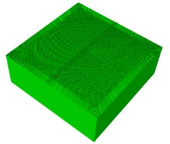
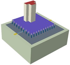
Fig. 3Building model
(4) Building.
The building structure model is established, beam element is used to simulate beams and frame columns, and shell element is used to simulate walls and floors. The interaction between soil and structure can be effectively reflected by using Embed contact.
Based on the vibration propagation mechanism, the numerical model adopts the foundation separation mode, that is, the track structure foundation is separated from the building foundation structure, so as to avoid the vibration wave directly spreading from the track structure to the overlying building, resulting in large vibration. The building model is shown in Fig. 3.
(5) Boundary conditions.
When the finite discrete model is used to simulate infinite natural foundation, the biggest problem of artificial truncated boundary is that the vibration wave will be reflected on the artificial boundary interface, so that the vibration energy cannot be transmitted back to the analysis area, resulting in simulation distortion. The research experience of many scholars shows that the coupling analysis of finite element and infinite element has a wide application in the simulation of infinite domain. By setting the soil in the outermost element of the model as an infinite element, and introducing attenuation formula on the boundary to simulate the radiation damping of infinite foundation without losing the calculation accuracy, the radiation energy of vibration is gradually attenuated outwardly, which can prevent the reflection of wave from interfering the calculation of the model.
Fig. 4Comparison of calculated vibration and measured vibration in time history
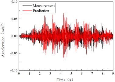
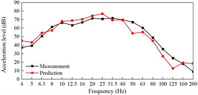
Fig. 5Comparison of calculated vibration and measured vibration in frequency
(6) Model verification.
Figs. 4 and 5 shows the time domain and frequency domain plots of the vertical acceleration of ground vibration at a distance of 28 m from the track, and compares them with the measured values of the vertical acceleration near the ground. It can be found that the calculated acceleration amplitude is very close to the measured acceleration amplitude. This model can simulate the vibration attenuation law caused by subway train well in time domain.
4. Results
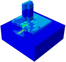
The finite element model of the building was established to predict the vibration response caused by train operation under the condition that no vibration mitigation measures were taken. During the calculation, the maximum vibration level of the most unfavorable position of each floor is taken as the calculation result, and then the actual calculation result is compared with the standard vibration limit value, so as to choose whether to add vibration reduction measures and evaluate the vibration reduction effect of each vibration reduction measure. Fig. 6 is a representative finite element cloud diagram of train induced vibration propagation in a building. Fig. 7 shows the variation prediction of vibration and radiated noise caused by train operation with building floors.
Fig. 6Finite element cloud diagram
The maximum Z-vibration level calculated by GB10070-88 standard weighting method is 50-59 dB, which is about 8 dB lower than the night limit of the standard. With the increase of the floor, the vibration gradually attenuated at the 1-21 floor and amplified at the 21-31 floor.
Fig. 7Prediction of vibration and radiated noise
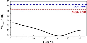
a) The maximum vibration level varies with the floor
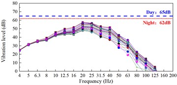
b) The variation law of maximum frequency division vibration level with floor
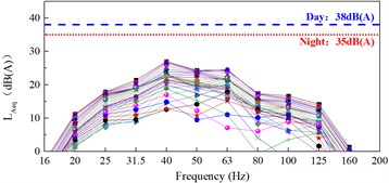
c) The variation law of structure radiated noise with floor
The maximum frequency division vibration level calculated by the weighting method of JGJ/T 170-2009 is 47-57 dB, and the frequency of the maximum vibration level is 20 Hz and 25 Hz, which are in the lower frequency band. The maximum frequency division level is about 5 dB below the night limit of the standard. In the range of 4-10 Hz, the vibration changes little with the floor; In the frequency range of 12.5-200 Hz, the vibration attenuates with the rise of the floor, and there is a certain amplification near the top floor.
The maximum equivalent sound level of secondary noise calculated by JGJ/T 170-2009 specification is 15-21 dB (A), which is far lower than the specification limit.
5. Conclusions
In this paper, a metro depot superstructure of Foshan Metro was selected to study the environment vibration impact. Based on the finite element method to predict the building vibration. Thus, it lays a foundation for the prediction and evaluation of environmental vibration of metro depot with cover complex, and the following conclusions are drawn:
1) The calculated acceleration amplitude is very close to the measured acceleration amplitude. The proposed model can simulate the vibration attenuation law caused by subway train well in time domain.
2) Both vibration and structural radiated noise are within the standard limits, indicating that the vibration caused by train operation in this area has little influence on buildings.
References
-
C. Zou, Y. Wang, J. A. Moore, and M. Sanayei, “Train-induced field vibration measurements of ground and over-track buildings,” Science of The Total Environment, Vol. 575, pp. 1339–1351, Jan. 2017, https://doi.org/10.1016/j.scitotenv.2016.09.216
-
C. Zou, Y. Wang, P. Wang, and J. Guo, “Measurement of ground and nearby building vibration and noise induced by trains in a metro depot,” Science of The Total Environment, Vol. 536, pp. 761–773, Dec. 2015, https://doi.org/10.1016/j.scitotenv.2015.07.123
-
M. Saitoh, “On the performance of lumped parameter models with gyro‐mass elements for the impedance function of a pile‐group supporting a single‐degree‐of‐freedom system,” Earthquake Engineering and Structural Dynamics, Vol. 41, No. 4, pp. 623–641, Apr. 2012, https://doi.org/10.1002/eqe.1147
-
U. Basu, “Explicit finite element perfectly matched layer for transient three‐dimensional elastic waves,” International Journal for Numerical Methods in Engineering, Vol. 77, No. 2, pp. 151–176, Jan. 2009, https://doi.org/10.1002/nme.2397
-
T. Balendra, K. H. Chua, K. W. Lo, and S. L. Lee, “Steady-state vibration of subway-soil-building system,” Journal of engineering mechanics, Vol. 115, pp. 145–162, 1989.
-
G. Kouroussis, O. Verlinden, and C. Conti, “Free field vibrations caused by high-speed lines: Measurement and time domain simulation,” Soil Dynamics and Earthquake Engineering, Vol. 31, No. 4, pp. 692–707, Apr. 2011, https://doi.org/10.1016/j.soildyn.2010.11.012
-
D. Connolly, A. Giannopoulos, and M. C. Forde, “Numerical modelling of ground borne vibrations from high speed rail lines on embankments,” Soil Dynamics and Earthquake Engineering, Vol. 46, pp. 13–19, Mar. 2013, https://doi.org/10.1016/j.soildyn.2012.12.003
About this article

