Abstract
Robots require a certain set of skills to perceive and analyse the environment and act accordingly. For tracked mobile robots getting good odometry data from sensory information is a challenging key prerequisite to perform in an unstructured dynamic environment, thus an essential issue in the tracked mobile robotics domain. In this article, we construct a ROS-based tracked mobile robot system taking the Jaguar V4 mobile robot as the base platform. On which several visual odometry solutions based on different cameras and methods (Intel RealSense T265, Zed camera, RTAB-Map RGBD) are integrated and benchmark comparison is performed. Analysis of new challenges faced by different methods while applied on a tracked vehicle as well as recommendations and conclusions are presented. Intel RealSense T265 solution proved to perform well in uncertain conditions which involves bounded vibrations and low lighting conditions with low latency, which result in good map generation. Further evaluations with a path planning algorithm and Intel RealSense T265 were conducted to test the effect of the robot’s motion profiles on odometry data accuracy.
1. Introduction
Nowadays robots are being used in various applications within health care [1], agriculture [2], food preparation [3], industrial machinery [4], manufacturing [5], military [6] or in a collaboration with humans [7] and other sectors. To tackle today’s and future challenges robots require a distinct set of skills to perceive and analyse the environment and act accordingly [8]. For mobile robots the navigation system is one of the key prerequisites to perform in a dynamic environment, thus an essential issue in the mobile robotics domain [9]. Mobile robotics has received a great deal of attention in the past decades, for example, the market for professional service robots grew in 2020 by 12 % [10]. Moreover, the breakthrough of the covid-19 virus made an urgent demand for mobile robots to help fight the virus [11]. For example, the demand for professional cleaning robots grew by 92 % in terms of units sold [10]. In most of these new applications, the robot needs to be autonomous and to be able to reason about the environment and take decisions accordingly. Most of the environments nowadays where these robots are deployed can be highly unstructured, partially observable, and potentially inaccessible/human un- friendly.
Mobile land-based robots can be classified into four main categories according to how they move: wheeled, tracked, legged and hybrid [12]. The most widely adopted among all of them is the wheeled robots as they are relatively easy to control and localize. There are already many autonomous wheeled mobile robots successfully deployed in different fields as warehousing and delivery [13]. However, these robots are more suitable for constrained environments that have smooth planar terrain. For unconstrained environments tracked vehicles are more suitable as they can move on uneven terrain, climb slopes, and reach inaccessible areas where mobile wheeled robots cannot reach.
Tracked vehicles offer various advantages for locomotion because of their large contact area, which allows them to adapt passively to uneven terrain. Therefore, such mechanisms allowed these robots to be utilized in different applications as search and rescue in disaster areas that might involve operations in collapsed buildings and underground stairs [14]. However, robots with such mechanisms are prone to slip and this slippage generates large, accumulated position and orientation errors in robot localization. In recent years, various new odometry calculation and localization techniques are developed to replace the conventional encoder based odometry solutions [15].
The goal of this article is twofold. First, we construct the tracked mobile robot system taking the Jaguar V4 [16] mobile robot as the base platform. The proposed system is built from discrete components, therefore maximizing the modularity of the system. Second, we integrate, adjust, and compare different visual odometry methods. Even though the intended use of the Jaguar robot as the base platform is to exploit the benefits of the tracked mobile robots for addressing the terrain issues, in this article the experiments and tests are performed in a simplified laboratory environment. Taking into account the above mentioned the rest of the paper is organized as follows: Section 2 presents the developments in the field of tracked mobile robots, visual odometry (VO) methods and their comparisons. Section 3 describes the experimental setup of ROS based autonomous navigation system built upon the Jaguar robot. Section 4 describes different aspects of tested VO methods and illustrates the comparison between them. The obtained results in detail are analysed in Section 5, the accuracy of the chosen VO method is evaluated with different motion profiles in Section 6 and Section 7 concludes this article.
2. Related work
2.1. Tracked mobile robots
A tracked robot such as ATLAS [17] and hybrid tracked-wheeled multi-directional mobile robot [18] was developed to locomote over a range of ground conditions such as snow, sandy soil, mud, steep slopes, rubble-strewn terrain, or any combination of these that traditional wheeled mobile robots couldn’t handle. Together with advantages, the tracked robots also face some challenges in position tracking through motor encoders due to track drifts and slips. In [19] an indirect Kalman filter was applied on Fitorobot for localisation and eliminating the errors caused due to slipping tracks in encoder based odometry. Assuming that the robot can navigate in 2D a fuzzy logic controller with perception feedback for a tracked robot to identify stairs, ascending and descending on them was developed in [20]. Markov Decision Process (MDP) was used in [21] for achieving vision-based autonomous navigation policy by utilizing the Intel RealSense depth camera and a LIDAR sensor. Deep Reinforcement Learning (DRL) was applied to learn collision-free autonomous navigation in changing environments. Further on, tracked vehicles also induce vibrations which negatively affect vision-based navigation systems. Tracked mobile robot with a unique passive suspension that is built utilizing a bio-inspired animal-limb-like strategy to ensure both loading capacity and vibration isolation performance was proposed in [22]. A mobile parallel robot (MPR), driven by three tracked vehicles was designed in [23]. A genetic algorithm (GA) was applied to overcome the complex coupling of the robot. Trajectories based on the Bézier curve were used for avoiding obstacles. In [24], gap width detection is done and an autonomous gap traversing motion is designed using hexapods on a tracked vehicle. To reduce the slip compensation in the odometry of a tracked mobile robot, a Hardware-in-the-loop (HIL) simulation approach was utilised for monitoring and analysing the performance [25]. Considering the slippage issues in tracked robots, [26] applied the H-infinity Kalman filter as a robust state estimator. An autonomous navigation system was designed for a crawler-type autonomous ground vehicle (AGV) based on a robot operating system (ROS) [27]. The test was performed in a simulated environment which was developed in Gazebo.
2.2. Vision-based odometry
Three main approaches can be used to estimate the position of a mobile robot using vision-based odometry: feature-based technique, appearance-based approach, or a hybrid of feature- and appearance-based approach [28]. In a feature-based approach, the image matched to a prior one is done by comparing each feature in both photos and computing the Euclidean distance of feature vectors to find candidate matching features. After that, the displacement is calculated by calculating the velocity vector between the points that have been detected [29]. In an appearance-based approach rather than extracting and tracking characteristics, the changes are monitored in the look of acquired images and the intensity of pixel information inside them as implemented by [30]. In some cases, a hybrid method, which combines feature- and appearance-based approaches, is the best option. Which is a combination of tracking salient characteristics across frames and pixel intensity information from the entire or batch of images. Due to a fact that the appearance-based technique alone was not very robust to picture occlusions, the hybrid approach was devised in [31]. As a result, in their research, ground plane image attributes were utilized to estimate vehicle translation, whereas picture appearance was employed to estimate vehicle rotation.
Since Visual Odometry (VO) is termed as the pose estimating procedure of an entity (e.g., a vehicle, a human, or a robot), it can be computed simply using a stream of images received from a single or several cameras attached to it [32]. By analysing the image sequences acquired by a camera, VO delivers an incremental online estimation of a vehicle's position [33]. Using cameras for robot localization provides several advantages over using other sensors, including cost savings, the ability to easily integrate ego-motion data into other vision-based algorithms, such as obstacle, pedestrian, and lane detection, and the elimination of the requirement for sensor calibration [34]. Therefore, instead of using expensive systems (Global Positioning System (GPS), Inertial Navigation System (INS), and laser-based localization systems) to estimate robot location, using a consumer-grade camera is a simple and inexpensive way [35]. VO is more feasible than wheel odometry as wheel slippage on uneven terrain or other unfavourable conditions had little effect on it. Furthermore, VO is also useful in GNSS-denied environments and thus this technique does not release any detectable information into the environment, unlike laser and sonar localization techniques [36].
2.3. Benchmark comparisons of visual odometry algorithms
Throughout the year's several benchmark comparisons of VO algorithms have been proposed, usually focusing on the localization of wheeled mobile robots. A comparison between Real-Time Appearance Based Mapping (RTAB-MAP) and Oriented Fast and Rotated Brief (ORB) Simultaneous Localisation and Mapping (SLAM), was done in [37] and their tests proved that the trajectory estimation by RTAB-Map is accurate but odometry is not as accurate as ORB SLAM. Three off-the-shelf odometry systems were compared with OptiTrack ground truth information in [38], where Intel RealSense T265 and Zed mini provided comparable results. With the achieved results they proved that Intel RealSense T265 is more reliable than ORB SLAM2 because of its on-board processing capabilities and wide-angled lenses which makes it more feasible in case of feature extraction from the images. ORB-SLAM proved to be more robust to a homogeneous indoor environment than DPPTAM for monocular cameras in [39]. In this benchmark comparison, the Zed stereo odometry from the ZedFu package also showed comparatively good accuracy results, but Kinect RGB-D camera with RTAB-Map visual odometry algorithm got exposed to errors. The proposed benchmark comparisons of VO algorithms are rather ambiguous, considering that the ground truth has been obtained in different ways, for example, LIDAR-based Hector SLAM and a tape measure were used as ground truth in [39]. Also, since the comparisons are mainly focused on wheeled mobile robots, the information in the related studies is not sufficient to determine the most suitable method for a tracked mobile robot.
3. Development of ROS-based Autonomous navigation system for Jaguar robot
3.1. Hardware description
As a base for our construction of the tracked mobile robot system the Jaguar V4 [16] robot is used. The Jaguar V4 is a non-holonomic tracked vehicle that moves by two tracks on each side, attached to four flippers from the front and the back. It has a rugged, shock-resistant chassis designed to withstand 1500 mm drop to concrete. The mechanical design provides capabilities to move on rough, uneven terrain and even on inclined surfaces by a maximum of 55 degrees of slope, and it can attain velocity up to 5 km/h which makes it suitable for various indoor and outdoor applications. The robot is equipped with 6 motors, 2 of them are dedicated to flippers and the other 4 are for the main motion tracks. Controlled by the PM55005-JV2 motion controller board which tracks the velocity commands from the user by compensating for the non-linearities from the robot itself (gear transmission and traction) or imposed from the environment (uneven terrain and friction). This internal controller is a black box controller from the vendor that cannot be seen let alone modified. Therefore, a custom navigation system hardware is designed to be able to implement autonomous navigation algorithms on the robot.
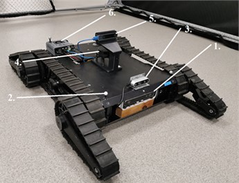
The custom navigation system hardware consists of NVIDIA Jetson Xavier NX board, Zed RGBD camera, Intel RealSense T265, D435 and RPLIDAR A1 laser scanner. As depicted in Fig. 1, the NVIDIA Jetson Xavier NX board is the main controlling unit of the system, all the algorithms related to simultaneous localisation and mapping (SLAM), perception, path planning and motion control is processed on this board. The Jetson board is connected to an Ethernet switch on the robot which is further connected to the PM55005-JV2 motion controller of the robot. Zed RGBD camera, Intel RealSense T265, D435 and RPLIDAR is attached to Jetson via USB 3.0. The additional hardware components are fixed on the robot chassis by 3D printed mounts. Dampers were added to the 3D printed mount of the camera for stabilization. Custom hardware architecture and its integration are represented in Fig. 1, and Fig. 2.
Fig. 1Custom hardware architecture
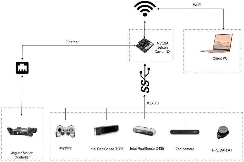
Fig. 2Jaguar platform modified with custom hardware elements: 1 – Zed camera; 2 – Reflective marker; 3 – Intel RealSense D435; 4 – RPLIDAR A1; 5 – Intel RealSense T265; 6 – NVIDIA Jetson Xavier NX
3.2. Software description
Since the quality of odometry data greatly affects the overall performance of the robot in any given task, we are giving a brief description of the whole autonomous system and how different VO methods are tested as a part of it. The robot’s autonomous navigation system and test scenarios are fully developed using Robot Operating System (ROS) Melodic version and ROS wrappers available for different VO algorithms and vendor-specific hardware used.
Fig. 3Autonomous navigation system software architecture
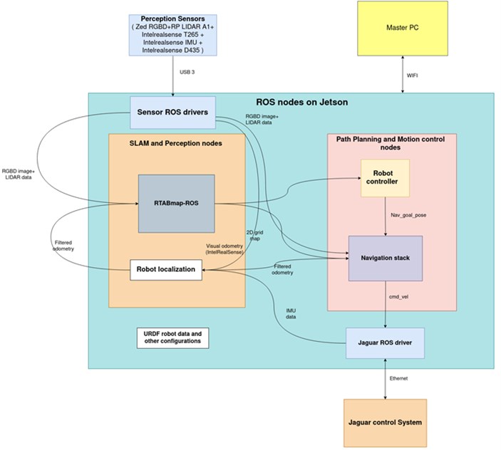
The autonomous system consists of two main modules, namely: SLAM and Planning, as shown in Fig. 3. The localization part of SLAM depends on the chosen VO method in testing, rgbd_odometry from RTAB-Map. package and vendor-specific packages: zed_ros_wrapper, realsense2_camera which are fused with IMU data from Intel RealSense T265 camera, then fed to mapping and planning modules. The mapping part of SLAM is done using the RTAB-Map package for all the test scenarios with optimized parameters to limit computational power consumption.
For planning, a navigation stack is used which utilizes a set of planners (teb_planner as a local planner and a global planner based on Djikstra algorithm) to plan for a commanded goal point while avoiding obstacles and a set of recovery behaviours activated if the robot is trapped, facing kidnapping problem or getting poor odometry data. The computed plan is followed by executing velocity commands of navigation stack using vendor-specific drrobot package for low-level motor control.
The effect of different VO methods data on generated maps quality and planning execution performance is discussed in the upcoming sections as well as their ease of integration with the rest of autonomous system modules.
4. Tests of visual-inertial odometry algorithms
The tests were conducted indoors in a controlled 6×6 m test arena, on a flat and non-slippery surface. As shown in Fig. 4, the walls of the test arena are covered with black cloth to make the scene more challenging for the visual odometry algorithms and to adjust the number of visual elements in the robot’s field of view. There are several objects such as boxes, chairs etc. placed in a random manner inside the test arena as static visual elements. While performing the tests all the VO methods were running in parallel, to ensure that all the algorithms were exposed to the same test environment.
Fig. 4Test arena
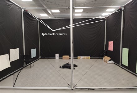
The OptiTrack camera system was used for ground truth estimation. Eight Prime-13 cameras were placed on every pillar of the test arena, which can detect reflective markers placed on the robot. As illustrated in Fig. 2. four reflective markers were used on the top of the robot for estimating position in 6 degrees of freedom (DOF). The pivot point (centroid) calculated through the markers was adjusted to make the final frame parallel to the base_link frame of the robot along the z-axis. To receive data in ROS from an OptiTrack system a Motive software was running on the windows machine acting as a server. The mocap_optitrack ROS package was used to fetch the data and publish it as ROS topics.
To ensure a fair comparison between all the odometry methods, all algorithms were running in parallel and Intel RealSense T265’s IMU data was fused with other odometry approaches. For comparative analysis, the odometry topics were recorded in rosbag files and analysed as well as generated maps from RTAB-Map. The motion profiles commanded to the robot were varied from being smooth and slow to jerky and aggressive, making it more dynamic and challenging for odometry algorithms.
4.1. Zed camera odometry
Zed camera is a stereo camera that comes with two 4MP cameras which can capture 3D videos in 2K resolution with low light making it suitable to work in challenging environments. The camera does not have visual Simultaneous localization and mapping (V-SLAM) algorithms running on onboard Vision Processing Unit (VPU), but it comes with various tools out of which zed SDK is used. The SDK provides a variety of information from which RGB and depth images are used by the rtabmap_ros package for real-time 3D mapping and 3D scene generation in the form of a point cloud. It also provides stereo visual odometry. For acquiring the maximum update frequency rate, the image acquisition was done at a resolution of 672×376. The integration of zed SDK with ROS is done with the zed_ros_wrapper package. The odometry topic from the zed_wrapper package was fused with T265 IMU data using an instance of robot_localisation ROS package. The IMU data is first filtered using the imu_complimentary_filter ROS package and then fed to robot localization. The obtained 2D trajectory is presented in Fig. 5(a) as the red line and the black line is estimated by the OptiTrack camera system as the ground truth.
Fig. 5Trajectories compared to ground truth
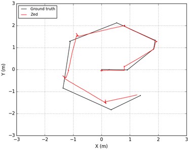
a) Zed
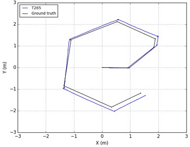
b) Intel RealSense T265
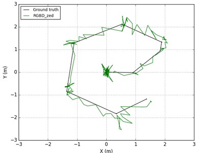
c) Zed RTAB-Map RGBD
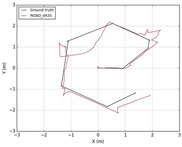
d) Intel RealSense D435 RTAB-Map RGBD
4.2. Intel RealSense T265 odometry
Intel RealSense T265 is a tracking camera that comes with two fisheye lenses and a tracking camera with a resolution of 848×800. It features V-SLAM algorithms that run onboard as an Intel Movidius Myriad 2 VPU for robotics, drone, and augmented reality uses. As the V-SLAM algorithms on the T265 run directly on the VPU, there is very little latency and very little power usage. The T265 has a closed-loop drift of less than 1 % (under intended use conditions). It also creates only a 6ms lag between movement and reflection of movement in the stance, which is fast enough for robotic applications. Intel RealSense2_camera package is used for the integration of V-SLAM algorithms running on camera with ROS. The obtained 2D trajectory is presented in Fig. 5(b) as the blue line and the black line is estimated by the OptiTrack camera system as the ground truth.
4.3. Zed camera and Intel RealSense D435 camera RTAB-Map RGBD odometry
RTAB-Map is distributed as an open-source library since 2013. To deal with the large-scale and long-term online operation, RTAB-Map began as an appearance-based loop closure detection technique with memory management [40]. RTAB-Map offers both visual and lidar SLAM, allowing users to construct and compare several 3D and 2D solutions for a variety of applications using different robots and sensors in a single package. It creates maps by combining depth images with RGB photos. The graph is built here, with each node including RBG and depth photos, as well as odometry poses. The transformations between each node are represented by the links. RTAB-Map also provides visual and laser odometry data using LIDAR, stereo or RGBD cameras. In the tests, we have used two instances of RGBD odometry nodelets from the RTAB map. One for zed camera and another for Intel RealSense D435 respectively. The nodelet also allows fusing the IMU topic, therefore Intel RealSense T265 IMU was fused with both the instances of the RGBD_odometry nodelets. The 2D trajectories estimated from both cameras is presented in Fig. 5(c) and Fig. 5(d) as green and brown lines respectively and the black line is estimated by the OptiTrack camera system as the ground truth.
5. Comparative analysis
5.1. Analysis of trajectories
In this section, a comparative analysis of all the trajectories estimated by different odometry algorithms is provided. The error estimation was done using maximum and average deviation. The formulae used for calculating maximum and average error deviation is shown in Eqs. (1) and (2) respectively. Where , are the coordinates of the ground truth trajectory from the OptiTrack system and , are the coordinates of computed trajectory at time :
Fig. 6Combined comparison of trajectories
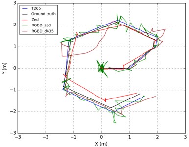
Even though from Fig. 6, we can observe that all the trajectories estimated from different odometry sources are near to each other in terms of scale, the Intel RealSense T265 as depicted in Table 1 has shown the least error in the odometry with a smooth trajectory as compared to the others. Zed odometry also has shown good results in orientation despite the scale of the trajectory being smaller than Intel RealSense T265 and the ground truth. RGBD odometry from RTAB-Map generally shows a deviation in the beginning but later when compared the overall trajectory showed results near to the ground truth trajectory. RTAB-Map RGBD odometry calculated from zed camera data is noisier as compared to the RTAB-Map RGBD odometry from Intel RealSense D435. Odometry from D435 is not as noisy as the one from the zed camera despite it having some pose jumps. Zed_wrapper, RTAB-Map RGBD and Intel RealSense D435 nodes were processed on the Jetson using their SDK’s respectively unlike Intel RealSense T265 which uses its on-board VPU for the processing which makes it much faster than the compared solutions. In terms of camera lens types, Intel RealSense is featured with two fish-eye lenses which allow it to detect more features in every captured frame as compared with the zed camera and Intel RealSense D435.
Table 1Comparison of trajectories estimated by different visual-inertial odometry algorithms
Visual Odometry | Camera | Average deviation, (m) | Maximum deviation, (m) |
Zed | Zed camera | 0.19 | 0.55 |
Intel RealSense T265 | Intel RealSense T265 | 0.08 | 0.29 |
RTAB-Map RGBD odom | Zed camera | 0.13 | 0.73 |
RTAB-Map RGBD odom | Intel RealSense D435 | 0.30 | 1.19 |
5.2. Map analysis
As described in Section 2, RTAB-Map is used as the mapping library throughout all the tests of different VO methods. It uses a graph-based approach based on global Bayesian loop closure detection. A new constraint is introduced to the map graph once a loop closure is detected, then the whole graph is optimized to minimize errors. RTAB-Map is a good candidate for our tests as odometry data plays a crucial role in the quality of generated dense 3D maps and the validity of detected loop closures. which highlights the importance of comparing the effect of different odometry methods on map generation as discussed below.
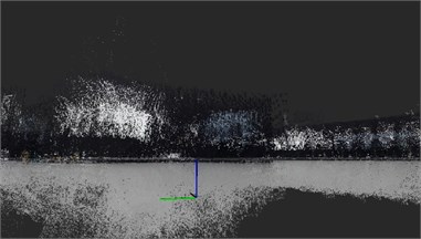
Since the Intel RealSense T265 gave the best and least noisy odometry data with a high rate, the quality of generated dense map shown in Fig. 7(a) is the highest with low dispersion and a low number of outliers and with the best definition of obstacles and their geometry. Odometry from the zed camera wrapper as shown in Fig. 7(b) resulted also in good quality dense map generation, but with higher dispersion than the Intel RealSense T265. Obstacles are relatively well defined with little inflation of their geometry, which limits the robot from navigating through narrow corridors, but the obstacle dimensions can be refined with multiple mapping iterations. Maps generated while using rgbd_odometry from zed camera and Intel RealSense D435 illustrated in Fig. 7(c) and Fig. 7(d) respectively are very dispersed because of noisy odometry data that accumulates error and drifts from the real position of the robot. In the case of the zed camera test, it was mainly because of orientation estimation errors unlike for Intel RealSense D435 which was because of translation estimation errors. In both cases, the resulting map cannot be used and causes the navigation system to fail.
It is noted also since the movement of the Jaguar robot produces internal vibrations that affect odometry estimation as well as dense 3D map generation. All the generated maps suffer from dispersion to some extent, which was acceptable and nearly neglected in the case of using Intel RealSense T265 or Zed camera wrapper as the source of odometry.
Experimental tests made in this section were related to the SLAM module for the autonomous navigation system. To be implemented on a fully autonomous tracked robot, the odometry should also be tested with the navigation module to study the effect of dynamic velocities on the odometry. The path planning module (navigation stack) works effectively with high-quality odometry data but fails often if the odometry data is noisy and puts the robot into a recovery behaviour state. Therefore, Intel RealSense T265 was chosen to conduct further experiments.
Fig. 7RTAB-Map dense map from different odometry sources
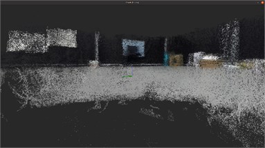
a) Intel RealSenseT265
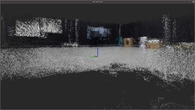
b) Zed
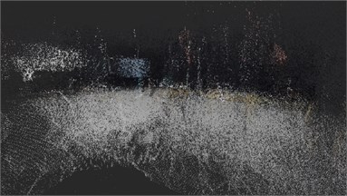
c) Intel RealSense D435 RTAB-Map RGBD
d) Zed RTAB-Map RGBD
6. Evaluation of Intel RealSense T265 accuracy with different motion profiles
The confidence or trust of odometry data estimation can vary with different motion profiles, therefore, to increase the confidence, the robot must execute jerky motion so the VO algorithm can detect big differences between visual features in different image frames and calculate accurate odometry data. In the following tests, three acceleration thresholds were tested with two fixed velocity thresholds under which the system gave results near to the ground truth. The maximum acceleration was limited between 0.3 m/s2 and 0.7 m/s2 as the V-SLAM algorithm running on Intel RealSense T265 gave poor linear vector data when the accelerations were below 0.3 m/s2 and caused SLAM errors due to inbound vibrations when accelerations were above 0.7 m/s2. In the experiments, the average and maximum deviations were calculated from measured data and shown in Table 2.
Table 2Evaluation of Intel RealSense odometry
Test No. | Max velocity, (m/s) | Max acceleration, (m/s2) | Average deviation, (m) | Maximum deviation, (m) |
1. | 0.5 | 0.3 | 0.6 | 3.82 |
2. | 0.5 | 0.5 | 1.08 | 2.91 |
3. | 0.5 | 0.7 | 0.14 | 0.31 |
4. | 1.0 | 0.3 | 0.29 | 2.09 |
5. | 1.0 | 0.5 | 0.46 | 1.37 |
6. | 1.0 | 0.7 | 0.12 | 0.38 |
It is noticed from Tests No. 3. and 6. that when the robot is executing jerky motion because of higher acceleration, the confidence in odometry data increases resulting in lower average and maximum deviation from the ground truth. In contrast to Tests No. 1. and 4 where the robot’s motion was smooth, which increased the average and maximum deviation from the ground truth. When jerk is bounded as in Tests No. 2. and 5., the quality of odometry data is not guaranteed as the confidence increases only if the robot is moving with maximum velocity.
From the accuracy evaluation tests, we can conclude that when the robot moves with higher acceleration and velocity, the VO algorithm will be more accurate, and when the robot is slow, the VO will suffer from detecting small changes of visual features between different frames. However, since it is not always possible to move with high acceleration and velocity, we developed an “odometry recovery” behaviour, that is executed every-time odometry data becomes uncertain. The robot will move its flippers to push on the ground at which the base will move up, then move the flippers up again so the base rests on the ground. When the robot executes this behaviour fast enough (without moving in or directions), the accuracy of odometry data increases again.
7. Conclusions
In this article, a ROS-based autonomous navigation system for a tracked mobile robot was proposed, on which we have integrated and benchmarked the performance of different visual-inertial odometry methods providing a comparative analysis of odometry data and generated maps. Visual odometry on tracked robots is now essential but challenging as the robot’s motion results in bounded internal vibrations, and it is expected to navigate in a complex environment. We tested Intel RealSense T265, Zed camera and rgbd_odometry from RTAB-Map using Intel RealSense D435 and Zed camera, then the best method was evaluated with different motion profiles showing the effect of the robot’s velocity and acceleration on the accuracy of VO.
Obtained results prove that although different algorithms are available for visual odometry, the estimation is still a non-trivial task. Intel RealSense T265 showed the best performance but only if the robot’s motion is fast enough to increase the confidence in odometry estimation. Zed camera had a good performance while its computed trajectory scale was less than the ground truth. rgbd_odometry from RTAB-Map gave noisy odometry data on both Zed and Intel RealSense D435 and tuning its parameters was a non-trivial task. An odometry recovery routine where the robot executes in-place motion or moves around till it detects a loop closure to increase confidence in visual odometry estimation is needed when the algorithm fails to provide accurate data. Also using a tracking camera with lidar and having the ability to recover from poor odometry information, extends the robot capabilities to navigate safely in environments with limited visual features. The proposed architecture maximizes the modularity of the system as an adaption to changes in the environment can be also done by a respective hardware component change. Which has minimal impact on the other components of the system, however one should consider how different hardware and software elements contributes to the overall performance of the system.
Our future work includes adding a robot arm to the Jaguar robot and adapting the autonomous navigation system for mobile manipulation tasks. In that matter, the system capabilities will be extended to autonomously detect and estimate the pose of the objects of interest. Furthermore, the overall robustness of the developed system will be evaluated in an outdoor environment with more challenging terrain and lighting conditions.
References
-
K. Cresswell, S. Cunningham-Burley, and A. Sheikh, “Health Care Robotics: Qualitative exploration of key challenges and future directions,” Journal of Medical Internet Research, Vol. 20, No. 7, p. e10410, Jul. 2018, https://doi.org/10.2196/10410
-
G. Ren, T. Lin, Y. Ying, G. Chowdhary, and K. C. Ting, “Agricultural robotics research applicable to poultry production: A Review,” Computers and Electronics in Agriculture, Vol. 169, p. 105216, Feb. 2020, https://doi.org/10.1016/j.compag.2020.105216
-
F. Bader and S. Rahimifard, “A methodology for the selection of industrial robots in food handling,” Innovative Food Science and Emerging Technologies, Vol. 64, p. 102379, Aug. 2020, https://doi.org/10.1016/j.ifset.2020.102379
-
J. Arents, M. Greitans, and B. Lesser, “Construction of a smart vision-guided robot system for manipulation in a dynamic environment,” in Artificial Intelligence for Digitising Industry, 2021.
-
G. Urlini, J. Arents, and A. Latella, “AI in industrial machinery,” in Artificial Intelligence for Digitising Industry, 2021.
-
P. Szegedi, P. Koronváry, and B. Békési, “The use of robots in military operations,” Scientific Research and Education in the Air Force, Vol. 19, No. 1, pp. 221–230, Jul. 2017, https://doi.org/10.19062/2247-3173.2017.19.1.25
-
J. Arents, V. Abolins, J. Judvaitis, O. Vismanis, A. Oraby, and K. Ozols, “Human-robot collaboration trends and safety aspects: a systematic review,” Journal of Sensor and Actuator Networks, Vol. 10, No. 3, p. 48, Jul. 2021, https://doi.org/10.3390/jsan10030048
-
J. Arents and M. Greitans, “Smart industrial robot control trends, challenges and opportunities within manufacturing,” Applied Sciences, Vol. 12, No. 2, p. 937, Jan. 2022, https://doi.org/10.3390/app12020937
-
F. Gul, W. Rahiman, and S. S. Nazli Alhady, “A comprehensive study for robot navigation techniques,” Cogent Engineering, Vol. 6, No. 1, p. 16320, Jan. 2019, https://doi.org/10.1080/23311916.2019.1632046
-
“Executive summary world robotics 2021 – Service robots.”. https://ifr.org/img/worldrobotics/executive_summary_wr_service_robots_2021.pdf (accessed 2021).
-
M. Cardona, F. Cortez, A. Palacios, and K. Cerros, “Mobile robots application against Covid-19 pandemic,” in 2020 IEEE Andescon, pp. 1–5, Oct. 2020, https://doi.org/10.1109/andescon50619.2020.9272072
-
F. Rubio, F. Valero, and C. Llopis-Albert, “A review of mobile robots: concepts, methods, theoretical framework, and applications,” International Journal of Advanced Robotic Systems, Vol. 16, No. 2, p. 172988141983959, Mar. 2019, https://doi.org/10.1177/1729881419839596
-
G. Fragapane, R. de Koster, F. Sgarbossa, and J. O. Strandhagen, “Planning and control of autonomous mobile robots for intralogistics: literature review and research agenda,” European Journal of Operational Research, Vol. 294, No. 2, pp. 405–426, Oct. 2021, https://doi.org/10.1016/j.ejor.2021.01.019
-
S. Habibian et al., “Design and implementation of a maxi-sized mobile robot (Karo) for rescue missions,” Robomech Journal, Vol. 8, No. 1, Dec. 2021, https://doi.org/10.1186/s40648-020-00188-9
-
P. K. Panigrahi and S. K. Bisoy, “Localization strategies for autonomous mobile robots: a review,” Journal of King Saud University – Computer and Information Sciences, Mar. 2021, https://doi.org/10.1016/j.jksuci.2021.02.015
-
“Jaguar V4 Mobile Robotic Platform.”. http://jaguar.drrobot.com/specification_v4.asp (accessed 2021).
-
G. Baker et al., “ATLAS – Urban Search and rescue robot,” Warwick Mobile Robotics, 2017.
-
P. Ben-Tzvi and W. Saab, “A hybrid tracked-wheeled multi-directional mobile robot,” Journal of Mechanisms and Robotics, Vol. 11, No. 4, Aug. 2019, https://doi.org/10.1115/1.4043599
-
R. Gonzalez, F. Rodriguez, J. L. Guzman, and M. Berenguel, “Localization and control of tracked mobile robots under slip conditions,” in 2009 IEEE International Conference on Mechatronics, 2009, https://doi.org/10.1109/icmech.2009.4957141
-
A. H. Adiwahono, B. Saputra, T. W. Chang, and Z. X. Yong, “Autonomous stair identification, climbing, and descending for tracked robots,” in 2014 13th International Conference on Control Automation Robotics and Vision (ICARCV), Dec. 2014, https://doi.org/10.1109/icarcv.2014.7064278
-
M. M. Ejaz, T. B. Tang, and C.-K. Lu, “Vision-based autonomous navigation approach for a tracked robot using deep reinforcement learning,” IEEE Sensors Journal, Vol. 21, No. 2, pp. 2230–2240, Jan. 2021, https://doi.org/10.1109/jsen.2020.3016299
-
Z. Li, X. Jing, B. Sun, and J. Yu, “Autonomous Navigation of a tracked mobile robot with novel passive bio-inspired suspension,” IEEE/ASME Transactions on Mechatronics, Vol. 25, No. 6, pp. 2633–2644, Dec. 2020, https://doi.org/10.1109/tmech.2020.2987004
-
S. Shentu, F. Xie, X.-J. Liu, and Z. Gong, “Motion control and trajectory planning for obstacle avoidance of the mobile parallel robot driven by three tracked vehicles,” Robotica, Vol. 39, No. 6, pp. 1037–1050, Jun. 2021, https://doi.org/10.1017/s0263574720000880
-
T. Sasaki and T. Fujita, “Gap traversing motion via a hexapod tracked mobile robot based on gap width detection,” Journal of Robotics and Mechatronics, Vol. 33, No. 3, pp. 665–675, Jun. 2021, https://doi.org/10.20965/jrm.2021.p0665
-
L. C. Yeh and H. Nugroho, “Design of hardware-in-the-loop simulation approach for slip-compensated odometry tracked mobile robot platform,” in 2021 8th International Conference on Computer and Communication Engineering (ICCCE), Jun. 2021, https://doi.org/10.1109/iccce50029.2021.9467181
-
G. Rigatos, “A nonlinear optimal control approach for tracked mobile Robots,” Journal of Systems Science and Complexity, Vol. 34, No. 4, pp. 1279–1300, Aug. 2021, https://doi.org/10.1007/s11424-021-0036-1
-
S. Fu, C. Zhang, W. Zhang, and X. Niu, “Design and simulation of tracked mobile robot path planning,” in 2021 IEEE 4th International Conference on Big Data and Artificial Intelligence (BDAI), Jul. 2021, https://doi.org/10.1109/bdai52447.2021.9515251
-
D. Valiente García, L. Fernández Rojo, A. Gil Aparicio, L. Payá Castelló, and O. Reinoso García, “Visual odometry through appearance – and feature-based method with omnidirectional images,” Journal of Robotics, Vol. 2012, pp. 1–13, 2012, https://doi.org/10.1155/2012/797063
-
D. G. Lowe, “Distinctive image features from scale-invariant keypoints,” International Journal of Computer Vision, Vol. 60, No. 2, pp. 91–110, Nov. 2004, https://doi.org/10.1023/b:visi.0000029664.99615.94
-
R. Gonzalez, F. Rodriguez, J. L. Guzman, C. Pradalier, and R. Siegwart, “Combined visual odometry and visual compass for off-road mobile robots localization,” Robotica, Vol. 30, No. 6, pp. 865–878, Oct. 2012, https://doi.org/10.1017/s026357471100110x
-
D. Scaramuzza and R. Siegwart, “Appearance-guided monocular omnidirectional visual odometry for outdoor ground vehicles,” IEEE Transactions on Robotics, Vol. 24, No. 5, pp. 1015–1026, Oct. 2008, https://doi.org/10.1109/tro.2008.2004490
-
D. Scaramuzza and F. Fraundorfer, “Visual odometry [tutorial],” IEEE Robotics and Automation Magazine, Vol. 18, No. 4, pp. 80–92, Dec. 2011, https://doi.org/10.1109/mra.2011.943233
-
J. Campbell, R. Sukthankar, I. Nourbakhsh, and A. Pahwa, “A robust visual odometry and precipice detection system using consumer-grade monocular vision,” in Proceedings of the 2005 IEEE International Conference on Robotics and Automation, 2005, https://doi.org/10.1109/robot.2005.1570639
-
C. Wang, C. Zhao, and J. Yang, “Monocular odometry in country roads based on phase‐derived optical flow and 4‐Dof Ego‐Motion model,” Industrial Robot: An International Journal, Vol. 38, No. 5, pp. 509–520, Aug. 2011, https://doi.org/10.1108/01439911111154081
-
D. Nistér, O. Naroditsky, and J. Bergen, “Visual odometry for ground vehicle applications,” Journal of Field Robotics, Vol. 23, No. 1, pp. 3–20, Jan. 2006, https://doi.org/10.1002/rob.20103
-
M. Sharifi, X. Chen, and C. G. Pretty, “Experimental study on using visual odometry for navigation in outdoor GPS-denied environments,” in 2016 12th IEEE/ASME International Conference on Mechatronic and Embedded Systems and Applications (MESA), Aug. 2016, https://doi.org/10.1109/mesa.2016.7587182
-
N. Ragot, R. Khemmar, A. Pokala, R. Rossi, and J.-Y. Ertaud, “Benchmark of visual slam algorithms: Orb-slam2 vs RTAB-Map*,” in 2019 Eighth International Conference on Emerging Security Technologies (EST), Jul. 2019, https://doi.org/10.1109/est.2019.8806213
-
A. Alapetite, Z. Wang, J. P. Hansen, M. Zajączkowski, and M. Patalan, “Comparison of three off-the-shelf visual odometry systems,” Robotics, Vol. 9, No. 3, p. 56, Jul. 2020, https://doi.org/10.3390/robotics9030056
-
I. Z. Ibragimov and I. M. Afanasyev, “Comparison of ROS-based visual slam methods in homogeneous indoor environment,” in 2017 14th Workshop on Positioning, Navigation and Communications (WPNC), Oct. 2017, https://doi.org/10.1109/wpnc.2017.8250081
-
M. Labbe and F. Michaud, “Appearance-based loop closure detection for online large-scale and long-term operation,” IEEE Transactions on Robotics, Vol. 29, No. 3, pp. 734–745, Jun. 2013, https://doi.org/10.1109/tro.2013.2242375
About this article

This work was partially funded by the Electronic Components and Systems for European Leadership Joint Undertaking (ECSEL JU) in collaboration with the European Union’s H2020 Framework Programme under grant agreement No. 826600.
