Abstract
Abrasive flow machining (AFM) technology can achieve precision machining finish for processing special curved pipe parts. In order to study the processing effect of abrasive flow machining for special curved pipe parts, polygonal spiral curved pipe is taken as the research object. The large eddy simulation (LES) method is used to simulate and numerically analyze the processing of polygonal spiral curved pipe. The static pressure cloud diagram, turbulence kinetic energy cloud diagram and turbulence intensity cloud diagram under different inlet pressures are obtained to analyze the influence of inlet pressure on the workpiece processed by abrasive flow. The fluid trace diagrams are obtained at the inlet and outlet of the workpiece, and the vortex changes of the fluid inside the workpiece are analyzed. The mechanism of vortex variation is revealed, which provides theoretical support for practical processing in the future.
Highlights
- The large eddy simulation method is used to study the polygonal spiral curved pipe machining by abrasive flow.
- The effects of inlet pressure on static pressure, turbine kinetic energy and turbulence intensity were studied.
- The change of abrasive in the polygonal spiral curved pipe is obtained by analyzing the fluid trace of the inlet and outlet.
1. Introduction
Abrasive flow machining (AFM) is a kind of processing technology that can mix abrasive with certain concentration and flow through the workpiece surface under certain inlet pressure to finish deburring, fillet and stress relief which are difficult or impossible for other processes [1, 2]. Spiral curved tube has an important and wide range of applications in the manufacturing industry. Among them, the most well-known application is the rifling pipe called the soul of firearms in the military field. Therefore, it is particularly important to study the processing accuracy and quality of polygonal spiral curved pipes. Ranjan P. et al. conducted a molecular dynamics simulation to investigate the material removal phenomenon of chemo-mechanical magneto-rheological finishing (CMMRF) process. Effects of process parameters like abrasive particles, depth of penetration and initial surface condition on finishing force, potential energy and material removal at atomic scale were investigated. It was observed that the type of abrasive particle was one of the important parameters to produce atomically smooth surface [3]. Bianco V. et al. investigated a double-circuit Ranque-Hilsch vortex tube using a fully three-dimensional numerical model of the turbulent compressible air flow. The main purpose of the paper was to perform a detailed analysis of the thermal and flow patterns obtained with RSM-LRR and LES turbulence models. It was found that the LES turbulence model represented the qualitative turbulence of the flow better than the RSM-LRR model [4]. Zhao et al. proposed a new method of soft abrasive rotary flow (SARF) polishing to solve the problem of ultra-precision polishing of K9 optical glass. The optimal level combination of the SARF polishing parameters was conducted by the Taguchi experiment [5]. Li et al. used molecular dynamics methods to simulate the micro-cutting of iron-carbon alloys with silicon carbide particles to explore the evolution mechanism of the subsurface defect structure of iron-carbon alloy workpieces in the abrasive flow machining process. The distribution and evolution of defect structure during micro-cutting were analyzed, and the removal mechanism of workpiece material during micro-cutting was revealed [6].
2. Large eddy simulation theory
The solid-liquid two-phase polishing fluid is mainly incompressible, so it is necessary to use the continuity equation. The continuity equation for the three-dimensional unsteady flow is:
where is the density of the fluid, is the time. Use , , to represent the spatial rectangular coordinate system, and use , , as the velocity components.
For the large eddy simulation of incompressible turbulence, it is assumed that the filtering process and the differential operation are interchangeable [7]. The equation after filtering is:
where is velocity, is time, is pressure, is viscosity coefficient, and , and represent space coordinates, and respectively.
3. Numerical analysis with large eddy simulation
3.1. Model construction and meshing of polygonal spiral curved pipe workpiece
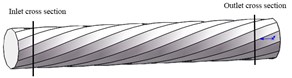
In order to carry out large eddy simulation numerical analysis and research on the polygonal spiral curved pipe, it is necessary to establish a workpiece model. The selected polygonal spiral curved pipe is regular dodecagonal with an outer diameter of 15 mm, and the diameter of the circumscribed circle of the inner diameter is 5.56 m. The established models are shown in Fig. 1.
Fig. 1The model of polygonal spiral curved pipe
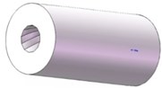
a) Three-dimensional model diagram
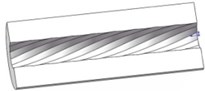
b) Axial section diagram
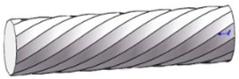
c) Inner channel model diagram
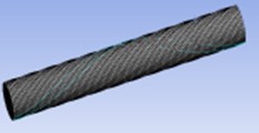
The grid quality of the inner channel model required for large eddy simulation is relatively high, and the meshing diagram is shown in Fig. 2.
The inner channel model is to fill and wrap the inner channel of the three-dimensional model, which is in line with the actual situation. The quality of the grid determines the accuracy of the calculation results, so it is necessary to check the quality of the divided grid. After checking, the area and volume of the grid are not appearing negative values, and all of them are between 0 and 1. Therefore, the mesh quality of the polygonal spiral curved pipe model is qualified.
Fig. 2Inner channel meshing diagram
3.2. Selection of boundary conditions for large eddy simulation
Abrasive flow machining belongs to the category of multiphase flow. When performing numerical analysis, it is necessary to set the flow field parameters according to the actual processing conditions. For the solid-liquid two-phase abrasive flow processing the polygonal spiral curved pipe, it is necessary to select the Mixture model based on the double-precision parallel solver. The solid phase is set to silicon carbide with a density of 3170 kg/m3, and the liquid phase is set to oil with a density of 1260 kg/m3.
This paper studies the abrasive flow machining performance under different inlet pressure conditions, so the inlet boundary condition is set as the pressure inlet boundary condition. According to the actual situation of abrasive flow machining, it is difficult to measure the speed and pressure of abrasive particles flowing out of the workpiece. The outlet end is connected with the outside world, so the outlet boundary condition is set as free outlet, which makes the large eddy simulation more practical.
3.3. Numerical simulation analysis of the influence of different pressure inlet boundary conditions on abrasive flow machining
According to the actual situation, the inlet pressure is set to 3 MPa, 4 MPa, 5 MPa, 6 MPa, and the outlet pressure is set to 0 MPa. Based on the research experience of our laboratory and calculation, the volume fraction of abrasive is set to 30 %. After the parameter setting is completed, the cloud diagrams of different evaluation criteria can be obtained for analysis. In order to better observe and analyze the fluid in the flow channel of the workpiece, the axial section of the workpiece is selected as the analysis part.
3.3.1. Numerical analysis of static pressure under different inlet pressures
The static pressure cloud diagrams of the polygonal spiral curved pipe processed by the abrasive particle flow under different inlet pressure conditions are shown in Fig. 3.
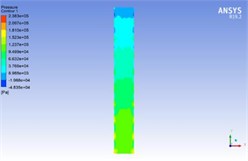
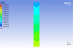
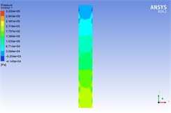
Fig. 3The static pressure cloud diagrams under different inlet pressures

a) Inlet pressure at 3 MPa
b) Inlet pressure at 4 MPa
c) Inlet pressure at 5 MPa
d) Inlet pressure at 6 MPa
In Fig. 3, the upper side is the outlet and the lower side is the inlet. Under the same inlet pressure, the static pressure presents an obvious step-like distribution trend in the flow channel. The static pressure is the largest at the inlet and the minimum at the outlet. This is because the abrasive enters the flow channel after a violent collision with the wall at the inlet, and the collision with the wall gradually decreases, so the static state is gradually smaller and reaches the minimum at the outlet. As the inlet pressure increases from 3 MPa to 6 MPa, the contact frequency between the abrasive particles and the wall increases, and the static pressure increases accordingly. Reasonably increasing the inlet pressure can increase the static pressure value and improve the processing effect.
3.3.2. Numerical analysis of turbulence kinetic energy under different pressures
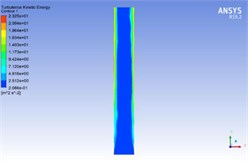
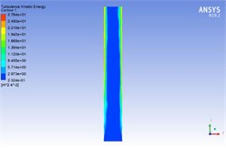
Turbulence kinetic energy is the most important characteristic quantity to describe the characteristics of turbulent motion. The turbulence kinetic energy cloud diagrams are shown in Fig. 4.
Fig. 4The turbulence kinetic energy cloud diagrams under different inlet pressures
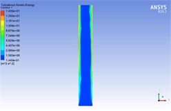
a) Inlet pressure at 3 MPa

b) Inlet pressure at 3 MPa
c) Inlet pressure at 3 MPa
d) Inlet pressure at 3 MPa
In Fig. 4, the upper side is the inlet and the lower side is the outlet. It can be seen from Fig. 4 that under the same inlet pressure, the value of turbulence kinetic energy in the flow channel is the smallest and the distribution hardly changes. Because the wall of the flow channel has a spiral curved structure, the abrasive particles exchange energy violently with the wall surface, and the turbulence kinetic energy on the wall of the flow channel is relatively large. The speed and direction of the abrasive particles change greatly after contact with the wall, and the energy of particles rebounding back into the flow channel is lost. Then the turbulent flow energy is drastically reduced. As the inlet pressure increases from 3 MPa to 6 MPa, the turbulent flow energy increases accordingly. With the increase of inlet pressure, the energy carried by abrasive particles increases and the turbulence kinetic energy in all areas of the flow channel increases, which is conducive to the processing of the workpiece.
3.3.3. Numerical analysis of turbulence intensity under different pressures
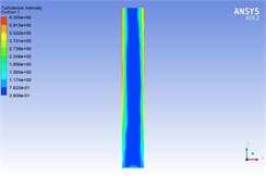
Turbulence intensity is the most important characteristic to describe the characteristics of turbulent motion. The turbulence intensity cloud diagrams are shown in Fig. 5.
In Fig. 5, the upper side is the outlet and the lower side is the inlet. It can be seen from Fig. 5 that the turbulence intensity near the wall is higher than the turbulence intensity in the channel. Under the same inlet pressure, the turbulence intensity does not change in the channel. With the flow of abrasive, the intensity of turbulence near the wall shows a decreasing trend. After the particles rebound back to the channel, the energy disappears greatly and the turbulence intensity decreases greatly. The energy is gradually lost in the process of abrasive flow, so the turbulence intensity at the outlet is the lowest. As the inlet pressure increases from 3 MPa to 6 MPa, the turbulence intensity increases, making the flow of abrasive particles more disorderly. With the increase of the disorder, the effect of abrasive particles on the wall is stronger and the surface quality is better.
Fig. 5The turbulence intensity cloud diagrams under different inlet pressures
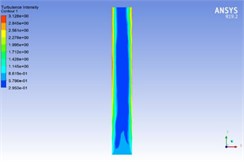
a) Inlet pressure at 3 MPa

b) Inlet pressure at 4 MPa

c) Inlet pressure at 5 MPa
d) Inlet pressure at 6 MPa
3.3.4. Analysis of fluid trace diagram
Abrasive flow machining polygonal spiral curved pipe will form large and small vortices in the flow channel, which is an important factor for better processing of the workpiece. By analyzing the fluid trace diagram at the inlet and outlet positions, the fluid movement inside the workpiece can be obtained more intuitively. According to the calculation and actual processing conditions, the volume fraction of abrasive is set to 30 %, and the inlet pressure is selected to 4 MPa. The section positions and fluid trace diagrams at inlet and outlet are shown in Fig. 6.
Fig. 6The section positions and fluid trace diagrams at inlet and outlet
a) Section positions at inlet and outlet
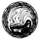
b) Fluid trace diagram at inlet
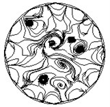
c) Fluid trace diagram at outlet
According to the fluid trace diagram in Fig. 6, when the abrasive particles just enter the pipe, a large part of the abrasive particles move around the inner channel wall of the workpiece, and there is a large vortex on one side of the pipe. With the flow of abrasive particles, the abrasive particles gradually disperse after colliding with the spiral curved pipe wall, and gradually form multiple small vortices in the channel. The vortices tend to weaken in the channel, and the turbulence becomes less active. The dispersion of the vortex is not conducive to the precision machining of the wall. From the previous study on the inlet pressure, it can be seen that increasing the inlet pressure can increase the energy carried by the fluid to obtain better polishing quality.
4. Conclusions
The static pressure cloud diagram, turbulence kinetic energy cloud diagram and turbulence intensity cloud diagram of polygonal spiral curved pipe machined by solid-liquid two-phase abrasive flow are studied by large eddy simulation method under the inlet pressure of 3 MPa, 4 MPa, 5 MPa and 6 MPa. The fluid trace diagram at the inlet and outlet of the pipe under the inlet pressure of 4Mpa is studied. The following conclusions are obtained:
1) By analyzing the static pressure cloud diagram, turbulence kinetic energy cloud diagram and turbulence intensity cloud diagram under different inlet pressure conditions, it can be found that as the inlet pressure increases, the values of each evaluation standard increase. The increase of static pressure can strengthen the micro-grinding effect of abrasive particles on the wall surface and improve the processing accuracy of abrasive flow machining. The increase of turbulence kinetic energy and turbulence intensity cloud diagram can improve the turbulent effect of abrasive particles in the flow channel of the workpiece and improve the processing quality and efficiency.
2) By analyzing the fluid trace diagram of the fluid in the polygonal spiral curved pipe, it can be known that as the abrasive particles flow in the channel, the vortex begins to weaken and disperse into multiple small vortices, and the processing effect shows a weakening trend. Appropriately increasing the inlet pressure can improve the static pressure, turbulence kinetic energy and turbulence intensity, thereby increasing the activity of the vortex, strengthening the abrasive particles to cut the surface of the workpiece, and improving the processing effect.
References
-
Petare C., Jain K. A critical review of past research and advances in abrasive flow finishing process. The International Journal of Advanced Manufacturing Technology, Vol. 97, Issues 1-4, 2018, p. 741-782.
-
Li Junuye, Liu Hongbo, Zhang Hongwei, et al. Numerical simulation analysis of micro-hole based on abrasive flow polishing. Vibroengineering Procedia, Vol. 22, Issue 3, 2019, p. 200-204.
-
Ranjan P., Balasubramaniam R., Jain K. Investigations into the mechanism of material removal and surface modification at atomic scale on stainless steel using molecular dynamics simulation. Philosophical Magazine, Vol. 98, Issue 16, 2018, p. 1437-1469.
-
Bianco V., Khait A., Noskov A., et al. A comparison of the application of RSM and LES turbulence models in the numerical simulation of thermal and flow patterns in a double-circuit Ranque-Hilsch vortex tube. Applied Thermal Engineering, Vol. 106, 2016, p. 1244-1256.
-
Zhao Jun, Huang Jinfeng, Wang Rui, et al. Investigation of the optimal parameters for the surface finish of K9 optical glass using a soft abrasive rotary flow polishing process. Journal of Manufacturing Processes, Vol. 49, 2020, p. 26-34.
-
Li Junye, Xie Hongcai, Meng Wenqing, et al. Evolution mechanism of subsurface defect structure in particle micro-cutting iron-carbon alloy process. Proceedings of the Institution of Mechanical Engineers Part J Journal of Engineering Tribology, Vols. 208-210, Issue 5, 2020, p. 1-14.
-
Li Junye, Su Ningning, Wei Lili, et al. Study on the surface forming mechanism of the solid-liquid two-phase grinding fluid polishing pipe based on large eddy simulation. Proceedings of the Institution of Mechanical Engineers Part B Journal of Engineering Manufacture, Vol. 233, Issue 14, 2019, p. 2505-2514.
About this article

The authors would like to thank the National Natural Science Foundation of China No. NSFC 51206011 and U1937201, Jilin Province Science and Technology Development Program of Jilin Province No. 20200301040RQ, Project of Education Department of Jilin Province No. JJKH20190541KJ, Changchun Science and Technology Program of Changchun City No. 18DY017.
