Abstract
Taking the flexible hoisting system as the research object, the transverse vibration mathematical model of the steel wire rope of the winding hoisting system is established, and the transverse vibration displacement, velocity and acceleration of the steel wire rope at 18 m away from one end of the wire rope under the sine excitation at other end is obtained through the comparison and verification of the results from the mathematical model, mechanical model and experiment. The results show that: for the length of the wire rope of 20 m, under the sine excitation at the end of amplitude of 0.002 m and frequency of 20 Hz, the transverse vibration displacement at 2 m from one end of the wire rope with length of 20 m is basically between –0.005 m and 0.005 m, the transverse vibration velocity at 2 m from one end of the wire rope is basically between –0.04 m/s and 0.04 m/s, and the transverse vibration acceleration of the wire rope is basically between –0.5 m/s2 and 0.5 m/s2. And the transverse vibration displacement decreases near the end, meanwhile the transverse vibration frequency increases with the reduction of length of vertical section of wire rope.
Highlights
- The manuscript proposed a mathematical model of transverse vibration of wire rope of flexible hoisting system under excitation at one end using the Hamilton principle and Euler equation,and then solved it by using the Galerkin discrete method.
- The manuscript proposed a simulation method to verify the effectiveness of the established mathematical model.In the simulation process,the wire rope is equivalent to a multi body system with cylinders connected by spring and dampers,and then the dynamic characterestics of cylinders can be aquired.
- The manuscript proposed a experimental test to further verify the validity of the established mathematical model.And the method is to compare the acceleration of numerical results and mathematical results.By comparison,the results are consistent with each other.
1. Introduction
During the running process of mine hoisting system, the steel wire rope has property of elasticity, so there are longitudinal vibration and transverse vibration of the steel wire rope. For longitudinal vibration, the study of its vibration can obtain the stress of the steel wire rope in the running process, and then adjust the parameters to reduce its dynamic tension, then preventing the wire rope from breaking up, and so improving the safety factor of the hoisting system. For the transverse vibration, the transverse vibration of the steel wire rope can be obtained by studying its vibration under a certain excitation, and then the transverse vibration of the steel wire rope can be reduced by adjusting the parameters, so as to prevent the problem of rope skipping and improve the operation stability of the hoisting system. Bao Jihu [1] and Kou Baofu [2] established the mechanical model of the flexible lifting system based on Hamilton principle and carried out the numerical solution. Wang Wen [3] transformed the lateral vibration partial differential equation of elevator wire rope into a variable coefficient ordinary differential equation by using the finite difference method and solved it. A. Mankowski [4] studied the internal damping characteristics in the transverse vibration of the steel wire rope of the mine hoisting system, and analyzed the influence of internal damping on the transverse vibration. Blodgett R. E. [5] studied the transverse vibration of the tail rope of the elevator lifting system, and proposed the method of introducing damper on the upper end of the wire rope for its transverse vibration control. H. M. Irvine [6] introduced the modeling, statics and dynamics of Cable in his book Cable Structures. G. Tagata [7] studied the transverse vibration of the steel wire rope driven by axial harmonics with one end fixed and the other end driven by axial harmonics. J. A. Wickert. [8] made A modal analysis of the string and beam models with typical axial motion, and obtained the relationship between their motion speed and vibration frequency. Shabana A. A. [9] specifically introduced the freedom and forced lateral vibration of strings in Vibration of Discrete and Continuous Systems. Bilbao S. [10] took the transverse vibration equation of nonlinear string as the starting point, and respectively uses the Kirchhoff carrier equation, digital waveguide equation and linear wave equation to solve it and analyzes the solution results. In this paper, the flexible hoisting system was took as the research object, the transverse vibration mathematical model of the steel wire rope of the flexible hoisting system was established, and through the comparison and verification of the solution results of the mechanical model, obtaining the transverse vibration displacement of the steel wire rope at two positions under the sine excitation at one end. The above research mainly adopts the variational method to obtain the transverse vibration equation of steel wire rope in flexible hoisting system. In this paper, Euler equation is adopted to derive the transverse vibration equation, which simplifies the derivation process. At the same time, this paper adopts the mechanical model and experimental model to verify the numerical model, which effectively verified the mathematical model, and can realize the further modification and improvement of the mathematical model, and thus provide better date support for the reasonable establishment of the mathematical model of transverse vibration of wire rope in hoisting system. The research and analysis of this paper has some reference basis for the modeling and analysis of the super deep flexible hoisting system, and has some reference and application value for the design of the super deep flexible hoisting system.
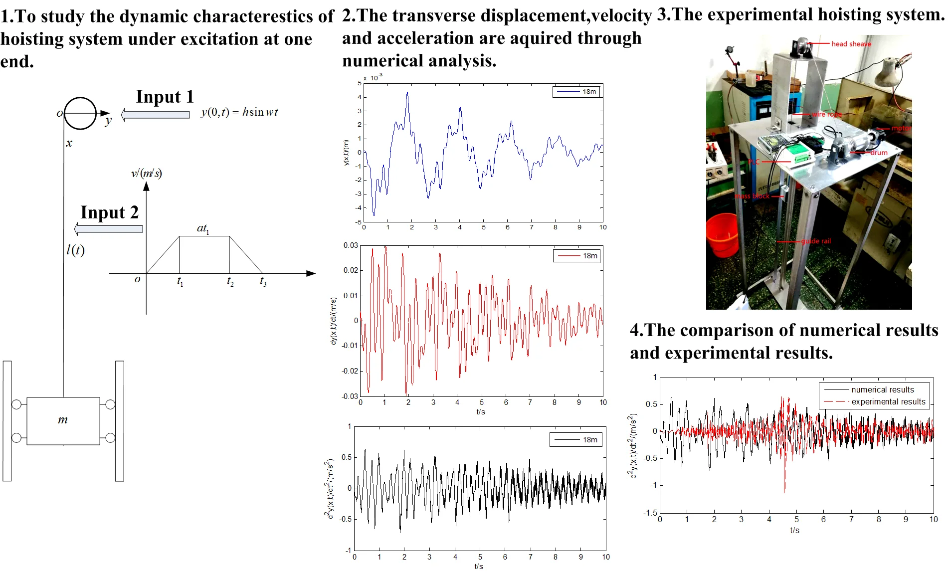
2. Establishment of mathematical model
For the flexible hoisting system, the wire rope is divided into the vertical rope, the suspended rope and the wire rope wound on the drum. Since the vertical part of the steel wire rope is directly responsible for the load bearing and lifting in hoisting system, and its length is constantly changing during the hoisting process, its transverse vibration displacement needs to be paid attention to, and its performance will directly affect the stability and safe operation of the hoisting system. Therefore, the vertical rope is selected to analyze the transverse vibration displacement, velocity and acceleration of steel wire rope of the hoisting system. Before establishing the transverse vibration model of the hoisting system, there are 2 assumptions: 1) The elasticity modulus of steel wire rope is constant during the hoisting process of the system. 2) The longitudinal vibration of the steel wire rope is ignored in order to analyze the transverse vibration of the steel wire rope. The established model of flexible hoisting system is shown in Fig. 1. In order to analyze the transverse vibration displacement of wire rope of the hoisting system, the mathematical model should be established first. The Hamilton function of steel wire rope is obtained from the energy of hoisting system, and its mathematical equation is obtained from Euler equation. Establishing the cartesian coordinate system as shown in Fig. 1. The length of the vertical rope of the hoisting system is set as , the mass of the hoisting weight is , and there are guide rails on both sides of the hoisting weight to limit its transverse vibration of load. The hoisting system has sine excitation at the wheel, the excitation amplitude is , and the excitation frequency is . The details are shown in Fig. 1.
First, find the kinetic energy of the steel wire rope with a length of . Set the speed of each point of the wire rope as . Then we can obtain the following expression:
Then, find the potential energy of the steel wire rope. The potential energy of wire rope includes stretching strain energy and bending strain energy of wire rope. The potential energy is:
Within that, and are respectively the stretching and bending stiffness of the steel wire rope, and are the stretching strain and the bending strain. The stretching strain can be obtained from the equation below:
Within that, is the arc length of steel wire rope corresponding to during the process of transverse vibration of steel wire rope. Then the Taylor formula is used to expand and ignore the higher order term. So the potential energy can be expressed as:
Fig. 1Transverse vibration model of hoisting system
Then the Lagrange function is:
Then the Hamilton function is:
According to the Hamilton principle, the solution of the above formula is the solution when the Hamilton function is taken to the minimum value, that is, the variation of is 0. Then the following expression can be acquired:
The differential equation satisfying the solution is obtained by using Euler equation. From Eq. (7) set:
From Euler equation:
The partial differential equation can be obtained through calculation of , and , then the Eq. (10) can be converted to the following form:
The boundary conditions are:
Then it constitutes a definite solution problem:
The boundary conditions are:
Thus, the establishment of the transverse vibration mathematical model of the steel wire rope in the variable tension hoisting system was completed. By adopting Galerkin discrete method, the partial differential equation problem could also be transformed into an ordinary differential equation problem, and then the problem could be solved. Finally, the transverse vibration of the steel wire rope could be obtained.
3. Solution of mathematical model
For this definite solution problem, as the boundary conditions are inhomogeneous, the inhomogeneous boundary conditions need to be converted into homogeneous boundary conditions first. So should be set to two parts as below:
And satisfies the following conditions:
While satisfies the following conditions:
Then the graph of can be set as a line passing through and in the plane. So can be expressed as following:
Substituting into Eq. (13), the following expression is obtained:
In order to simplify the calculation, the nonlinear equation is linearized to expression below:
And the boundary conditions are:
Therefore, the original problems of definite solution of homogeneous equation of Eq. (13) with inhomogeneous boundary conditions of Eq. (14) can be transformed into problems of definite solution of homogeneous equation of Eq. (20) with inhomogeneous boundary conditions of Eq. (21).
Since the definite solution problem is an infinite dimensional dynamical system problem, the Galerkin discrete method can be used to approximate the original solution with finite dimensional solution, and then the infinite dimensional partial differential equation problem can be transformed into a finite dimensional ordinary differential equation problem, so as to solve the definite solution problem. Since the boundary condition is a variable boundary condition, the definite solution problem is a variable domain problem. In order to obtain the solution, it can be set that , so the domain of is [0, 1], and the variable domain problem is transformed into a fixed domain problem. So, can be assumed as following form:
Within that:
According to Eq. (18) and Eq. (22), the following expressions can be obtained:
Substituting Eq. (24) into Eq. (20), so the Eq. (20) can be expressed as following:
Multiply both sides and integrate over the interval of [0, 1], then the Eq. (25) can be written in matrix form as below:
where:
The calculation of integration are as following:
And then can be obtained through solving the Eq. (26). Then by substituting it into Eq. (22), can be aquired, and finally the transverse vibration displacement of the wire rope can be got by adding to .
4. Analysis of results of mathematical model
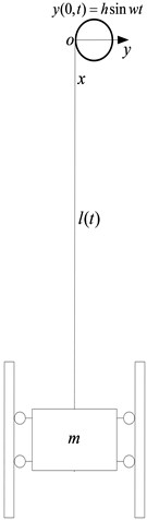
The vertical length of wire rope of the hoisting system changes as following expressions:
The speed of the wire rope changes as is shown in Fig. 2.
Fig. 2Speed curve of wire rope of hoisting system
Then setting the parameters of hoisting system as Table 1.
Table 1Parameters of hoisting system
Variable | Value |
Initial length of wire rope | 20 m |
Unit length mass of steel wire rope | 0.4 kg |
Elastic modulus of wire rope | 1e11 Pa |
Section bending resistance coefficient of steel wire rope | 4.9e-8 |
Time | 2 s |
Time | 8 s |
Time | 10 s |
Acceleration of hosting system | 0.1 m/s2 |
Amplitude of sine excitation | 0.002 m |
Frequency of sine excitation | 20 rad/s |
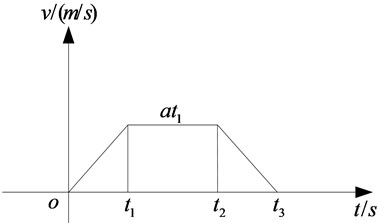
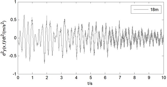
The transverse vibration displacement of wire rope in hoisting system can be obtained by solving the mechanical model established on computer simulation. Also, the transverse vibration displacement, velocity and acceleration of wire rope of the hoisting system at positions 18 m are analyzed, as are shown in the Fig. 3, Fig. 4 and Fig. 5.
From the observation of Fig. 3, Fig. 4 and Fig. 5, it can be found that when the excitation amplitude of the steel wire rope is 0.002 m and the excitation frequency is 20 Hz, the transverse vibration displacement of the steel wire rope at 18 m is between –0.005 m and 0.005 m, the transverse vibration displacement of the steel wire rope at 18 m is between –0.005 m and 0.005 m, the transverse vibration velocity is between –0.03 m/s and 0.03 m/s, and the transverse vibration acceleration is between –0.75 m/s2 and 0.75 m/s2. At the same time, the vibration frequency increases at the later operation process of the hoisting system, which is because of the reduction of the vertical length of the steel wire rope.
Fig. 3Transverse vibration displacement of wire rope at position 2 m
Fig. 4Transverse vibration velocity of wire rope at position 2 m
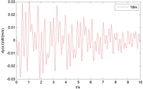
Fig. 5Transverse vibration acceleration of wire rope at position 2 m
5. Establishment of mechanical model
The transverse vibration analysis of steel wire rope in flexible hoisting system can be described not only by mathematical model, but also by mechanical model directly, and then the transverse vibration displacement can be analyzed. In the process of establishing the mechanical model of the transverse vibration of the steel wire rope of the flexible hoisting system, it is necessary to establish the mechanical model of the steel wire rope. As the steel wire rope is a continuous flexible elastic body, some methods should be adopted in the construction process. The common methods to build the mechanical model of steel wire rope are the beam model and the mass ball model. In the beam model, the two sections of the beam are coupled by bushing forces to form a continuous beam model, as is shown in Fig. 7. While in the mass ball model, the two mass balls are coupled by spring forces to form a discrete mass ball model. The mass ball model is shown in Fig. 6. The two methods can be used separately or in combination, depending on the system requiring being analyzed.
Fig. 6Mass sphere model
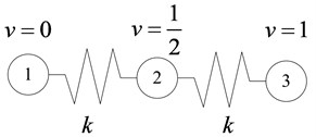
Fig. 7Beam model
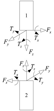
In order to ensure the reliability of the mechanical model of the steel wire rope and prevent the coupling failure of the beam model in the simulation process, a simplified method for building the steel wire rope model is adopted, that is, two sections of the cylinder are connected by hinges, and then the continuous beam is simulated. The simplified model is shown in Fig. 8.
Fig. 8Simplified model of wire rope

Table 2Parameters of flexible hoisting system
Variable | Value |
Length of wire rope | 20 m |
Radius of wire rope | 0.05 m |
Unit length mass of steel wire rope | 0.4 kg |
Radius of drum | 0.6 m |
Length of cylinder | 0.2 m |
Number of cylinder segments | 100 |
Mass of cylinder | 0.08 kg |
Weight of hoisting load | 100 kg |
Amplitude of sine excitation | 0.002 m |
Frequency of sine excitation | 20 rad/s |
In order to simulate the winding process of the steel wire rope on the drum, the steel wire rope should be divided into sections of cylinders so as to wind the drum smoothly. Therefore, in order to simulate the winding process and achieve efficient modeling at the same time, the length of the cylinder should be small. Here, the length of each steel cylinder is set as 0.2 m. At the same time, the total length of the simulated wire rope is 20 m to ensure the efficiency of modeling. Finally, in order to simulate the physical parameters of the actual steel wire rope as real as possible, the mass of the cylinder is consistent with the mass of the steel wire rope of actual length, which is 0.08 kg. And here, the mass of the steel wire rope of unit length is set to be 0.4 kg/m. The specific dynamic hoisting system parameters are shown in Table 2. In addition, the hoisting process of the drum adopts the four section curve motion diagram as shown in Fig. 2. The model of wire rope winding drum and the model of flexible hoisting system are shown in Fig. 10 and Fig. 9.
After the dynamic mechanical model of hoisting system is established, the transverse vibration displacement of wire rope can be analyzed.
Fig. 9Model of dynamic hoisting system

Fig. 10Model of wire rope winding drum

6. Analysis of mechanical model
In order to measure the transverse vibration displacement of the steel wire rope, 2 m away from the end of the steel wire rope is selected as the measuring point. The transverse vibration displacement and velocity of the steel wire rope at the position are measured to reflect the transverse vibration conditions of the steel wire rope with axial movement in the hoisting system.
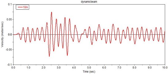
Then the dynamic analysis is carried out on the above flexible hoisting system model, and the transverse vibration displacement and velocity of the steel wire rope at positions 18m are obtained, as are shown in Fig. 11 and Fig. 12.
It can be found from Fig. 11 and Fig. 12, when the excitation amplitude is 0.002 m and the excitation frequency is 20 Hz, the transverse vibration displacement of the steel wire rope is between –0.0045 m and 0.003 m at 18 m, and the transverse vibration velocity is between –0.075 m/s and 0.075 m/s. This is because there is some error including modeling residual, elastic modulus residual and other residuals in simulating the vibration of the steel wire rope in the simulation software, so the amplitude of displacement and velocity have differences with the results of mathematical model.
Fig. 11Transverse vibration displacement of wire rope at position 18 m
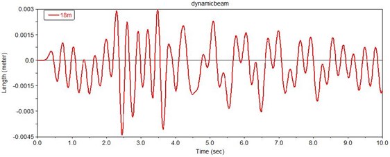
Fig. 12Transverse vibration velocity of wire rope at position 18 m
7. Comparison of results between the mathematical model and the mechanical model
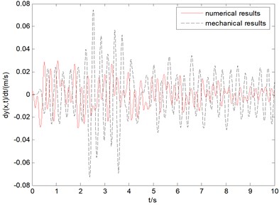
By comparing the transverse vibration displacement of the steel wire rope at 18m obtained from the mathematical analysis and the simulated analysis, it can be found that the mathematical analysis results are basically consistent with the simulated analysis results. Because there is a certain residual of modeling and elastic modulus in building the mechanical model of wire rope in the simulation environment, there is a small difference between the two results. However, this difference can be basically ignored to reflect the actual results. The results show that: under the excitation of amplitude of 0.002 m and frequency of 20 Hz at one end of the wire rope, the transverse vibration displacement at 18 m from one end of the wire rope is basically between –0.005 m and 0.005 m, and the transverse vibration velocity at 2 m from one end of the wire rope is basically between –0.04 m/s and 0.04 m/s. Finally, the transverse vibration frequency increases with the decrease of the length of the vertical part of the wire rope. The results are shown in Fig. 13 and Fig. 14.
Fig. 13Comparison of transverse vibration displacement
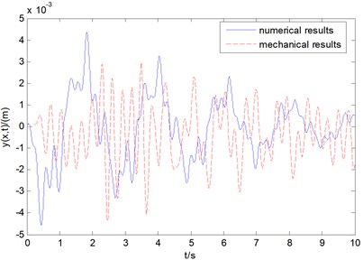
Fig. 14Comparison of transverse vibration velocity
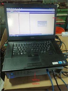
8. Experimental verification of a hoisting system
In order to further verify the validity of the mathematical model, the experiment is chosen to verify it. As a sine excitation is required, the head sheave is designed as an eccentric part with an eccentricity of 2 mm, as is shown in Fig. 15. The test bench is composed of programmable logic controller, motor, drum, head sheave, wire rope, guide and metal support, as is shown in Fig. 16. The test system consists of acceleration sensor, vibration test system, data processing software and PC, as shown in Fig. 17 and Fig. 18. The test bench parameters are shown in Table 3.
Table 3Parameters of flexible hoisting system of test bench
Variable | Value |
Length of wire rope | 1.8 m |
Radius of wire rope | 0.0015 m |
Radius of drum | 0.03 m |
Weight of hoisting load | 0.5 kg |
Amplitude of sine excitation | 0.002 m |
Fig. 15The eccentric head sheave realizing sine excitation
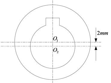
Fig. 16Test model of hoisting system
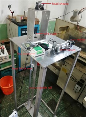
Fig. 17Acceleration sensor
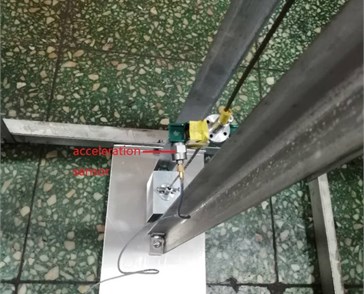
Fig. 18Testing system and software
By running the hoisting system, the transverse vibration acceleration at 0.2 m away from the end of the wire rope is obtained, as shown in Fig. 19. Acceleration can be found that the wire rope in the starting phase change is very small, this is because when the motor starts, there is a process to increase the torque of the motor, and during that time the wire rope does not move, so the horizontal vibration acceleration is very small. And it can be found that the transverse vibration acceleration of the wire rope is basically between –0.5 m/s2 and 0.5 m/s2.
Fig. 19Transverse vibration acceleration of wire rope at position 0.2 m
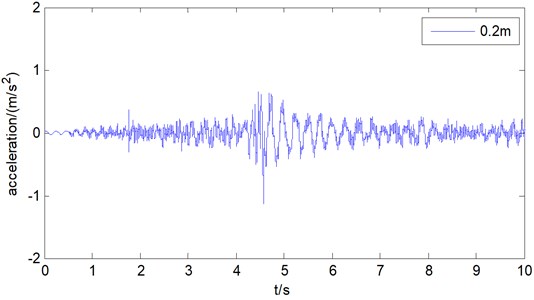
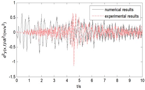
Fig. 20Comparison between results of numerical model and test bench
9. Comparison of results between the mathematical model and the experimental model
To compare the results of transverse vibration acceleration of the wire rope between numerical method and experimental method, as is shown in Fig. 20. It can be found that both results are basically between –0.5 m/s2 and 0.5 m/s2. So the validity of the mathematical model is verified.
10. Conclusions
This paper takes the flexible hoisting system as the research object, establishing the mathematical model and mechanical model of the transverse vibration of the steel wire rope of the flexible hoisting system, and analyzes the transverse vibration displacement, velocity and acceleration of the steel wire rope at 2 m away from one end of the rope when the other end of the steel wire rope is excited. Finally, the following four conclusions are drawn as below.
1) When the excitation amplitude at one end of the wire rope is 0.002 m and the excitation frequency is 20 Hz, the transverse vibration displacement at 2 m from one end of the wire rope with length of 20 m is basically between –0.005 m and 0.005 m, the transverse vibration velocity at 2 m from one end of the wire rope is basically between –0.04 m/s and 0.04 m/s, and the transverse vibration acceleration of the wire rope is basically between –0.5 m/s2 and 0.5 m/s2.
2) The transverse vibration frequency of the steel wire rope increases with the decrease of the length of the vertical rope.
3) The mathematical model and mechanical model of the flexible hoisting system were established, and through comparing the data, the numerical results and mechanical results are found basically consistent, indicating the validity of the established mathematical model and mechanical model.
4) The experiment of the flexible hoisting system were established, and through comparing the data, the numerical results and experimental results are found basically consistent, which indicate the validity of the established mathematical model and test bench.
The research and analysis results in this paper have certain reference significance and application value for the modeling, designing and analyzing of the flexible hoisting system.
References
-
Bao Ji Hu, Zhang Peng, Zhu Chang Ming Modeling and analysis of rope transverse vibration for flexible hoisting systems with time varying length. Journal of Shanghai Jiaotong University, Vol. 46, Issue 3, 2012, p. 341-345.
-
Kou Baofu, Liu Qiuzu, Liu Chunyang, et al. Characteristic research on the transverse vibrations of wire rope during the operation of mine flexible hoisting system. Journal of China Coal Society, Vol. 40, Issue 5, 2015, p. 1194-1198.
-
Wang Wen, Qian Jiang Finite difference method for simulating transverse forced-vibration of elevator suspended system. Journal of Vibration Engineering, Vol. 2, 2014, p. 26-31.
-
Mankowski A. Internal damping characteristics of a mine hoist cable undergoing non-planar transverse vibration. Journal of the South African Institute of Mining and Metallurgy, Vol. 88, Issue 12, 1988, p. 401-410.
-
Blodgett R. E., Majumdar A. K. An analysis of elevator rope vibration in tall buildings. Journal of Vibration Acoustics Stress and Reliability in Design, Vol. 105, Issue 1, 1983, p. 5-10.
-
Irvine H. M. Cable Structures. Massachusetts: the M.I.T. Press, Cambridge, 1981.
-
Tagata G. Harmonically forced, finite amplitude vibration of a string. Journal of Sound and Vibration, Vol. 51, Issue 4, 1977, p. 483-492.
-
Wickert J. A. Response and discretization methods for axially moving materials. Applied Mechanics Reviews, Vol. 44, Issue 11, 1991, p. 279.
-
Shabana A. A. Vibration of Discrete and Continuous Systems. Springer, 1997.
-
Bilbao S. Nonlinear transverse string vibration: model comparisons and numerical methods. The Journal of the Acoustical Society of America, Vol. 116, Issue 4, 2004, p. 2562.
-
Wang Dingxian, Yin Liang, Li Ying, et al. Modeling and dynamics simulation analysis for steel rope. Mining and Processing Equipment, Vol. 8, 2010, p. 20-23.
-
Zhang Chang You, Zhu Chang Ming, Fu Wu Jun Nonlinear lateral vibration of the hoist rope in vertical hoist system. Journal of Shanghai Jiaotong University, Vol. 38, Issue 2, 2004, p. 286-290.
-
Wang Zhi Gang, Sun Bing Nan Cable vibration for cable stayed bridge by parametric response. Engineering Mechanics, Vol. 1, 2001, p. 103-109.
-
Chen Shuisheng, Sun Bingnan, Hu Jun Analysis of stayed-cable vibration caused by axial excitation. Journal of Vibration Engineering, Vol. 2, 2002, p. 24-30.
-
Zhu W. D., Ni J. Energetics and stability of translating media with an arbitrarily varying length. Journal of Vibration and Acoustics, Vol. 122, Issue 7, 2000, p. 295-304.
-
Zhu W. D., Chen Y. Forced response of translating media with variable length and tension: application to high-speed elevators. Journal of Multibody Dynamics, Vol. 219, Issue 1, 2005, p. 35-53.
Cited by
About this article

