Abstract
Based on the theory of vehicle-bridge coupling vibration, the differential equation of vehicle-bridge coupling system is set up according to different conditions. The differential equation of the system is converted into matrix form using mode decomposition method and is solved using MATLAB. The system equation has a non-linear matrix term when the geometric nonlinearity of the bridge is considered. The influence of wheel acceleration on the dynamic response of the bridge is analyzed without simplification under four speeds. The results show that it is acceptable to neglect the influence of wheel acceleration at low speeds, but it has a significant influence which must be considered at high speeds.
Highlights
- The system equation has a non-linear matrix term when the geometric nonlinearity of the bridge is considered. The non-linear matrix is related only to the nature of the bridge structures.
- The system equation of vehicle-bridge coupling system without simplifying wheel acceleration is established.
- The influence of wheel acceleration on the bridge dynamic response is analyzed without simplification under four speeds.
1. Introduction
With the remarkable and increasing span and vehicle load of bridges, as well as the gradually decreasing mass and stiffness of bridge structures, much attention has been focused on the complexity and diversity of vehicle-bridge coupling vibration.
There are numerous methods of analyzing vehicle-bridge coupling vibration. Xia [1] presented a method of simplifying the bridge into a modal model to analyze the vehicle-bridge-pier system. Based on the finite element method, Chen [2] analyzed the resonance of a rigid-frame bridge under vehicle-bridge coupling vibration. Li [3] conducted in-depth analyses of the vehicle-bridge interaction under stochastic vibration. Shen [4] used an ODE function based on the Runge-Kutta method to compile a secondary development function which can solve the differential equation of the vehicle-bridge coupling system.
The influence of the geometric nonlinearity of the structures on the vehicle-bridge coupling vibration is important, especially for long-span and low-mass bridges. Considering the geometric nonlinearity of the bridge, it can be more realistic to analyze the dynamic response of the structure, which is of great theoretical and practical significance in the design and construction of the bridge structure.
2. Establishment of system equation considering the geometric nonlinearity of the bridge
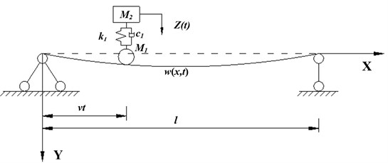
Fig. 1 shows the simply supported beam subjected to sprung mass, the vehicle system passes through the beam at a uniform speed , and denotes the dynamic deflection of the beam and the mass , respectively. Meanwhile, the displacement of the mass is consistent with the deflection of the beam at its position expressed as .
The main derivation process of the differential equation is as follows. First, the dynamic equilibrium equation of a simply-supported beam can be written as Eq. (1):
Fig. 1Simply supported beam subjected to sprung mass model
The dynamic equilibrium equation of can be written as:
The external load acting on the beam can be expressed as Eq. (3):
According to the mode decomposition method, the right end of Eq. (3) can be transformed into:
The left end of the Eq. (1) can be transformed into:
Therefore, Eq. (3) can be expressed as Eq. (6):
Similarly, using the mode decomposition method, the Eq. (2) can be written as:
By combining Eq. (6) and Eq. (7), the system dynamic equilibrium equations of the vehicle coupling with the simply-supported beam are obtained. The th order matrix expression of the system motion equation is:
where represents the generalized displacement vector, represents the generalized force vector, represents the generalized mass matrix, represents the generalized damping matrix and represents the generalized stiffness matrix, is used to describe the nonlinear matrix. This can be described by the following matrices:
where , , and .
It can be seen from the above derivations that in cases where the geometric nonlinearity of the bridge is taken into consideration, the system equation has a non-linear matrix term. It can be found that the non-linear matrix is related only to the nature of the bridge itself, and not to the parameters of the vehicle.
3. Establishment of system equation without simplifying wheel acceleration
The external load acting on the bridge is deduced by Eq. (6). In fact, the overall analysis of the vehicle shows that the external loads on the bridge can be expressed as Eq. (9):
where () represents the vertical acceleration of the vibration of the bridge at the position of the wheel, regardless of the change in the position of the load; () represents the vertical acceleration of the bridge caused by the movement of the load; () represents the vertical acceleration of the bridge caused by the curvature during structural vibration. The external loads on the bridge can be described by Eq. (11), which is calculated by substituting Eq. (10) into Eq. (9):
According to the mode decomposition method, the right end of Eq. (6) can be obtained and converted into the following equations:
The system dynamic equilibrium equations of a simply-supported beam, wheel and spring (damper) mass system can be obtained by combining Eq. (5), Eq. (13), Eq. (14) and Eq. (15).
The th-order matrix expression can be expressed as follows:
where:
4. Effect of velocity on dynamic response of bridge without simplifying wheel acceleration
For the dynamic response of the wheel mass coupled acceleration of a high-speed vehicle on the bridge, it is necessary to analyze the influence of the last two terms of Eq. (12) () and ) on the dynamic response of the vehicle-bridge coupling system [1, 5].
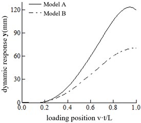
In this section, the influence of wheel acceleration on the bridge’s dynamic response is analyzed without simplification under four speeds: 20 m/s, 25 m/s, 30 m/s and 35 m/s. The calculating model of Eq. (12) is defined as Model A, and the model neglecting () and () is defined as Model B. Fig. 2 shows the vertical displacement response of the two models at different speeds. The maximum displacement of the structure and the maximum displacement ratio of the two models are shown in Table 1.
Table 1The dynamic responses of the bridge structure
velocity(m/s) | |||
20 | 79.1 | 74.2 | 1.0660 |
25 | 86.3 | 74.4 | 1.1599 |
30 | 99.1 | 73.1 | 1.3557 |
35 | 123.6 | 70.5 | 1.7532 |
andrepresent the maximum displacement in the span of Model A and Model B | |||
Fig. 2Comparisons of dynamic response of the mid-span at different speeds
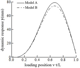
a)20 m/s
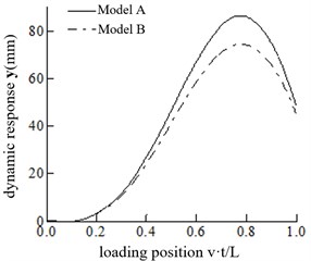
b)25 m/s
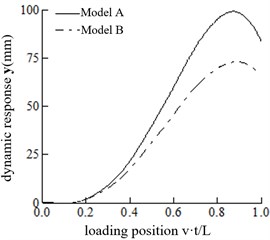
c) 30 m/s
d) 35 m/s
It can be observed that increases continuously with the increasing velocity. However, changes slightly with the increase in velocity, varying between 70 mm and 75 mm. With the increase in velocity, the position of the maximum mid-span displacement gradually recedes for both Model A and Model B. When the speed is 35 m/s, the maximum mid-span displacement of Model A and Model B occurs when the vehicle is about to leave the bridge.
When the speed is 20 m/s, Model A and Model B exhibit little difference in their mid-span displacement response. However, when the speed is 30 m/s, the ratio is 1.3557, and model A should be adopted. When the speed is 20 m/s 30 m/s, the appropriate model can be selected according to the calculation accuracy requirements.
5. Conclusions
In this paper, the effect of the geometric nonlinearity of bridges on the dynamic response of the vehicle-bridge coupling system is taken into account, and the following conclusions are obtained:
(1) The system equation has a non-linear matrix term when the geometric nonlinearity of the bridge is considered. The non-linear matrix is related only to the nature of the bridge structures, and the parameters of the vehicles have no influence on the matrix.
(2) The value of the non-linear matrix will increase as the inertia moment decreases when the other conditions remain unchanged.
(3) The influence of wheel acceleration on the bridge dynamic response is analyzed without simplification under four speeds. It is acceptable to neglect the influence of wheel acceleration at 20 m/s, while it is necessary to consider the significant influence of the wheel acceleration at 30 m/s.
References
-
Xia He, Chen Yingjun Dynamic interaction analysis of vehicle-beam-pier system. Journal of Civil Engineering, Vol. 2, 1992, p. 3-12.
-
Chen Shen, Tang Yi, Huang Wenji Visual study on vehicle vibration simulation of rigid frame arch bridge under multi vehicle load. Engineering Mechanics, Vol. 22, Issue 1, 2005, p. 218-222.
-
Li Xiaozhen, Cai Jing, Qiang Shizhong A comparative study on cable-girder anchorage structures of long-span steel box girder cable-stayed bridges. Engineering Mechanics, Vol. 21, Issue 6, 2004, p. 73-79.
-
Shen Huoming, Xiao Xinbiao A numerical method for solving the vibration problem of vehicle-bridge coupling. Journal of Southwest Jiaotong University, Vol. 38, Issue 6, 2003, p. 658-662.
-
Cao Xueqin Transverse Vibration of Steel Truss Bridge. China Railway Press, 1991.
About this article

This study was funded by the Natural Science Foundation of Chongqing under grant number cstc2018jscx-msyb1299, the Science and Technology Research Program of Chongqing Municipal Education Commission under the grant number KJZD-K201802501, the China Academy of Building Research under the grant number 20190112470730020.
