Abstract
The design of a new diverting roller table is presented, containing continuous series of sections with diverting rollers. Using the program product of finite element analysis of Autodesk Inventor, the stress-strain state rollers of the new outrigger roller table is calculated. It is proved that the maximum concentrations of stresses and deformations are observed in barrels and necks of rollers a new outrigger roller table. At the same time, the value of these indices is much smaller in comparison with the values of stresses and deformations occurring in existing roller tables.
1. Introduction
Modern steel rolling production is a complex, busy technological process, each link of which puts forward its specific requirements for electromechanical equipment. At the same time, the promising direction of modernization rolling equipment is the achievement of high quality products and a reduction in energy costs [1]. One of the directions to improve the quality of sheet rolling products and reduce energy costs is the diverting withdrawing roller table is the equipment included in the complete installation of the rolling mill, it operates under rather difficult conditions [2]. It should be noted that the rollers of the roller conveyor, is one of the massive elements, is subject to heavy wear and frequent breakages, which leads to significant roller conveyor failures [3]. Only because of the deterioration of the barrels of rollers of the roller conveyor CBM-1700 JSC “Arcelor Mittal Temirtau” during the year, about 280-330 rollers are out of order, that for the CBM-1700 roller table is up to 80 % of the annual roller consumption. These days, diverting rollers with a cast-iron barrel are used on hot rolled roll CBH rollers [4]. In addition to these, solid rollers are used, with a supporting axle and an antifriction bandage, rollers with transporting disks. These rollers satisfactorily provide the quality requirements for the strip surface [5]. However, the overwhelming majority of them, in addition to relative advantages, have a significant disadvantage, such as: increased metal consumption, low wear resistance, the presence of a large number interfaced elements, the complexity of design schemes complicating the installation and dismantling work, short life [6]. These shortcomings in the conditions of metallurgical enterprises characterized, as a rule, by a mass or large-scale type of metal production, lead to significant downtime of equipment and roller tables, in particular. It is known that the quality of the sheet material is significantly influenced by the condition of the surfaces rollers of the diverting roller, their relief [7]. The damage to the lower surface of the hot-rolled strips is mainly due to friction rollers of the roller tables of the mill. At the same time, the likelihood of the formation of scouring of risks and other mechanical damages increases in cases of severe wear on the surface of the rollers, improper installation and jamming.
2. Materials and methods
Nowadays, CAD-systems of medium level (for example, SolidWorks or Autodesk Inventor) with an integrated CAE-module integrated into it, designed for solving complex problems of mechanics deformable solid by the finite element method. Generator cylindrical gearing enables you to:
• Designing and inserting wheels;
• Designing and inserting the connection of two wheels;
• Inserting wheels as components, elements or only for calculations;
• Designing of wheels on the basis various initial parameters, for example number of teeth or distance between axes;
• Calculation of gears based on various strength testing methods for example, according to ANSI or ISO standards; calculation of power, speed or torque;
• Selection materials of cylindrical gearing.
Advantages this approach to the design of the gear stands of the diverting roller table are:
• The ability to create solid models of cage details in a single integrated design and calculation environment and calculate the stress-strain state of these parts at each point of their volume;
• The ability to simulate the assembly of individual assemblies and the entire stand as a whole;
• The possibility of automatic models to receive working drawings in compliance with the rules ESKD;
• Availability of libraries of standard products, materials and textures that relieve the user from the need to search in the reference literature and input data such as Poisson's ratio, modulus of elasticity, ultimate strength of materials, etc.
The calculation of the gears of the gear stand is made in the application “Generator of the components of the cylindrical gearing”, where geometric calculations are performed to select various distribution adjustments, including correction with slip compensation [1]. The generator calculates the geometric parameters of the gears, checks the dimensions and forces of the load, and also performs the strength test in accordance with the Bach, Merrit, CSN 01 4686, ISO 6336, DIN 3990, ANSI / AGMA 2001-D04: 2005 or ANSI standards.
Fig. 13D gear-stand model
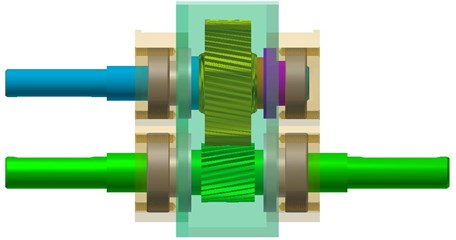
The calculation of the stressed-deformed state parts gear stand of the new outfitting diverting roller table is realized using the program of finite element analysis of Autodesk Inventor. The system of computer modeling Autodesk Inventor allows you to explore the kinematics, the dynamics of mechanisms with the ability to calculate the stress-strain, both individual elements and the design as a whole [2]. Using the standard program, Autodesk Inventor created a 3D model of a cylindrical gear stand for a new outrigger diverting roller table (see Fig. 1) and calculated stress distribution, contact pressure, displacement, safety factor, , and shifts, equivalent deformation in a gear stand. The assembly three-dimensional geometric model of the gear stand was built in the CAD program of Autodesk Inventor. For the possibility of automatic correction of the geometry tool model, the method of parametrization of the geometric dimensions construction was used. This method allows, based on the results of calculation for strength, to make appropriate changes in the design of the cogged stand [3]. As material for the gear stand, Autodesk Inventor was selected from a material database of 40XN grade with mechanical properties: a modulus of elasticity 206,000 MPa, a tensile strength 640 MPa, a yield stress 390 MPa and a Poison coefficient 0.3. Figs. 2-7 presents the results of a calculation in the form a pattern of the distribution equivalent stresses and deformations, displacements, contact pressure, and strength reserves of the power elements of the gear cage design [4].
3. Results and discussion
Carried on the finite element model calculations showed that:
• The maximum values of the equivalent stresses 31.3 MPa, (see Fig. 2(a)) and the deformation 0.00137, (see Fig. 2(b)) do not exceed the maximum permissible value for the given material’s strength 640 MPa. In this case, the maximum values of stresses and deformations are observed in the teeth and necks of the gear wheels [5, 6]:
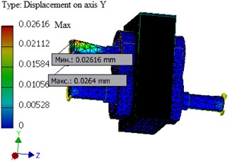
• The pattern of displacement distribution is consistent with the deformed shape of the structure shown in Fig. 3 and Fig. 4. The maximum displacement value is 0.0275 mm (along the axis), 0.0264 mm (along the axis) and 0.0012 mm, (along the axis) is observed in the teeth of the gears;
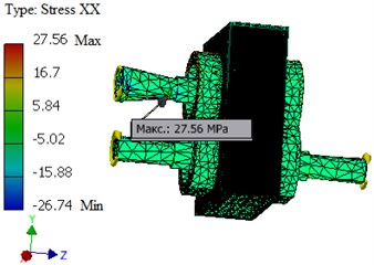
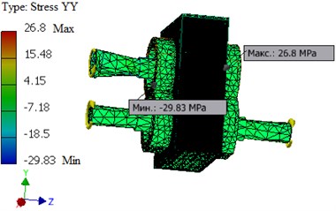
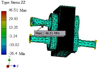
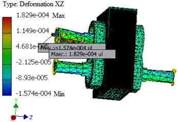
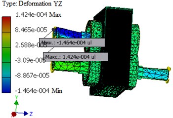
• The maximum values obtained for the components of the stress tensor = 27,5651 MPa, 29,8351 MPa, 46,51 MPa, 21,22 MPa, 28,25 MPa, 22,46 MPa (see Fig. 5), deformations 0.000122, 0.000139, 0.000192, 0.000123, 0.000183, 0.000143 (see Fig. 6) and contact pressures (see Fig. 7) do not exceed the maximum allowable strength 640 MPa for this material. In this case, the maximum values of stresses and deformations are observed in the teeth and necks of the gear wheels [7].
Fig. 2The pattern of equivalent stress distribution: a) and deformation, b) over the cross-section of the cogged stand
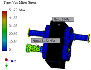
a)
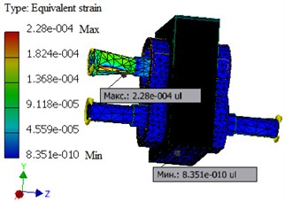
b)
Fig. 3The pattern of the distribution of the total displacement: a) and the displacement along the X, b) axis of the cogged stand
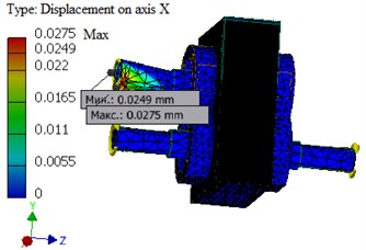
a)
b)
Fig. 4The pattern of distribution of stress tensor components: a) σxx, b) σyy, c) σzz in a cogged stand
a)
b)
c)
Fig. 5The pattern of distribution of stress tensor components: a) σxy, b) σxz, c) σyz in a cogged stand
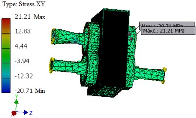
a)
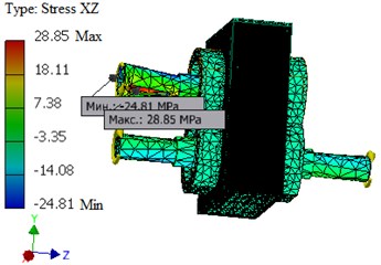
b)
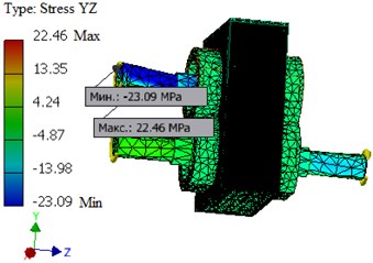
c)
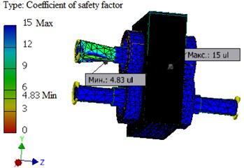
Distribution of safety factor by Fig. 7 as a whole satisfies the condition of strength, with the assumed safety factor of 5.
Fig. 6The distribution pattern of the components of the strain tensor: a) εxy, b) εxz, c) εyz in a cogged stand
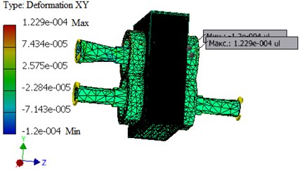
a)
b)
c)
Fig. 7The pattern of the distribution of the safety factor along the cross-section of the gear stand
4. Conclusions
To conclude, all the geometric dimensions of the parts included in the gear stand are determined. Strength calculations of gears have been carried out. It is established that the cogwheels with the calculated sizes will be operated without breakage. The results of the calculation obtained by the analytical method and using the Autodesk Inventor program are sufficiently consistent. The discrepancy value does not exceed 7-10 %.
References
-
Randak А. New solutions for steel and rolled iron manufacture. Ferrous Metals, Vol. 12, 1985, p. 8-14.
-
Guo Zhong-fenga, Sun Xue-yana, Wang Qia, Zhang Yib, Guo Huia. Simulation of shape control for CVC hot strip rolling. Procedia Engineering, Vol. 15, 2011, p. 1166-1170.
-
Deshpande A. S., Murthy K. S. Computer analysis for the prediction of a strip profile in cold rolling. Journal of Materials Processing Technology, Vol. 63, 1997, p. 712-717.
-
Waghulade Dipali G., Kolhe S. I. Optimization of work roll chock and backup roll chock in cold rolling mill. International Journal of Advanced Technology in Engineering Science, Vol. 4, Issue 7, 2016, p. 40-49.
-
Portman N. Application of neural networks in rolling mill automation. Iron and Steel Engineer, Vol. 72, Issue 2, 1995, p. 33-36.
-
Asch A., Hohn W. Monitoring system for roll stand drives using strain gage technology. Automation in Mining Mineral and Metal Processing, 1999, p. 159-164.
-
Dragomir S. Monitoring of iron sheet deformation in the rolling mill process by using CVC system. Proceedings of 12nd International Metallurgy Materials Congress, Istanbul, Turkey, 2005, p. 843-847.
About this article

