Abstract
During the past two decades, countless and valuable studies have been conducted on passive seismic control of structures on two-dimensional shear frame model and a few on three-dimensional shear frames. To simulate the actual behavior of buildings with higher accuracy, it is necessary to use more realistic and more complex models in evaluating the seismic performance and controller design. In this study, two indicators related to the structural damage and efficiency control have been used for the seismic control of the structure considering the soil-structure interaction (SSI) effect. with a detailed and complex three-dimensional finite element model in the OpenSees software, a twenty-story concrete structure is designed by the performance based plastic design (PBPD) method; the optimization process of control system and structure performance under the circumstances taken into account at the design stage have been studied. Seismic performance subjected to three acceleration records of far-field earthquake has been investigated and to consider the effects of SSI, the simplified cone physical model has been used. Results indicate that according to the type of soil for which the structure is designed, Tuned Mass Damper (TMD) cannot be reliably used to reduce lateral displacement of the structure, but TMD shows a proper performance in reducing inter-story drift
1. Introduction
With a preliminary research on passive seismic control systems and structures with obvious benefits, this type of systems mainly including the cost of all this equipment and easy manufacturing process; engineers began to make extensive use of them to reduce the structural loads due to wind and earthquake loads [1-4]. TMD is one of the simplest and most effective means of passive control with low maintenance costs increasing the structural performance in the face of environmental loads [5, 6]. This device includes a block weight added to the structure which is installed on the or like a pendulum is hanged from the ceiling. This weighted block is generally surrounded by several viscous springs and dampers to provide damping and stiffness. Public interest in the engineering community to these systems and especially TMD caused that, in order to make the vision of engineers real and to express the weaknesses and limitations along usage advantages of this type of systems, further studies to be conducted on the aspects of less.
In further complementary research carried out, regardless of the type of the structure (concrete or steel structure, linear or nonlinear materials [6-8]), the type of structural analysis, algorithms and different methods of optimization of TMD parameters [5, 9-11] and considering issues such as structural torsion [12-14], the topic that has not been considered is that the real structural response depends on the structure design philosophy and construction and unlike the gravity loading, seismic input energy is a function of the structure features and its design. For this reason, the nonlinear behavior of structures and phenomena such as pinching effect in the concrete structures should be considered from the beginning of design. In studies having been conducted so far, the structure with TMD has been designed linearly and its seismic performance has been evaluated and the linear and nonlinear analysis has been done for it. In this study, based on Performance-Based Plastic Design (PBPD), the structure nonlinear behavior has been considered from the beginning of the design process.
Another aspect that has been neglected in previous studies is the effect of soil in seismic behavior is the structure controlled by TMD. The past events indicate several severe damages occurred due to the neglect of the soil's effect during the earthquake [15, 16]. SSI effect importance has been identified through the research conducted during the past three decades on dynamic characteristics and seismic response of structures especially for heavy and stiff structures located on soft and relatively soft soil [15-18]. The results from the researches have clearly proven that conventional building codes cannot guarantee the safety of structures for buildings which are located on soft, fairly soft soils [15, 17, 18]. The effect of soil, referred in the science of seismic analysis of structures to soil-structure interaction effect, often leads to changes in the dynamic and vibrational characteristics of the structure. Of these characteristics are the increased period of vibration of the structure and the damping changes of the structure [15, 16]. These changes can easily detune TMD from the structure and result in the unpredictable behavior of TMD and in general, the goals and performance criteria of the structure that the designer has aimed by installing TMD in the structure have been distorted [19, 20]. Studies which investigate the effect of soil in the area of structures equipped with TMD are very limited and small and those few studies can be classified into two categories. In the first category, there are studies conducted on the optimization of TMD parameters [19, 21] and in the second category there are studies investigating SSI effect under wind load [4, 22] and earthquake load on single-story [23, 24] and multi-story structures [25, 26]. In 2016, Khoshnoudian et al [20] investigated SSI effects by studying three steel structures with linear behavior and TMD, under the excitation of near-field earthquake. The results showed that soil failure decreases TMD efficiency. It is worth noting that all studies have been conducted on the two-dimensional shear frames and assuming linear behavior of materials. In this study, it has been tried to obtain TMD optimum parameters by considering less attended aspects that have been already expressed from high rise concrete structure designed by PBPD and equipped with TMD through providing an accurate three-dimensional finite element model. For this purpose, time history analysis has been conducted on the twenty-story concrete structure model, under three far-field earthquake records. The advanced model Ibara [27] has been used for modeling concrete hysteresis behavior. To optimize TMD parameters, Tuned Mass Spectra [6] has been used, and the maximum lateral displacement of the structure and the maximum inter-story drift have been evaluated. In this study, using criteria related to structural response and damage and structural damage, it has been tried to realistically evaluate the performance of TMD in concrete structures.
2. Performance based plastic design method
In the current conventional methods, structures under seismic loads have been designed in elastic mode and the effects of nonlinear behavior of structures under severe earthquakes (decreased forces and increased displacements resulting from the elastic analysis respectively with coefficients such as behavior factor and displacement magnification ratio) are indirectly considered in the design process [28-30]. In 2008 PBPD design method was introduced by Goel and Chao for steel structures and then in 2010, this method was developed for concrete structures of special moment frame [31, 32]. The nonlinear behavior of structure is directly considered in this method and practically the necessity of assessment and repetition is eliminated by nonlinear static analysis or time history analysis after the initial design [32, 33]. For this reason, to simulate the actual behavior of buildings with greater precision, more realistic and complex models are used in the evaluation of performance and design and seismic control devices [28, 34, 35]. The basis of PBPD method theory is expressed using the concept of modal equivalent vibration of single degree of freedom (SDOF) systems with a multi-degree of freedom (MDOF) structure. In PBPD method, the relationship between the amount of energy needed to reach the structure to design target drift limit and input elastic energy will be obtained by using the inelastic response spectra for elastoplastic SDOF systems. This method is extended to multi-story structures by modal equivalent SDOF oscillators.
2.1. Summary of PBPD method steps
The steps of this design process can be summarized in five steps.
• The first step: Considering an appropriate yielding mechanism and target drift ratio, it is selected proportional to the performance objectives of design earthquake hazard. (At this step elastoplastic behavior is assumed for structure).
• Second step: Structural vibration period is estimated and an appropriate distribution relationship of the earthquake load in the height of the structure is selected.
• Third Step: Design -based shear force is obtained for a hazard level selected, considering the work required to bring the structure to the target drift ratio uniformly equal to the energy required for an elastoplastic SDOF structure.
• Step Four: If material behavior does not follow elastoplastic behavior, design- based shear force should be modified.
• Step Five: Members entered the area of nonlinear behavior (such as beams in reinforced concrete moment frame) designed using plastic method based on the amount of imported energy and elastic members (Non-Designated Yielding Members) such as columns will be designed using a capacity based method.
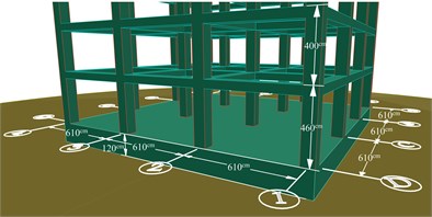
Fig. 1Three-dimensional plan of concrete twenty-story structure
2.2. Design of twenty-story concrete structure using PBPD method
Three-dimensional plan intended for the structure has been shown in Fig. 1. The location of the structure site, Los Angeles, California with high seismic risk in accordance with the regulations ASCE7-10 [29] with soil type Category D has been assumed with specifications outlined in the regulations. The opening of the frames forming the structure has the length of 610 cm and the height of structure on the first floor and other floors were equal to 460 cm and 400 cm, respectively. Concrete compressive strength for columns and foundation of the structure has been considered 42 MPa and for beams it has been considered equal to 35 MPa. Target drift ratio of 2 % and yield drift ratio equal to 0.5 % have been assumed. Floors dead load and live load were respectively considered equal to 850 and 240 kilograms per square meter. According to the hypothesis, which included specifications for design and design process described in the previous section, a twenty-story concrete structure of special moment frame has been designed based on PBPD method. Frame view has been shown in Fig. 2 with full profile.
3. Structural modeling
3.1. Cone model characteristics of soil
To consider the effect of SSI, the Physical Cone model has been used (Fig. 3). This model has consisted of a set of springs, dampers and masses concentrated below the foundation. In this model, it is assumed that different degrees of freedom do not interfere with each other. This model has good accuracy in the range of engineering errors. The modeling and especially analysis time is significantly reduced compared to models based on finite element [16]. According to soil level considered at the design stage, shear wave velocity of the soil of 300 meters per second and Poisson’s ratio of 0.3 are considered. With respect to the relationship proposed by Zhang and Wolf [16], the numerical values of the cone model are obtained equal to those provided in Table 1.
Fig. 2View of twenty-story frame designed by PBPD
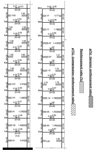
Table 1Key parameters for three-dimensional modeling of soil-foundation-structure system on semi-infinite substrate of soil [16]
Motion | |||
Horizontal | Rocking | Torsional | |
Equivalent radius (m) | 10.31 | 10.43 | 8.77 |
(m) | 0.66 | 1.08 | 0.88 |
Aspect ratio | 6.80 | 11.26 | 7.71 |
Wave velocity C | 300 m/s | 396.86 m/s | 300 m/s |
Trapped mass | 0 | 0 | 0 |
Lumped-parameter model | 8.12×10⁸ kgf/m 1.84×10⁷ kgf/m | 7.17×10¹⁰ kgf/m 6.79×10⁸ kgf/m | 5.98×10¹⁰ kgf/m 5.13×10⁸ kgf/m |
3.2. Features of the structural model
Nonlinear structure analysis and modeling based on false and unrealistic methods can lead to incorrect and unreasonable answers. There are many finite element models for concrete structures. However, most of them are not able to simulate the structural failure. In 2005, the hysteretic model was proposed for the behavior of reinforced concrete elements of beam and column named Ibara model, by Ibara et al. [27]. This model can consider the important modes of deterioration and decrease in resistance, which can cause the collapse of structural components. In this study, the hysteresis model has been used for modeling the nonlinear behavior of beam and column elements. To simulate the structural behavior of beams and columns, in the OpenSees finite element software, a beam-column element was used (Fig. 4) consisting an elastic element and two moment plastic joints focused at both ends and with a length of zero. As to define the structural nodes, in addition to the main structural nodes, at the site of each plastic hinges, two nodes with the same coordinates have been defined so that, for a detailed definition of plastic hinge, a zero-length element has been defined between these two nodes. In addition to the nodes mentioned above, an additional node in each floor has been placed in the center of the floor area, which is on the center of mass of each floor and it has been used to create rigid diaphragms in each floor. To consider the SSI effect, a node at the bottom of the structure is first defined at the center of its area, and the degree of freedom has been assumed to be restrained in the vertical direction. In the second stage, another node has been defined at the same coordinates and all its degrees of freedom are restrained. In the third step, a zero-dimensional element has been defined between these two nodes and the springs and dampers of the soil model with the characteristics obtained in each of the longitudinal and rotational directions have been used. In the fourth stage, the nodes of the bottom of the floor of the structure are connected by a rigid element to the first stage node.
Fig. 3a) a general view of the structure with a cone model and TMD, b) details of the cone model of soil, c) details of the upper floors of structure
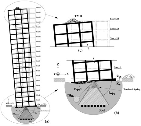
Fig. 4Model of reinforced concrete beam and column element [32]
![Model of reinforced concrete beam and column element [32]](https://static-01.extrica.com/articles/18628/18628-img4.jpg)
3.3. Applied base excitations
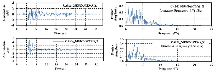
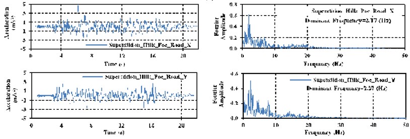
Time history analysis on the presented structural model has been done by three acceleration far-field earthquake records, for TMD parameters optimization. These earthquakes are each formed of two acceleration records in two directions perpendicular to each other (along the and ). The graph of applied acceleration record and Fast Fourier Transform Graph (FFT Graph) to determine the dominant frequency have been depicted in Fig. 5.
Fig. 5Acceleration record of earthquakes applied to structure, along with their corresponding Fast Fourier transform graphs: a) the Cape-Mendocino, b) superstition-hills, c) Manjil-Abbar earthquakes
a)
b)
c)
4. Survey of the results of analysis and optimization parameters of TMD
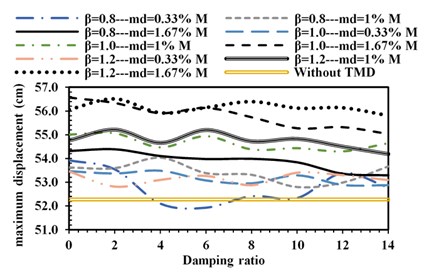
Tuned Mass Spectra is a powerful method to study the effects of TMD, under a special earthquake [6]. so that, in this study using this method and time history analysis on three-dimensional model of twenty-story concrete structure under selected earthquakes, the graph of changes in objective functions has been obtained. The objective functions in optimizing the TMD parameters are the maximum lateral displacement and the maximum inter-story drift of the structure. The optimization process is based on a numerical approaches recently used by Shooshtari and Mortezaie [6]. In this method, by considering a series of variation intervals for the three main TMD parameters, which include mass ratio, tuning ratio and TMD damping ratio, the optimization process has been conducted with structural analysis under each of these states and obtaining maximum lateral displacement and inter-story drift values of the structure. Parameters of TMD, for which the best performance of TMD is observed, are discussed below.
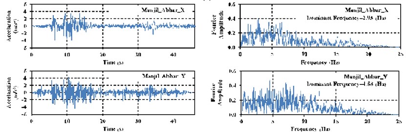
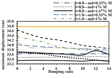
Fig. 6Maximum lateral displacement under: a) Cape-Mendocino, b) superstition-hills, c) Manjil-Abbar earthquakes
a)
b)
c)
Damping, mass ratio and tuning ratio of TMD are three main parameters in the design of this passive control device. The mass ratio is obtained by dividing the mass of damper () by the total mass of the structure (). The tuning ratio () (or the tuned frequency ratio) is obtained from the following expression:
where, is the main oscillation frequency of the structure.
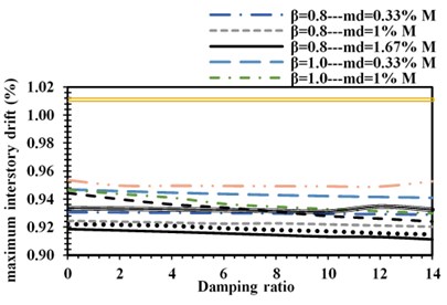
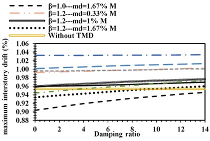
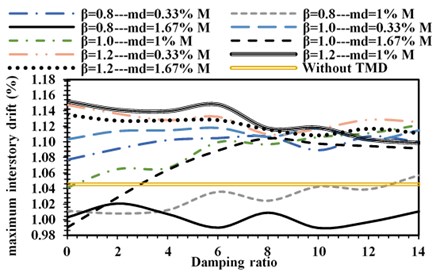
The range intended to optimize the TMD parameters for mass ratio, tuning ratio and TMD damping ratio is [033 %-1.00 %-1.67 %], [0.8-1.0-1.2], and [0-2-4-6-8-10-12-14]. Fig. 6 and Fig. 7 indicate the variation spectrum of two objective functions under three earthquakes, obtained by 216 times of history analysis in different proportions of the values of the TMD parameters. As is clear from the survey of the results of Fig. 6, TMD in the lateral displacement control is sensitive to the earthquake, so that in the earthquakes Cape-Mendocino and Superstition-hills the TMD can be set to improve the performance of the structure. But given the uncertainty in determining the amount of load and evaluating the graph of displacement changes caused by Manjil-abbar earthquake, optimal parameters cannot certainly be recommended, although at the mass ratio of 0.33, and the tuning ratio of 0.8 and damping of 6 %, TMD under Manjil-abbar earthquake has led to improve structural performance.
But as a general rule it can be said that by increasing the mass ratio of the TMD under a particular earthquake, a better performance of TMD will be observed. By analyzing the results, it seems that with the nonlinear seismic behavior of structure, damping of TMD is less effective than the other two other parameters. Therefore, to control the structural displacement, the optimal TMD parameters are considered in way that under the earthquakes of Cape-mendocino and Superstition-hills with a mass ratio of 1.67 %, tuning ratios of 0.8 and 1.0 and damping of 14 % and zero, the best performance of the structure will be observed. These values under Manjil-abbar earthquake change to mass ratio of 0.33 %, tuning ratio of 0.8 and damping ratio of 6 %. Accordingly, by tuning the TMD with ratios given under earthquake Cape-mendocino, a reduction of 4.2 % and under Superstition-hills the reduction of 5.6 % under Manjil-abbar earthquake the reduction of 0.7 % in lateral structural displacement will be observed. Unlike the not-so-good performance of TMD in structural displacement control, as is clear from Fig. 7 in inter-story drift control it shows better performance. As by tuning TMD with the mass ratio of 1.67 % and tuning ratios of 0.8 and 1.0 and damping of 14 %, zero and 10 % respectively for the earthquakes Cape-mendocino and Superstition-hills and Manjil-abbar will decrease by 9.9 %, 5.3 % and 5.4 %.
Fig. 7Maximum Inter-story drift of structure under: a) Cape-Mendocino, b) superstition-hills, c) Manjil-Abbar earthquakes
a)
b)
c)
According to the dominant frequency of earthquakes studied (Fig. 5) and the first and second oscillation frequency of the structure of 3.24 Hz and 8.77 Hz, respectively, it seems that in tuning TMD, in addition to the oscillation frequency, the earthquake dominant frequency should also be considered because it was found that the optimum tuning frequency of TMD, in most cases, is less than main oscillation frequency of the structure while in a number of previous studies, the natural frequency of the damper is set at a specific frequency, which is generally close to the fundamental oscillation frequency of the structure [36, 37]. As, the search for the maximum value of parameters alone cannot find a clear view of the performance of TMD, in Figs. 8-9 the structural displacement and inter-story drift in three modes have been investigated under each earthquake separately.
• Structure with optimized TMD & SSI.
• Structure without TMD & with SSI.
• Structure without TMD & SSI.
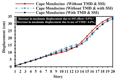
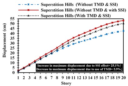
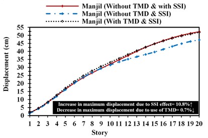
Fig. 8Lateral structural displacement changes in the various stories of structure: a) Cape-Mendocino, b) superstition-hills, c) Manjil-Abbar earthquakes
a)
b)
c)
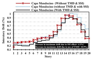
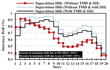
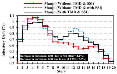
In Fig. 9, the inter-story drift changes have been investigated by all three far-field earthquakes. As it is known, with considering the SSI effect, the drift of the structure in the upper floors of the structure under the two Manjil-Abbar and Superstition-hills earthquakes has increased significantly. The same increase occurred under the earthquake of Cape-Mendocino with lower intensity. The reduction percent in the maximum inter-story drift of the entire structure due to the use of TMD and its increase due to the effect of soil-structure interaction under each earthquake has also been shown in Fig. 9. Although under the Manjil-Abbar earthquake, a decrease in the maximum inter-story drift, due to the SSI effect is observed, however, as shown in Fig. 9, in other stories, the SSI effect has increased the inter-story drift value. By equipping the structure with TMD reducing the amount of inter-story drift can be observed in all the floors. However, the SSI effect causes an increase in the inter-story drift and TMD reduces this increase. This could show that although the TMD considering SSI effect is not very successful in structural displacement control. Along with the inter-story drift which is associated with damage to structure, it can be concluded that TMD effectively reduces the structural damage.
Fig. 9Maximum inter-story drift in different structural stories: a) Cape-Mendocino, b) superstition-hills, c) Manjil-Abbar earthquakes
a)
b)
c)
5. Conclusions
In this study, constructing a three-dimensional finite element model of a high-rise with a concrete structure designed by PBPD, the effects of SSI under far-field earthquake and nonlinear behavior of structure have been studied. Results indicate that in lateral structural displacement control, TMD is very sensitive to the type of earthquake and does not show the reliable and desirable performance to control the displacement of the structure. But in inter-story drift control associated with structural damage it acts more effectively. The effect of SSI increases the displacement and inter-story drift relatively. Neglecting the effect of SSI, in adjusting and optimizing the TMD parameters, causes the detuning TMD from the structure and this can easily undermine the goals and performance criteria of the structure, which has been attempted by the installation of TMD in the structure. For this reason, considering the SSI effect and using three-dimensional structural analysis is recommended to engineers in the structural seismic control in order to consider the effects such as torsion in executive projects. Considering the considerable number of different earthquakes to ensure the performance of TMD and the optimum parameters considered seems necessary. The use of TMD with a variable stiffness can also improve the seismic performance of structures in the lateral structural displacement control.
References
-
Housner G. W., Bergman L. A., Caughey T., Chassiakos A., Claus R., Masri S., et al. Structural control: past, present, and future. Journal of Engineering Mechanics, Vol. 123, 1997, p. 897-971.
-
Sadek F., Mohraz B., Taylor A. W., Chung R. M. A method of estimating the parameters of Tuned Mass Dampers for seismic applications. Earthquake Engineering and Structural Dynamics, Vol. 26, 1997, p. 617-635.
-
Soong T. T., Dargush G. F. Passive Energy Dissipation Systems in Structural Engineering. John Wiley and Sons, Chichester, 1997.
-
Liu M.-Y., Chiang W.-L., Hwang J.-H., Chu C.-R. Wind-induced vibration of high-rise building with tuned mass damper including soil-structure interaction. Journal of Wind Engineering and Industrial Aerodynamics, Vol. 96, 2008, p. 1092-1102.
-
Gerges R. R., Vickery B. J. Optimum design of pendulum‐type tuned mass dampers. The Structural Design of Tall and Special Buildings, Vol. 14, 2005, p. 353-368.
-
Shooshtari M., Mortezaie H. Effect of using linear multiple tuned mass dampers on concrete structures with hysteresis behavior. Journal of Vibroengineering, Vol. 19, Issue 2, 2017, p. 1158‑1172.
-
Sgobba S., Marano G. C. Optimum design of linear tuned mass dampers for structures with nonlinear behaviour. Mechanical Systems and Signal Processing, Vol. 24, 2010, p. 1739-1155.
-
Aguirre J. J., Almazán J. L. Damage potential reduction of optimally passive-controlled nonlinear structures. Engineering Structures, Vol. 89, 2015, p. 130-146.
-
Bakre S. V., Jangid R. S. Optimum parameters of tuned mass damper for damped main system. Structural Control and Health Monitoring, Vol. 14, 2007, p. 448-470.
-
Greco R., Marano G. C. Optimum design of tuned mass dampers by displacement and energy perspectives. Soil Dynamics and Earthquake Engineering, Vol. 49, 2013, p. 243-253.
-
Aguirre J., Almzán J. Optimum seismic design of nonlinear asymmetric structures controlled by large tuned mass dampers. 10th U.S. National Conference on Earthquake Engineering Frontiers of Earthquake Engineering, 2014.
-
Singh M. P., Singh S., Moreschi L. M. Tuned mass dampers for response control of torsional buildings. Earthquake Engineering and Structural Dynamics, Vol. 31, 2002, p. 749-69.
-
Li C., Qu W. Optimum properties of multiple tuned mass dampers for reduction of translational and torsional response of structures subject to ground acceleration. Engineering Structures, Vol. 28, 2006, p. 472-94.
-
Tse K., Kwok K., Tamura Y. Performance and cost evaluation of a smart tuned mass damper for suppressing wind-induced lateral-torsional motion of tall structures. Journal of Structural Engineering, Vol. 138, 2012, p. 514-25.
-
Mylonakis G., Gazetas G. Seismic soil-structure interaction: beneficial or detrimental? Journal of Earthquake Engineering, Vol. 4, 2000, p. 277-301.
-
Zhang C., Wolf J. P. Dynamic Soil-Structure Interaction: Current Research in China and Switzerland. Elsevier, 1998.
-
De La Colina J., Valdés González J., González Pérez C.-A. Experiments to study the effect of foundation rotation on the seismic building torsional, response of a reinforced concrete space frame. Engineering Structures, Vol. 56, 2013, p. 1154-1163.
-
Tahghighi H., Rabiee M. Nonlinear soil-structure interaction effects on building frames: a discussion on the seismic codes. Journal of Seismology and Earthquake Engineering, Vol. 17, Issue 2, 2015, p. 141-151.
-
Khatibinia M., Gholami H., Labbafi S. Multi-objective optimization of tuned mass dampers considering soil-structure interaction. International Journal of Civil Engineering, Vol. 6, 2016, p. 595-610.
-
Khoshnoudian F., Ziaei R., Ayyobi P. Effects of nonlinear soil–structure interaction on the seismic response of structure-TMD systems subjected to near-field earthquakes. Bulletin of Earthquake Engineering, 2016, p. 1-28.
-
Bekdaş G., Nigdeli S. M. Metaheuristic based optimization of tuned mass dampers under earthquake excitation by considering soil-structure interaction. Soil Dynamics and Earthquake Engineering, Vol. 92, 2017, p. 443-461.
-
Xu Y., Kwok K. Wind-induced response of soil-structure-damper systems. Journal of Wind Engineering and Industrial Aerodynamics, Vol. 43, 1992, p. 2057-2068.
-
Ghosh A., Basu B. Effect of soil interaction on the performance of tuned mass dampers for seismic applications. Journal of Sound and Vibration, Vol. 274, 2004, p. 1079-1090.
-
Wang J.-F., Lin C.-C. Seismic performance of multiple tuned mass dampers for soil-irregular building interaction systems. International Journal of Solids and Structures, Vol. 42, 2005, p. 5536-5554.
-
Wu J., Chen G., Lou M. Seismic effectiveness of tuned mass dampers considering soil-structure interaction. Earthquake Engineering and Structural Dynamics, Vol. 28, 1999, p. 121912-33.
-
Takewaki I. Soil-structure random response reduction via TMD-VD simultaneous use. Computer Methods in Applied Mechanics and Engineering, Vol. 190, 2000, p. 677-690.
-
Haselton C. B. Assessing Seismic Collapse Safety of Modern Reinforced Concrete Moment Frame Buildings. Stanford University, 2006.
-
Moehle J. P., Hooper J. D., Lubke C. D. Seismic design of reinforced concrete special moment frames: a guide for practicing engineers. NEHRP Seismic Design Technical Brief, 2008.
-
Minimum Design Loads for Buildings and Other Structures: ASCE Standard 7-10: American Society of Civil Engineers, 2010.
-
ACI 318-14 Building Code Requirements for Structural Concrete and Commentary American Concrete Institute, 2014.
-
Goel S. C., Liao W. C., Reza Bayat M., Chao S. H. Performance‐based plastic design (PBPD) method for earthquake‐resistant structures: an overview. The Structural Design of Tall and Special Buildings, Vol. 19, 2010, p. 115-137.
-
Liao W.-C. Performance-Based Plastic Design of Earthquake Resistant Reinforced Concrete Moment Frames: ProQuest. UMI Dissertations Publishing, 2010.
-
Grigorian M., Grigorian C. E. A new performance based design approach for moment resisting frames. Canadian Journal of Civil Engineering/Revue Canadienne de Genie Civil, Vol. 39, 2012, p. 473-483.
-
Moehle J. P., Mahin S. A. Observations on the behavior of reinforced concrete buildings during earthquakes. Special Publication, Vol. 127, 1991, p. 67-90.
-
Nigdeli S. M., Boduroğlu M. H. Active tendon control of torsionally irregular structures under near-fault ground motion excitation. Computer‐Aided Civil and Infrastructure Engineering, Vol. 28, 2013, p. 718-736.
-
Adam C., Furtmüller T. Seismic performance of tuned mass dampers. Mechanics and Model-Based Control of Smart Materials and Structures, 2010, p. 11-18.
-
Lee C.-L., Chen Y.-T., Chung L.-L., Wang Y.-P. Optimal design theories and applications of tuned mass dampers. Engineering Structures, Vol. 28, 2006, p. 43-53.
Cited by
About this article

