Abstract
In order to study the effects of the impeller outlet width on the flow noise of the centrifugal pump, a centrifugal pump is applied in the paper as the research object. Geometric parameters of the pump and impeller are constant, and BEM (Boundary Element Method) and experimental method are adopted to analyze noises when the impeller outlet width is 8 mm, 10 mm, 12 mm and 14 mm, respectively. Firstly, Large-eddy simulation method is applied to compute the transient flow field of the centrifugal pump. Larger pressures and flow velocity of the centrifugal pump mainly are at the edge of the impeller. When the fluid flows from the centrifugal pump, there are two obvious separation vortexes at the outlet of the centrifugal pump. The flow velocity distribution of the centrifugal pump in the horizontal plane is basically symmetric. Based on modal analysis and the transient flow field of the pump, BEM is adopted to compute the noise in the centrifugal pump caused by the unsteady flow, and experiments are also conducted for verification. Based on the above analysis, the noise in the interior and exterior field of the centrifugal pump is computed, and the effects of the impeller outlet width on the noise of the centrifugal pump are then studied. As shown from the result, the radiation sound power at the characteristic frequency increases with the increase of the impeller outlet width. With a reasonable range, the impeller outlet width makes the sound pressure level (SPL) in the interior and external field of various flow conditions be smaller. Considering the energy performance and flow field noises of the centrifugal pump, the pump has the optimal comprehensive performance at the impeller outlet width of 10 mm. The research results can be applied to provide a reference for the optimization design of the centrifugal pump with low vibration and noise.
1. Introduction
At present, the centrifugal pump has become a main technique for recycling liquid energy and is widely used in the important field including petroleum, chemical engineering and so on [1-4]. To improve the recovery rate of energy, the centrifugal pump is gradually developing towards the direction of large power. However, flow-induced noises are one of key problems affecting its operation.
The noise of the centrifugal pump includes mechanical vibration noises and flow-induced noises. Currently, the probability of mechanical failure is very low due to precise mechanical design and processing. Therefore, mechanical noises are relatively low. Flow-induced noises are more complex [5]. Chu [6, 7] pointed out that interactions between the blade and separation tongue as well as non-uniform flow of impeller outlet were main reasons of local pressure pulsation and far-field noises, and noise peaks appeared when the wake hit the separation tongue. Byskov [8] studied the vibration and noises of a multistage centrifugal pump, and it was shown that the computed result of pressure pulsation under the design point and off-design points was consistent with that of the experiment. Parrondo [9] used CFD and vibration noise simulation technology to conduct on related studies on the flow-induced noise of the centrifugal pump. Results showed that the unsteady flow of the impeller and static-dynamic coupling effect of separation tongue had a great influence on flow-induced noises. Langthjem [10] conducted on numerical computation for the flow and sound field of 2D centrifugal pump, and results showed that unsteady pressure on the surface of the blade was the main reason for the internal noise of the centrifugal pump. Kato [11] studied turbulence-induced noises of the multistage centrifugal pump based on large-eddy simulation, and found that interaction between dynamic and static blades was the main source of noises. Huang [12] adopted large-eddy simulation and FW-H acoustic model to study the influence of long-short blades on the noise radiation of the centrifugal pump. Results showed that long-short blades could change the distribution of noises in the frequency domain. Jiang [13] combined CFD with the vibro-acoustic coupling method to conduct on numerical simulation of the hydrodynamic noise of the centrifugal pump. Results showed that coupling must be considered when the noise of the centrifugal pump was computed. However, most of the above studies were conducted from the perspective of numerical simulation and lacked experimental verification. Additionally, numerical simulation adopted 2D model which could not accurately reflect the detailed characteristics of the centrifugal pump.
This paper firstly adopts large-eddy simulation to compute the flow field characteristics of the centrifugal pump under four flow conditions. Then, the flow field result of the centrifugal pump and the mesh model of BEM are imported into Virtual.Lab to conduct on coupling computation and obtain the internal and external sound field of the centrifugal pump. Finally, the computational result is compared with that of the experiment for verification.
2. Geometric model and mesh of the centrifugal pump
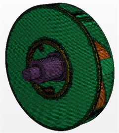
The computational model is a single-stage and single-suction centrifugal pump. As shown in Fig. 1, design parameters are as follows: flow 50 m3/h, pump head 34 m, rotating speed 2900 r/min, inlet diameter 75 mm, outlet diameter 174 mm, impeller outlet width 10 mm, number of blades 6, volute base diameter 184 mm, and volute base width 20 mm. When the numerical computation is conducted, the centrifugal pump should lengthen the outlet to ensure high computation accuracy. When the computational domain is divided into meshes, hexahedral meshes are adopted with considering the complex shape of the model. Meanwhile, boundary layer meshes [14] are adopted. The number of boundary layers is 5. Growth rate is 1.1. Total thickness is 0.0017 mm. Finally, the number of meshes is 1361334, meshes in inlet section are 115058, meshes in impellers are 582673 and meshes in outlet section are 135185. The mesh model of the computational domain and the impeller is shown in Fig. 2.
Fig. 1Geometric model of the centrifugal pump
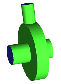
a) Primary structure
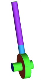
b) Computational domain
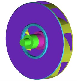
c) Impeller
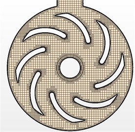
Fig. 2Mesh model of the centrifugal pump
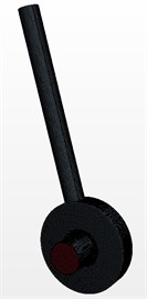
a) Computational domain
b) Impeller
c) Blade section
3. Computation of flow field
3.1. Control equation
3D flow field in the centrifugal pump is solved by CFD, and turbulent effect is simulated based on LES method. The filter function is adopted to filter N-S equation, thus obtaining LES control equation [15-17]. The incompressible continuity equation and N-S equation are as follows:
wherein, (1, 2, 3) represents the velocity component in parallel to the coordinate axis . is time. is the density. is the intensity of pressure. is the motion viscosity. is the sub-grid scale stress tensor. is the source term generated from Coriolis force.
Through the eddy viscosity , the relationship between the sub-grid scale stress tensor and large-scale strain rate tensor is established as follows:
In the study, the wall-adapting local eddy-viscosity (WALE) model is applied to solve the eddy viscosity. A dimensionless coefficient is contained in this model, which is defined as follows:
wherein, is the filter length, depending on the grid volume (), and model coefficient is chosen as 0.1.
3.2. Computational boundary conditions and results
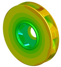
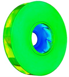
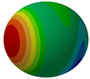
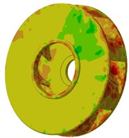
The inlet of the centrifugal pump is set as static pressure and outlet is set as mass. In the computational domain, all surfaces adopt the condition of no-slip wall and roughness is set according to the actual accuracy. Turbulence model adopts - model. The value of is about 1. Scalable wall function is selected. Computational accuracy is 0.00001. To clearly distinguish the unsteady information of the internal flow field, time step is set as 1.1×10⁻⁴ s. Namely, the impeller in every time step rotates about 1°. After the flow field presents a stable periodical change, the information of pressure pulsation of the impeller and shell surface starts to be exported. Finally, the pressure and velocity distribution of the centrifugal pump are shown in Fig. 3 and Fig. 4 respectively. As shown in Fig. 3, larger pressure of the centrifugal pump mainly appears at the edge position of the impeller. Larger flow velocity and impact force are produced when fluid flows into the centrifugal pump and bears the inertia effect of high-speed revolution of the centrifugal pump, which leads to larger pressure in volute of the centrifugal pump. Fig. 4 shows the distribution of flow velocity at the impeller of the centrifugal pump, from which it can be seen that flow velocity at the center of the impeller is relatively small and flow velocity at the edge of the impeller is relatively large.
Fig. 3Contour of pressure distribution of the centrifugal pump
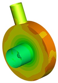
a) Centrifugal pump
b) Impeller

c) Blade
Fig. 4Contour of flow velocity distribution of the impeller
a) Impeller
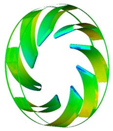
b) Blade
The flow velocity distribution of the centrifugal pump is extracted and shown in Fig. 5. As can be seen from the figure, fluid will be thrown away from the outlet under the action force of high-speed revolution of the centrifugal pump when fluid flows into the internal of the centrifugal pump from the inlet. In addition, there are two obvious separation vortexes in the outlet. The flow velocity distribution of the centrifugal pump in the horizontal plane is basically symmetric.
Fig. 5Flow velocity distribution of the centrifugal pump
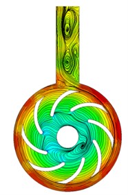
a) Vertical plane
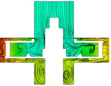
b) Horizontal plane
4. Computation and experimental verification of flow noises of the centrifugal pump
4.1. Numerical calculation model of flow noises of the centrifugal pump
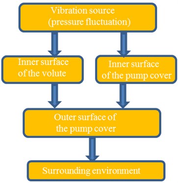
The noise of the centrifugal pump mainly contains mechanical vibration noises and flow-induced noises. Compared with flow noises, mechanical noises are relatively low. Therefore, it can be neglected. The generation and propagation of flow-induced noises are shown in Fig. 6. Flow-induced noises mainly come from pressure fluctuation within the centrifugal pump. When the pressure fluctuation acts on the inner surface of volute and pump cover, excitation force is generated, which causes the vibration of the centrifugal pump cover and radiates noises.
Fig. 6Generation and propagation of fluid-induced noises
Numerical computation of flow noises of the centrifugal pump adopts the method as shown in Fig. 7 and makes the coupling between flow field characteristics and structural meshes. Firstly, large-eddy simulation is applied to obtain the distribution of flow field characteristics of the centrifugal pump. Then, the natural modal of cover structure of the centrifugal pump is solved. Finally, the natural modal and flow field result are imported into Virtual.Lab. Meanwhile, ID of meshes and nodes are checked to avoid conflict. The result of flow field and structural modal is mapped to boundary element model so that boundary element model will obtain all characteristics of flow field and structural modal and realize vibro-acoustic coupling computation. When the boundary element model of the centrifugal pump is obtained, it is necessary to ensure each wave length of sound contains 6 elements at least. Otherwise, the computational result will be difficult to guarantee. The final boundary element model of the centrifugal pump is shown in Fig. 8(a). The model contains 1209 elements and 1431 nodes. A field point mesh with the radius of 1m is established outside the centrifugal pump to receive the radiation noise of the centrifugal pump, as shown in Fig. 8(b).
Fig. 7The computational process of vibro-acoustic coupling
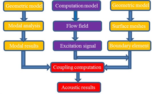
Fig. 8Boundary element model of the centrifugal pump
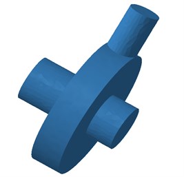
a) Boundary element model
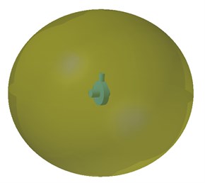
b) Field point mesh
4.2. Experimental verification of flow noises of the centrifugal pump
The measurement of external filed noises of the centrifugal pump is interfered by the motor noise, pipeline noises and background noises, resulting in a certain difficulty in the measurement accuracy. In order to verify the reliability of the numerical computation method, the noise signal within the centrifugal pump is measured by a ST70 hydrophone, whose frequency range is 50 kHz-70 kHz and sound pressure sensitivity of the receiver is –204 dB. Through the flush installation, a hydrophone is mounted directly on the wall. The sensor probe [18-21] is flush with the wall surface around measurement points, thus measuring the fluid noise within the tube directly. And the measuring point of the hydrophone is located at the model pump outlet with 4 times of the pipe diameter.
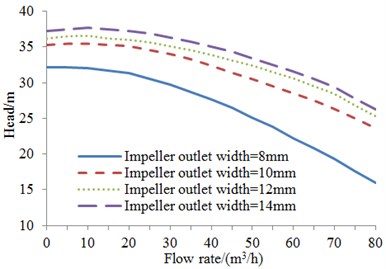
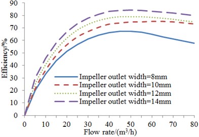
The centrifugal energy performance curves at different impeller outlet widths are obtained experimentally as shown in Fig. 9. It can be found that the pump head increases with the increase of the impeller outlet width, since the axial flow velocity is further reduced by the increasing width, thus improving the theoretical head of the pump. With the increase of impeller outlet width, the efficiency curve has larger range of high efficiency area. The efficiency has been improved and the maximum efficiency point shifts to the large flow. In addition, pump head and efficiency have a large change range when impeller outlet width increases from 8 mm to 10 mm. Pump head and efficiency have a decreased change range when impeller outlet width continues to increase.
Fig. 9Energy performance curve
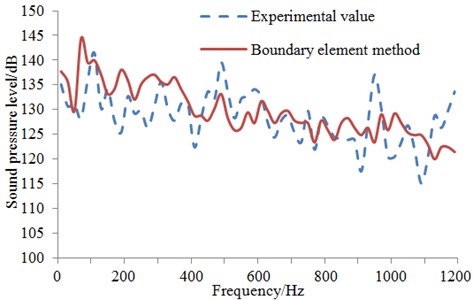
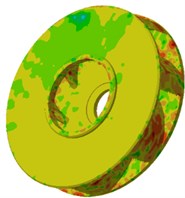
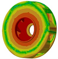
BEM is adopted to compute the internal sound field and external radiation noises of the centrifugal pump. The medium is water, density is 1000 kg/m3, acoustic wave propagation velocity is 1500 m/s, and reference sound pressure is 1×10⁻⁶ Pa. The experimental and computational results of the flow-induced noise regarding the model pump with the impeller outlet width of 10 mm are compared as shown in Fig. 10. At 1000 Hz in the figure, the experimental value is 138 dB, and BEM value is 132 dB, with the error of 4.3 %. Therefore, the experimental value has a good consistency with the computational value. The contour of sound pressure within the centrifugal pump and the contour of sound field outside the centrifugal pump are extracted and shown in Fig. 11. As shown in Fig. 11(a), the inner impeller of the centrifugal pump has relatively large sound pressure at the edge and smaller sound pressure at the center, which is consistent with the flow field distribution in Fig. 3 and Fig. 4. The impeller of the centrifugal pump has larger flow velocity and pressure fluctuation at the edge, resulting in relatively serious radiation noises. As shown in Fig. 11(b), the largest far-field radiation noise of the centrifugal pump is at the position directly facing the outlet of the centrifugal pump and radiation noises in other places are relatively weak.
Fig. 10Comparison of sound pressure level between simulation and experiment
5. Influence of impeller outlet width on the sound field of the centrifugal pump
From the above analysis, it can be seen that BEM can effectively predict the internal and external sound field of the centrifugal pump. BEM is adopted to compute the radiation noise of the centrifugal pump under different impeller outlet widths and flows. SPL at 500 Hz is exacted and shown in Table 1.
As can be seen from Table 1, in 1.0, 1.2 and 1.4, the radiation sound power of the centrifugal pump at 500 Hz is increased with the increasing impeller outlet width . and the acoustic power increase firstly and then decrease with the increasing impeller outlet In 0.8, which may be because CFD cannot accurately compute the volute force due to the complex flow field within the small flow condition. In general, the sound power of the centrifugal increases with the increase of the impeller outlet width . The model pump with the impeller outlet width of 12 mm has much greater sound power in 1.0 than in 0.8, 1.2and 1.4, while the pump with the width of 8 mm has little difference in terms of the sound power under three conditions. Just in view of sound power values under each condition, the pump with the width of 8 mm is most optimal.
Fig. 11Internal and external sound field of the centrifugal pump
a) Contour of internal sound pressure
b) Contour of external radiation noises
Table 1Sound power at characteristic frequency for different impeller outlet widths
Impeller outlet width / mm | Working conditions | |||
0.8 | 1.0 | 1.2 | 1.4 | |
8 | 29.75 | 26.373 | 42.315 | 49.33 |
10 | 76.933 | 132.32 | 56.439 | 61.21 |
12 | 57.56 | 167.395 | 62.1 | 73.52 |
14 | 55.31 | 171.32 | 63.42 | 80.13 |
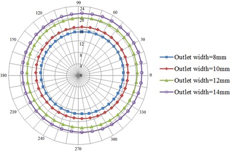
A clear directivity is in the propagation of sound. Corresponding to the sound source, different spatial points have different positions and directions, so the noise spectrums are also different. In order to obtain the circumferential distribution of the pump SPL, 36 monitor points are set at the out of the cover, which are 1000 mm away from the impeller rotation axis. The angle between any two monitor points is 10°. Noise directivity distribution of monitor points at characteristic frequency for different impeller outlet widths is shown in Fig. 12.
As shown in Fig. 12(a), in 0.8, SPL increases by 25 % with the increase of impeller outlet width from 8 mm to 10 mm; SPL has a larger change range with the increase of impeller outlet width from 10 mm to 12 mm, and increases 35 % compared with that when impeller outlet width is 10 mm; SPL increases by 17 % when impeller outlet width continues to increase to 14 mm. In as shown in Fig. 12(b), SPL increases by 20 % with the increase of impeller outlet width from 8 mm to 10 mm; when impeller outlet width increases from 10 mm to 12 mm, SPL increases by about 25 %; when impeller outlet width continues to increase to 14 mm, noise SPL increases by 13 %. In 1.2 as shown in Fig. 12(c), SPL increases by 18 % with the increase of impeller outlet width from 8 mm to 10 mm; SPL increases by 20 % with the increase of impeller outlet width from 10 mm to 12 mm; SPL increases by 11 % with the increase of impeller outlet width from 12 mm to 14 mm. In 1.41 as shown in Fig. 12(d), SPL increases by 14 % with the increase of impeller outlet width from 8 mm to 10 mm; SPL increases by 22 % with the increase of impeller outlet width from 10 mm to 12 mm; SPL increases by 10 % with the increase of impeller outlet width from 12 mm to 14 mm. As shown from the above analysis, SPL increases progressively with the increase of impeller outlet width when impeller outlet width is less than 12 mm. However, SPL decreases progressively with the increase of impeller outlet width when impeller outlet width is more than 12 mm. On one hand, the secondary flow vortex on the volute can be eliminated by the increase of the impeller outlet width, but reflux can be caused by the excessive impeller outlet width, thus increasing the static and dynamic interference effect of the impeller and volute. On the other hand, the impeller outlet width plays a significant impact on the efflux/wake phenomenon at the impeller outlet, and the wake area also enlarges with the increase of the outlet width [22-24]. Therefore, impeller outlet width has a certain range with the increase of the impeller outlet width, the pressure pulsation generated from the static and dynamic interference within the pump also strengthens, resulting in the increased noises.
Fig. 12Noise directivity distribution of monitor points under different impeller outlet width
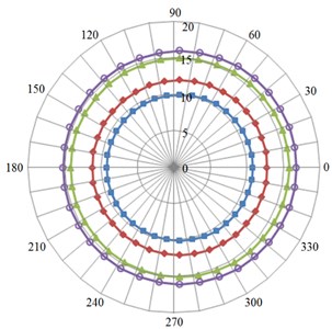
a) 0.8
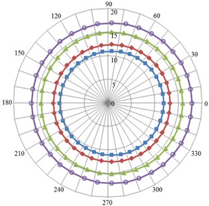
b) 1.0
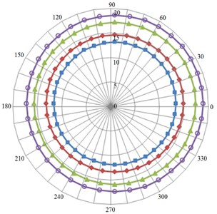
c) 1.2
d) 1.4
Compared to Fig. 9, it can be seen that: the pump energy performance is optimal and pump noise is maximum at the impeller outlet width of 14 mm, while the pump noise SPL is minimum and energy performance is poorer at the width of 14 mm. The pump energy performance is of little difference at the width of 10 mm and 14 mm, but the pump SPL is significantly smaller at the width of 10 mm. Compared with that at the width of 8 mm and 10 mm, the latter noise has smaller increasing amplitude but better energy performance than the former. As shown from the above analysis, a suitable range is presented in the impeller outlet width, so as to not only ensure the utility requirements of pump performance, but make the external field noise SPL be smaller under each flow condition. Regarding four impellers, it can be drawn from the comprehensive consideration of the centrifugal pump performance and noises that the centrifugal pump has an optimal comprehensive performance at the impeller outlet width of 10 mm.
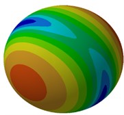
When flow is 1.0, the contours of far-field radiation noises and surface sound pressure of the centrifugal pump under different impeller widths are exacted and shown in Fig. 13 and Fig. 14, respectively. As shown in Fig. 13, the far-field radiation noise of the centrifugal pump increases to some degree with the increase of impeller outlet width, especially at the outlet of the centrifugal pump. As can be seen from Fig. 14, relatively large noise SPL always appears at the edge of the impeller when the outlet width of the centrifugal pump is from 8 mm to 12 mm, while the largest noise is at the center of the impeller when impeller outlet width is 14 mm. In addition, the contour of noises within the centrifugal pump does not show significant changes when impeller outlet width increases from 8 mm to 10 mm. With the increase of impeller outlet width from 10 mm to 12 mm, noises at the edge and outer surface of the impeller increase slightly. When impeller outlet width increases to 14 mm, noise distribution presents significant changes. The maximum noise SPL has shifted from the edge of the impeller to its center. From the above analysis, it shows that impeller outlet width has a serious impact on the radiation noise in the external field of the centrifugal pump and the internal noise of the centrifugal pump. Therefore, it is necessary to comprehensively consider many factors and confirm an optimal impeller outlet width when the centrifugal pump is designed.
Fig. 13Contour of far-field radiation noises of the centrifugal pump
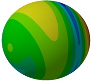
a) Outlet width = 8 mm

b) Outlet width = 10 mm

c) Outlet width = 12 mm
d) Outlet width = 14 mm
Fig. 14Contour of surface sound pressure of the centrifugal pump
a) Outlet width = 8 mm

b) Outlet width = 10 mm
c) Outlet width = 12 mm
d) Outlet width = 14 mm
6. Conclusions
LES is combined with BEM to compute and analyze the influence of impeller outlet width on the interior and external noise of the centrifugal pump, and the following conclusions can be obtained.
1) Larger pressure and flow velocity of the centrifugal pump mainly are at the edge of the impeller. When the fluid flows from the centrifugal pump, there are two obvious separation vortexes at the outlet of the centrifugal pump. The flow velocity distribution of the centrifugal pump in the horizontal plane is basically symmetric.
2) BEM is adopted to numerically compute the noise of the centrifugal pump and compared with the experimental result. According to results, their change trends are basically same and the maximum error is only 4.3 %, indicating that the computational model of flow noises of the centrifugal pump in this paper is reliable.
3) Under the same flow condition, SPL of the centrifugal pump at the characteristic frequency increases with the increase of impeller outlet width. Under the same outlet width, SPL of the centrifugal pump under is much greater than that under other flow conditions.
4) Impeller outlet width of the centrifugal pump has a serious impact on the sound field of the centrifugal pump. However, impeller outlet width of the centrifugal pump has a suitable value, which leads to smaller far-field radiation noise and surface SPL under various flow conditions. The centrifugal pump has the optimal comprehensive performance when impeller outlet width of the centrifugal pump studied in this paper is 10 mm.
References
-
Lun L. Y., Xie Y. B., Yang X. L. Lng peak-shaving proposal based on pressure energy recovery of pipe gas. Natural Gas Industry, Vol. 26, Issue 7, 2006, p. 114-116.
-
Yang J. H., Zhang X. N., Wang X. H. Performance prediction and numerical simulation of hydraulic turbine based on multi-stage centrifugal pump. Journal of Lanzhou University of Technology, Vol. 38, Issue 2, 2012, p. 42-46.
-
Wang S. L., Lun L. Y., Xie Y. B. Combined cycle system concept for the recovery of pressure energy of a natural-gas pipe network. Journal of Engineering for Thermal Energy and Power, Vol. 20, Issue 6, 2005, p. 628-631.
-
Zheng Z., Wang S. L., Wang T. Present status and prospect of fluid pressure energy recovery in natural gas transmission and distribution. Natural Gas and Oil, Vol. 27, Issue 1, 2009, p. 11-15.
-
Sun G. C., Shi W. K., Tian Y. T. Research and development in active vibration control technology. Machine Tool and Hydraulics, Vol. 3, 2004, p. 1-6.
-
Chu S., Dong R., Katz J. Relationship between unsteady flow, pressure fluctuations, and noise in a centrifugal pump. Part A: use of PDV data to compute the pressure field. Journal of Fluids Engineering, Vol. 177, Issue 1, 1995, p. 24-29.
-
Chu S., Dong R., Katz J. Relationship between unsteady flow, pressure fluctuations, and noise in a centrifugal pump. Part B: effects of blade-tongue interactions. Journal of Fluids Engineering, Vol. 117, Issue 1, 1995, p. 30-35.
-
Byskov R. K., Jacobsen C. B., Condra T., et al. Large eddy simulation for flow analysis in a centrifugal pump impeller. Advances in LES of Complex Flows Fluid Mechanics and its Applications, Vol. 65, Issue 1, 2002, p. 217-232.
-
Parrondo J. A simple acoustic model to characterize the internal low frequency sound field in centrifugal pumps. Applied Acoustics, Vol. 72, 2011, p. 59-64.
-
Langthjem M. A., Olhoff N. A numerical study of flow-induced noise in a two dimensional centrifugal pump. Part 1: hydrodynamics. Journal of Fluids and Structures, Vol. 19, Issue 3, 2004, p. 349-368.
-
Kato C., Yamade Y., Wang H. Numerical prediction of sound generated from flows with a low Mach number. Computers and Fluids, Vol. 36, Issue 1, 2007, p. 53-58.
-
Huang J. X., Geng S. J., Wu R. Comparison of noise characteristics in centrifugal pumps with different types of impellers. Acta Acustica, Vol. 35, Issue 2, 2010, p. 113-118.
-
Jiang Y. Y., Yoshimura S., Imai R. Quantitative evaluation of flow-induced structural vibration and noise in turbomachinery by full-scale weakly coupled simulation. Journal of Fluids and Structures, Vol. 23, Issue 3, 2007, p. 531-544.
-
Wei W., Xu Q., Wang L. GI/Geom/1 queue based on communication model for mesh networks. International Journal of Communication Systems, Vol. 27, Issue 11, 2014, p. 3013-3029.
-
Lin Q. Z., Zhu Q. L., Huang P. Z., Chen J. Y., Ming Z., Yu J. P. A novel hybrid multi-objective immune algorithm with adaptive differential evolution. Computers and Operations Research, Vol. 65, 2015, p. 95-111.
-
Du Z. H., Zhu Y. Y., Liu W. X. Combining quantum-behaved PSO and K2 algorithm for enhance gene network construction. Current Bioinformatics, Vol. 8, Issues 1-2013, 133, p. 137-5.
-
Chen J., Lin Q., Shen L. L. An immune-inspired evolution strategy for constrained optimization problems. International Journal on Artificial Intelligence Tools, Vol. 20, Issue 3, 2011, p. 549-561.
-
Yan Q., Yu F. R., Gong Q., Li J. Software-Defined Networking (SDN) and Distributed Denial of Service (DDoS) attacks in cloud computing environments: a survey, some research issues, and challenges. IEEE Communications Surveys and Tutorials, Vol. 18, Issue 1, 2016, p. 602-622.
-
Li J. Q., He S. Q., Ming Z. An intelligent wireless sensor networks system with multiple servers communication. International Journal of Distributed Sensor Networks, Vol. 7, 2015, p. 1-9.
-
Wei W., Yang X. L., Shen P. Y. Holes detection in anisotropic sensornets: topological methods. International Journal of Distributed Sensor Networks, Vol. 21, Issue 9, 2012, p. 3216-3229.
-
Wong K. W., Lin Q. Z., Chen J. Y. Error detection in arithmetic coding with artificial markers. Computers and Mathematics with Applications, Vol. 62, Issue 1, 2011, p. 359-366.
-
Wei W., Fan X., Song H. Imperfect information dynamic stackelberg game based resource allocation using hidden Markov for cloud computing. IEEE Transactions on Services Computing, 2016.
-
Zhu Z., Xiao J., Li J. Q., et al. Global path planning of wheeled robots using multi-objective memetic algorithms. Integrated Computer-Aided Engineering, Vol. 22, Issue 4, 2015, p. 387-404.
-
Lin Q. Z., Chen J. Y. A novel micro-population immune multiobjective optimization algorithm. Computers and Operations Research, Vol. 40, Issue 6, 2013, p. 1590-1601.
Cited by
About this article

Hengxuan Luan conceived the work that led to the submission, acquired data, played an important role in interpreting the results. Qingguang Chen revised the manuscript. Liyuan Weng performed the experiments. Yuanzhong Luan contributed materials tools and analysis tools. Jie Li designed the experiments, analyzed the data.
