Abstract
Considering the time-varying magnetic coupling stiffness caused by the component eccentricity, the parametric vibration model of the field modulated magnetic gear (FMMG) system is founded and the corresponding dynamic differential equations are deduced. The expressions of the combination resonances are worked out when the excited frequency is close to the combination frequency between the meshing frequency and the natural frequencies, and the resonance responses are discussed. The results show that the resonance amplitudes are much bigger when the excited frequency is close to the combination frequency between the meshing frequency and the natural frequency of the inner rotor torsional mode than when the frequency is close to other combination frequencies. Meanwhile, because the magnetic coupling stiffnesses are much smaller than the supporting stiffness, the resonance displacement of only one degree of freedom is always much bigger than the displacements of other degrees of freedom. The combination resonances make the stability regions of the FMMG system decrease and worsen the dynamic characteristics. All these can lay the foundation for the parameter optimization of the FMMG system.
1. Introduction
The field modulated magnetic gear (FMMG) can transmit or switch movement or force between two components by the field modulated mechanism [1-2]. Compared with the traditional magnetic gears which adopt the parallel shaft topology, FMMG adopts a coaxial topology. So, it has many advantages, such as free from lubrication, lower noise, inherent overload protection, and so on, besides the higher utilization of the permanent magnets (PMs), larger torque and higher torque density [3-4]. Also, it can be widely used in the medicine, vehicle, navigation, aerospace and other fields [5].
FMMG has got much attention of scholars because of its many virtues. Extensive researches have been carried out, such as transmission mechanism [1-3], torque characteristics [6], transmission efficiency [7], the effect of eddy current on dynamic characteristics [8], and so on. Especially the parameter optimizations for the cogging torque [9-10], the component eccentricities [11] and other dynamic characteristics are studied. All these have promoted the rapid applications of FMMG in aerospace and other fields. Meanwhile, a variety of new type of magnetic gears [12] and the permanent magnet motors [13-14] have been developed. The structural designs and the control systems of the permanent magnet motors have been discussed deeply.
Because FMMG system adopts a coaxial topology and there are manufacture and installation errors, the component eccentricities that will lead to the periodic fluctuations of torques [11] and the magnetic coupling stiffnesses are inevitable. Now, FMMG system is a typical parametric vibration system. Similar to the parametric vibration of mechanical gears system arose from the time-varying mesh stiffnesses, the component eccentricities will lead to the main resonances and the combination resonances of the FMMG system. The combination resonances will make the dynamic characteristics more complicated and must be avoided in parameter designs.
2. Parametric vibration model of the FMMG system
2.1. Time-varying magnetic coupling stiffnesses
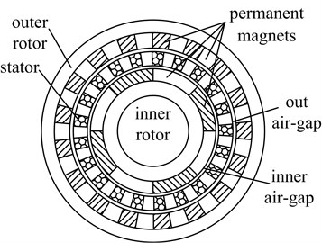
FMMG system shown in Fig. 1 consists of four basic elements: (a) the inner rotor; (b) the outer rotor; (c) the stator; (d) PMs arranged uniformly on the inner and outer rotors. The stator takes charge of modulating the magnetic fields in two air-gaps beside it in order to make the inner and outer rotors couple with equal magnetic poles.
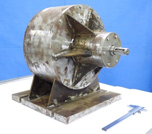
Fig. 1Topology and prototype of the field modulated magnetic gear
a)
b)
Although the high precisions of the manufacturing and installation in the FMMG system are required, the eccentricities of the inner and outer rotors that will lead to the fluctuation of the torques and the magnetic coupling stiffnesses are inevitable. So, the component eccentricities can't be ignorable. Because the effects of two rotors eccentricities on the magnetic coupling stiffnesses are similar, only the eccentricity of the inner rotor is considered in this paper.
When the eccentricity of the inner rotor is equal to 0.05 mm, the fluctuation of the moment of inertia of the inner rotor is very small and can be ignored. When the eccentricity of the inner rotor occurs, the finite element model of the FMMG system shown in Table 1 can be founded in Ansys and shown in Fig. 2. The inner rotor can turn around its translation axis, but the outer rotor and the stator are fixed. When the inner rotor rotates, the static torque characteristics and the static magnetic coupling stiffnesses of the FMMG system can be worked out by the Maxwell stress tensor [15]. Meanwhile, the time-varying magnetic coupling stiffnesses can be obtained and shown in Fig. 3(a). The fast Fourier transform (FFT) of the time-varying magnetic coupling stiffnesses can be calculated and shown in Fig. 3(b).
Fig. 2The finite element model of the FMMG system
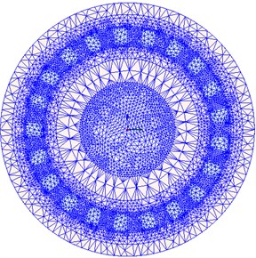
Fig. 3The time-varying magnetic coupling stiffnesses and the corresponding FFT curves
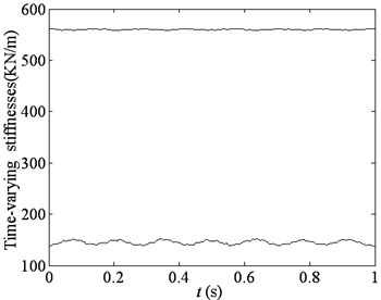
a) Time-varying magnetic coupling stiffnesses
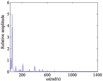
b) The fast Fourier transform curve
Table 1Parameters of example FMMG system
Number of pole pairs on the inner rotor | 4 | Number of pole pairs on the inner rotor | 17 |
Number of the ferromagnetic pole pieces | 21 | Outer diameter of the outer rotor yoke / mm | 214 |
Inside diameter of the outer rotor yoke / mm | 194 | Thickness of PMs on the outer rotor / mm | 10 |
Outer diameter of the outer airgap / mm | 174 | Inside diameter of the outer airgap / mm | 172 |
Outer diameter of the inner airgap / mm | 142 | Inside diameter of the inner airgap / mm | 140 |
Outer diameter of the inner rotor yoke / mm | 120 | Inside diameter of the inner rotor yoke / mm | 80 |
Thickness of PMs on the inner rotor / mm | 10 | Axial length / mm | 400 |
Remanence of PMs/T | 1.3 | Coercive force of PMs/KOe | 11.6 |
Fig. 3(a) shows that the tangential magnetic coupling stiffnesses among the inner rotor, the outer rotor and the stator fluctuate all. But, the magnetic coupling stiffness on the inner rotor fluctuates more sharply and the wave of the magnetic coupling stiffness on the outer rotor can be ignored.
In Fig. 3(b), is the harmonic frequency of the torque waves. There are multiple harmonic components in the tangential time-varying magnetic coupling stiffness and the main harmonic is the product of the rotary angular frequency and the number of pole pairs on the inner rotor, and will increase with the rotate speed increasing. Then, can be expressed as follows:
where is a small parameter, ; is the wave frequency of , namely, the meshing frequency, ; is the revolutions per minute of the inner rotor; is the pole pairs of PMs on the inner rotor; is the conjugate complex number of the right expression in Eq. (1), .
2.2. Parametric vibration model and dynamic differential equation
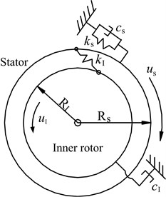
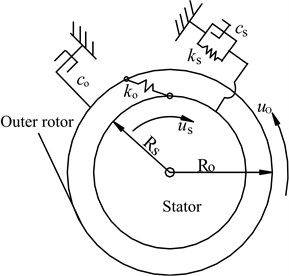
The dynamic model of the FMMG system shown in Fig. 4 consists of two subsystems, namely, the inner rotor/stator subsystem and the outer rotor/stator subsystem, when the stator is fixed. The dynamic model allows each part rotate about their central axes.
In the FMMG system, there are not frictions among the stator, the inner and the outer rotors. But, there are frictions between each part and foundation. The friction forces on all parts can be given as follows:
where , with , , , is the torsional damping coefficient among the inner rotor, the outer rotor, the stator and the foundation, respectively.
Fig. 4Dynamic model of field modulated magnetic gear system
a)
b)
Considering the eccentricities, the driving torque fluctuation of the motor, and other excitations, the torques on the inner and outer rotors always fluctuate. If the torque waves can be simplified into the cosine function, the differential equation of the parametric vibration system can be written as follows:
where , and are the torsional vibration displacements, of the stator, the inner and the outer rotors, respectively; , and are the moments of inertia of the inner rotor, the outer rotor and the stator, respectively, , , ; , and are the masses of the inner rotor, the outer rotor and the stator, respectively; , and the turning radii of the inner rotor, the outer rotor and the stator, respectively; is the average magnetic coupling stiffness along tangential direction between the inner rotor and the stator; is the average magnetic coupling stiffness along tangential direction between the outer rotor and the stator; is the torsional supporting stiffness of the stator; and are the excited frequencies of the torques on the inner and outer rotors, respectively; and are the wave amplitudes of the torques on the inner and outer rotors, respectively.
Eq. (3) can be expressed in the following matrix form:
In Eq. (4), , , , , and are the displacement vector, the mass matrix, the stiffness matrix, the incremental load vector, the damping matrix and the incremental stiffness matrix. They have the following expressions:
When the time-varying components of the magnetic coupling stiffnesses are neglected, the dynamic differential equations of the linear time-invariant system can be got in the matrix form:
Based on the linear system in the Eq. (5), Eq. (4) can be normalized into the following form:
In Eq. (6), , and are the normal displacement vector, the normal stiffness matrix and the normal load vector, which have the following expressions:
where , and are the natural frequencies of the FMMG system; is the normal shape matrix of the FMMG system; is the element on the line and the column in .
In each mode of the FMMG system, the relative displacement of only one degree of freedom (DOF) is much bigger than other degree of freedoms (DOFs), namely, , and are maxima in the torsional modes of the inner rotor, the outer rotor and the stator, respectively. The relative displacement in each mode is a difference of more than 20 times. So, and can be approximately equal to zero.
Because the damping matrix is the diagonal matrix, the elements on the primary diagonal are much bigger than other elements. So, the normal damping matrix in Eq. (6) can be simplified into a diagonal matrix as follows:
Eq. (6) can be solved by the multi-scale method. In order to balance the effects of the damping forces and the time-varying stiffnesses, the following assumptions are adopted:
where ; is the multi-scale time, .
In the actual coordinate system, the solution of Eq. (5) can be calculated by , namely:
When the excited frequency is away from the natural frequencies of the FMMG system, the following differential equations can be obtained by substituting Eq. (7) and Eq. (8) into Eq. (6), and making the same order coefficients of the small parameters on both sides of the equations equal.
Zero order:
The first order:
where , .
The solution of Eq. (9) can be expressed as:
where:
The following differential equations can be got by substituting Eq. (11) into Eq. (10):
From Eq. (12), we know that the resonances will occur when the excited frequency is close to the natural frequencies of the FMMG system. Meanwhile, the resonances will occur too when the excited frequency comes near to the combination frequencies between the meshing frequencies and the natural frequencies, namely, or ( 1, 2). These are called as the combination resonances.
3. Combination resonances
When the excited frequency on the inner rotor is close to the combination frequency between the meshing frequency and the first order natural frequency, the following assumption is introduced:
By substituting Eq. (13) into Eq. (12) and eliminating the secular terms, the following differential equations can be obtained:
The solutions of Eq. (14) can be expressed as:
where:
In Eq. (15), the components will gradually tend to zero with the time increasing. So, the zero-order analytical solution of the FMMG system in the normal coordinate system can be deduced:
where:
When the transient components are neglected, the first-order analytical solution of the FMMG system in the normal coordinate system can be obtained:
By substituting Eq (15) into Eq. (17) and substituting Eq. (16), Eq. (17) into Eq. (7), the forced responses of FMMG system in the normal coordinate system can be got:
The forced responses of FMMG system in the natural coordinate system can be calculated by the special conversion, namely, .
In the same way, the resonance responses of the FMMG system can be worked out when the excited frequency comes near to the combination frequency , or when the excited frequency is close to the combination frequency , with 1, 2.
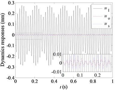
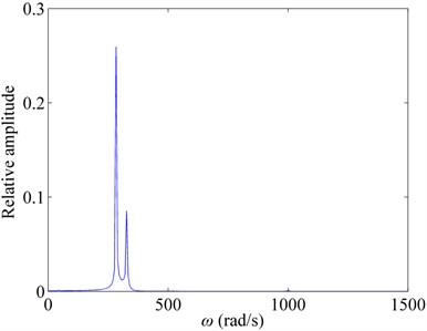
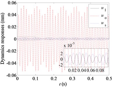
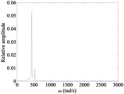
Fig. 5 shows the resonance responses and FFT curves of the example FMMG system shown in Table 2 when is close to .
Table 2Parameters of the example FMMG system
mm | mm | mm | MN/m | KN/m | KN/m | N/(m/s) | N/(m/s) | N/(m/s) | kg |
96.5 | 70.5 | 86 | 12 | 141 | 557 | 0.01 | 0.01 | 0.05 | 3.5 |
kg | kg | N·m | N·m | N·m | N·m | KN/m | rad/s | ||
2.5 | 5.6 | 40 | 170 | 1 | 5 | 5 | 210 | 4 |
From Fig. 5, we know that the dominant frequency in the combination resonances is the natural frequency, rather than the combination frequency or the meshing frequency. However, the resonance amplitudes are much bigger when is close to than when is close to , because the magnetic coupling stiffnesses are much smaller than the torsional supporting stiffness of the stator.
In the normal coordinate system, the equivalent load in each mode of the FMMG system, which is caused by torque waves, is decided by the first column of the normal shape matrix . Because the magnetic coupling stiffnesses are much smaller than the torsional supporting stiffness in FMMG system, the relative displacement of only one DOF in each order mode is much bigger than other degree of freedoms (DOFs). The normal shape matrix can be expressed by:
where , and are all smaller than 0.1, and .
Fig. 5The resonance responses of the FMMG system with ωI=ω1+ωe
a)
b)
c)
d)
From the mode characteristics of the FMMG system, the resonance amplitudes are much bigger when than when . Meanwhile, the resonance amplitudes of the inner rotor and the outer rotor will respectively reach the maximum when is respectively close to and . Similarly, the torsional displacement of the outer rotor will be much bigger than the displacement of the inner rotor when is respectively close to or .
The torque wave on the inner rotor is much bigger than the outer rotor. So the resonance arising from the combination frequency will be the main resonance source and must be drawn more attention.
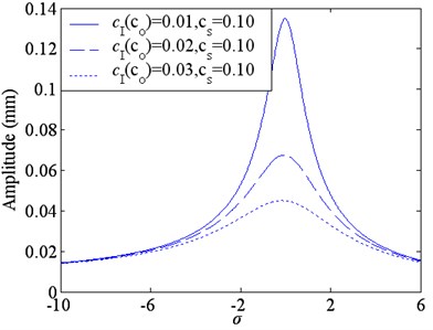
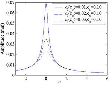
When the damping coefficients among parts increase, the resonance amplitudes will rapidly decrease. But the increasing of the damping coefficients will lower the transmission efficiency and the method isn’t desirable.
The average magnetic coupling stiffnesses are much smaller than the mechanical meshing stiffness. So, the natural frequencies are much lower than the mechanical gear systems, and the transient vibrations arising from resonances will decay very slowly. These will lead to some adverse effects, such as unstability or a certain components’ damages. In order to solve this problem, the electromagnetic coils are placed just below the surfaces of the inner and outer rotors, which can increase the electromagnetic damping and the delay of the transient displacements will be accelerated, and the dynamics of the FMMG system will be improved [16].
Fig. 6Resonance amplitude curves with the different damping coefficient
a)
b)
4. Conclusion
Considering the eccentricity will lead to the periodic variation of the magnetic coupling stiffnesses, the dynamics of FMMG system are the typical parametric vibration. Because the magnetic coupling stiffnesses are much smaller than the supporting stiffness, the resonance displacement of a certain DOF is much bigger than other DOFs, when the excited frequency is close to the combination frequency of the meshing frequency and the natural frequencies. The dominant frequency in the combination resonances is the natural frequency, rather than the combination frequency or the meshing frequency. Especially the resonance caused by the torque wave of the inner rotor is very big and must be avoided.
References
-
Atallah K., Howe D. A novel high-performance magnetic gear. IEEE Transactions on Magnetics, Vol. 37, Issue 4, 2001, p. 2844-2846.
-
Atallah K., Wang J., Howe D. A high-performance linear magnetic gear. Journal of Applied Physics, Vol. 97, Issue 10, 2005, p. N516-N516-3.
-
Rasmussen P. O., Andersen T. O., Joergense F. T., Nielsen O. Development of a high performance magnetic gear. IEEE Transactions on Industry Applications, Vol. 41, Issue 3, 2005, p. 764-770.
-
Huang Cheng-Chi, Tsai Mi-Ching, Dorrel D. G, et al. Development of a magnetic planetary gearbox. IEEE Transactions on Magnetics, Vol. 44, Issue 3, 2008, p. 403-412.
-
Frank N. W., Toliyat H. A. Gearing ratios of a magnetic gear for marine applications. Electric Ship Technologies Symposium, 2009, p. 477-481.
-
Niguchi N., Hirata K., Hayakawa Y. Study on transmission torque characteristics of a surface-permanent- magnet- type magnetic gear. IEEJ Transactions on Industry Applications, Vol. 131, Issue 3, 2011, p. 396-402-23.
-
Du Shiqin, Jiang Jianzhong, Zhang Yuejin, Gong Yu A magnetic gearing. Transactions of China Electrotechnical Society, Vol. 25, Issue 9, 2010, p. 41-46, (in Chinese).
-
Niguchi N., Hirata K., Muramatsu M., Hayakawa Y. Eddy current analysis of magnetic gear employing 3-D FEM. IEEE Conference of Electromagnetic Field Computation (CEFC), 2010.
-
Noboru N., Katsuhiro H., Masafumi Y., Masari M. Study on cogging torque reduction in a hybrid-type magnetic gear. IEEJ Transactions on Industry Applications, Vol. 130, Issue 5, 2010, p. 692-698.
-
Jian L. N., Xu G., Song J., Xue H., et al. Optimum design for improving modulating- effect of coaxial magnetic gear using response surface methodology and genetic algorithm. Progress in Electromagnetics Research, Vol. 116, 2011, p. 297-312.
-
Percebon L. A., Ferraz R., Ferreira D. L., Mauricio V. Modelling of a magnetic gear considering rotor eccentricity. IEEE International Electric Machines and Drives Conference, 2011, p. 1237-1241.
-
Wang L. L., Chau K. T. A coaxial magnetic gear with halbach permanent-magnet arrays. IEEE Transactions on Energy Conversion, Vol. 25, Issue 2, 2010, p. 319-328.
-
Jian Linni, Chau K. T., Jiang J. Z. A magnetic-geared outer-rotor permanent-magnet brushless machine for wind power generation. IEEE Transactions on Industry Applications, Vol. 45, Issue 3, 2009, p. 954-962.
-
Xiaoyong Zhu, Long Chen, Li Quan, et al. A new magnetic-planetary-geared permanent magnet brushless machine for hybrid electric vehicle. IEEE Transactions on Magnetics, Vol. 48, Issue 11, 2012, p. 4642-4645.
-
Xiaoming Yuan, Xiuhong Hao, Bing Du, Lijie Zhang Dynamic model of field modulated magnetic gear system. Journal of Vibroengineering, Vol. 16, Issue 1, 2014, p. 477-486.
-
Frank N. W., Pakdelian S., Toliyat H. A. Passive suppression of transient oscillations in the concentric planetary magnetic gear. IEEE Transactions on Energy Conversion, Vol. 26, Issue 3, 2011, p. 933-939.
About this article
This project is supported by Natural Science Foundation of China (51205341, 51275438), Research Program of Natural Science at Universities of Hebei province (Q2012032), Joint Fund of Specialized Research Fund for the Doctoral Program of Higher Education and Hebei Provincial Education Office (20121333120004).
