Abstract
The aim of this study is to find a rapid and accurate method for wing flutter prediction in the early stage of aircraft design. A method using the concept of equivalent stiffness is presented for the modal and flutter analysis of a wing. The concept of equivalent stiffness method is that the stringer-stiffened panels in wing structures are replaced by unstiffened panels with the same stiffness, and accordingly the complicacy of the finite element (FE) modeling for wing structures can be reduced substantially. The key of the method is on computation of the stiffness matrices of the unstiffened panels with the equivalent mechanical properties of the stringer-stiffened panels. A regional aircraft wing is used for a case study to verify the accuracy of this method. Both the detailed FE model and the FE model with equivalent stiffness for the wing structure are created and analyzed in MSC.Patran/Nastran. The numbers of elements and degrees of freedom in the FE model with equivalent stiffness are reduced to one-tenth of those in the detailed wing FE model. The complicacy of the detailed FE modeling of the wing structure, such as modeling stringers and handling irregular surface, is avoided in the FE model with equivalent stiffness. The results show that the natural frequencies, mode shapes and flutter speed from the two models are in a good agreement. Satisfactory accuracy and rapid modeling of the FE model with equivalent stiffness make it suitable for wing flutter prediction in conceptual and preliminary aircraft design.
1. Introduction
Flutter is a dynamic instability of a flight vehicle associated with the interaction of aerodynamic, elastic and inertial forces [1]. Because flutter is usually destructive, it must be completely eliminated by design or prevented from occurring within the entire flight envelope. The requirement for flutter prevention has large impacts on the stiffness and mass distribution of wing. Therefore, it is essential to take flutter into account in the early stage of aircraft design, especially for the high aspect ratio flexible wing design.
Wing flutter prediction involves the aerodynamic forces applied on the wing and the dynamic characteristics such as natural frequency and mode shape of the wing structure. A reasonably accurate analysis model for the wing dynamic characteristics is critical for flutter prediction. In general, there exists three kinds of methods for structural dynamic analysis the equivalent beam model, the equivalent plate model, and the finite element method.
For the equivalent beam model, the wing structure is simplified into a beam [2]. It was widely used in flutter analysis of high aspect ratio wings in the past due to its simplicity and high computation efficiency. But good engineering experience is needed to create such models. In addition, its accuracy is limited. Furthermore, the equivalent beam model can hardly be applied to the wing with novel configurations and materials.
For the equivalent plate model, the wing planform and structure are divided into a set of trapezoidal plates using the classical plate theory and polynomial Ritz approximation. The trapezoidal plates have the same mechanical properties as those in the original wing structure. This method was introduced by Giles [3, 4], further developed by Livne [5]. The equivalent laminated plate solution (ELAPS) program was applied to the high speed civil transport (HSCT) for static, modal and flutter analysis [6]. The equivalent plate model was also used for the sensitivity analysis of wing parameters on static aeroelastic and flutter by Eldred [7]. In general, the equivalent plate model takes wing planform into account and can predict flutter with better accuracy for the wing with low aspect ratio.
The finite element (FE) method can be considered as a versatile method and has better prediction accuracy for structural analysis. But its disadvantage is that the detailed FE modeling of wing structures is very complicated and time-consuming. The complicacy mainly roots in the detailed FE modeling of stringer-stiffened panel in wing structures. As a result, the standard FEM are hardly used to predict flutter of wing in the early stage of aircraft design.
One solution to deal with the complicacy of FE modeling above is to simplify the FE model by using the equivalent stiffness method. In the equivalent stiffness method, the stringer-stiffened panel of aircraft structure is replaced by a clean panel (unstiffened panel) which has the same mechanical properties (same stiffness). In this way, the FE modeling for stringer-stiffened panel is simplified, and consequently the complicacy of the FE modeling for wing structure is reduced substantially.
The concept of the equivalent stiffness has been studied in aircraft structural analysis by many authors. For example, the equivalent stiffness method was applied to buckling load analysis of grid stiffened composite cylinders by Kidane [8], used for static analysis of a blended wing body aircraft by Bradley [9], utilized for optimization of composite wing structures by Zhao [10], applied to strength and buckling analysis for mass estimation of primary structure by Wenzel [11]. Their studies indicate that the accuracy of the FE modeling with the equivalent stiffness is quite satisfactory. But there is still lack of accuracy verification of FE model with the equivalent stiffness for wing modal and flutter analysis.
In this study, the FE modeling with the equivalent stiffness is applied to analysis of the wing modal and flutter. The computation accuracy will be verified by comparisons between results from the detailed FE modeling and those from the FE modeling with the equivalent stiffness. It is expected that the FE modeling with the equivalent stiffness has satisfactory accuracy and can be used for wing flutter prediction in the early stage of aircraft design.
2. Equivalent stiffness method
2.1. Concept of equivalent stiffness
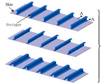
The stringer stiffened panels as shown in Fig. 1(a) are widely used in thin-walled or shell structures which are major components in aircraft structure. The existence of the stiffener causes the equivalent neutral surface offsetting out of skin’s middle surface, improving the local bending stiffness. The FE modeling for wing structure with complex stringer-stiffened panels is burdensome and time consuming. The aim of the equivalent stiffness method is to simplify FE modeling of the stringer-stiffened panels. The idea is that the stringer-stiffened panel is modeled by a clean panel with the same stiffness properties. The stiffness matrices of the clean panels are derived from the panels with specific stringer profiles.
The process of the equivalent stiffness method is depicted in Fig. 1, and is briefly described as follows:
1) The stiffener is divided into a series of strips, as shown in Fig. 1(b).
2) The stiffness coefficients of each strips and skin are calculated according to classical lamination theory.
3) The anisotropic equivalent stiffness matrices (ABD-matrices) are obtained by sum of the stiffness coefficients of strips and skin.
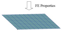
4) The finite element properties of the clean panels are assigned with the equivalent stiffness matrices from the above step.
In the following subsections, the detailed procedure will be presented.
Fig. 1Modeling approach of different stiffened panels: a) various stiffened panels; b) profile of I-Shape stiffener; c) equivalent stiffness matrix; d) shell elements
a)
b)
c)

d)
2.2. Coefficients of equivalent stiffness
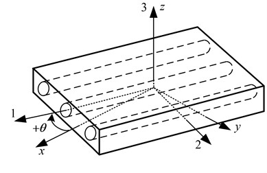
As shown in Fig. 2, the 123 coordinates are defined as the principal material coordinates and the global coordinates are the coordinates. Because the load on aircraft wings and fuselages are mostly in-plane, only in-plane stresses of , and need to be considered. For a typical layer of orthotropic material, the stress-strain relations [12, 13] reduce to:
where the , , , and are the reduced stiffnesses for a plane state in the 1-2 plane. , and are strains in the 1-2 plane. Eq. (1) is reduced from a 6×6 matrix of three-dimensional stress-strain equation.
Fig. 2Rotation of principal material axes from xyz axes
Usually, the principal material coordinates do not coincide with the coordinates directions geometrically natural to the solution of the problem. For example, a laminate includes different laminae at different orientations. Thus stress-strain in principal material coordinates must be transformed to those in the global coordinates. The stress-strain relations for a lamina of arbitrary orientation is:
where the matrix denotes that the transformed reduced stiffness which takes the place of the reduced stiffness, .
According to the classical lamination theory, the skin and strips stiffnesses can be calculated. The load-deformation relations of a laminate is:
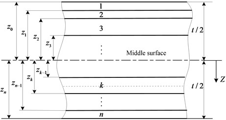
where and denote the resultant forces per unit width, and the shear forces per unit width. and denote the bending moments per unit width, and the twisting moment per unit width. , and represent the strains of the middle surface, , and the curvatures of the middle surface. , and represent the extensional and bending stiffness respectively, given by:
where and are defined in the laminate geometry of Fig. 3.
Fig. 3Geometry of an n-layered laminate
2.3. Equivalent neutral surface for stiffened panel
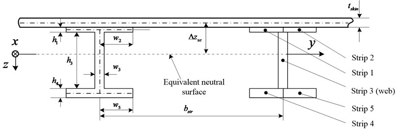
The bending stiffnesses calculation of the skin and strips are referred to the position of the neutral surface. Usually the neutral surface of stringer-stiffened panel is not a flat plane, but a curved surface, as shown in Fig. 4. In the region of stringer-stiffened the neutral surface is offset out off skin’s middle surface, but in the region between two stringers the neutral surface still coincides with the skin’s middle surface. Thus it is difficult to determine the constitutive relation between the reference neutral surface and discrete strips. An equivalent neutral surface is defined to replace the actual neutral surface, as demonstrated in Fig. 4.
Fig. 4Equivalent neutral surface
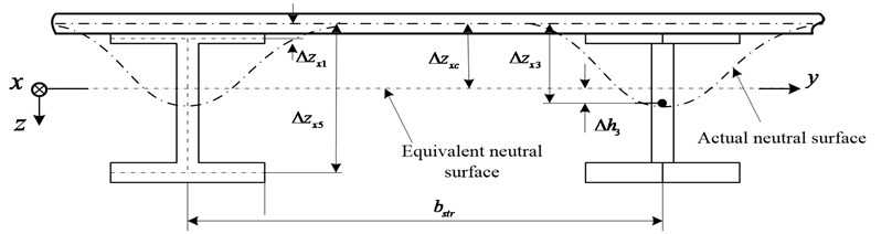
In Fig. 4, denotes the distance from skin’s middle surface to the equivalent neutral surface. denotes the distance from skin’s middle surface to each strip’s middle surface. denotes the distance from equivalent neutral surface to each strip’s middle surface.
The plane is assumed on the equivalent neutral surface. For the pure bending, the resultant force on combined-section along the direction is zero [14], that is:
where is the elastic modulus of isotropic material. For , and it can be rewritten as:
thus the can be calculated by:
2.4. Transformation of stiffness
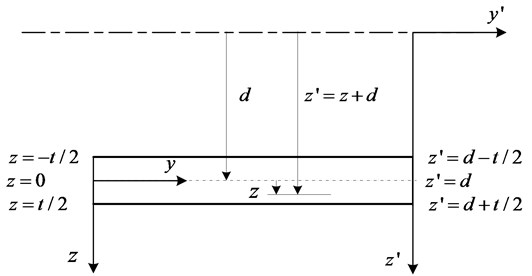
Because the equivalent neutral surface of stringer-stiffened skin is offset from middle surface of skin, as shown in Fig. 2,
Fig. 5The relation of skin’s middle surface and surface parallel to the middle surface
The stiffness of skin and stringers must be transformed. The relation equations of skin stiffness referring to skin’s middle surface and equivalent neutral surface can be given by [15]:
where , and represent the transformed extensional, coupling and bending stiffness respectively. The parameter denotes the distance between skin’s middle surface and surface parallel to the middle surface, as shown in Fig. 5.
2.5. Stiffness matrix of skin
The skin and stiffeners can be regarded as an isotropic layer for metal wing. For the single isotropic layer there is no coupling effect between extension and bending. As a result, the relations between the resultant forces and moments and the strains [12] can be written as:
where is the Poisson ratio. and are given by:
Because the stringers axis are parallel to coordinate direction, the skin bending stiffness in the plane is increased. Substituting Eq. (8) into Eq. (9), the transformed skin stiffness matrix can be rewritten as:
2.6. Stiffness matrix of stringer
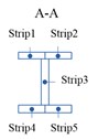
A stringer-stiffened panel with “I” profile is used as a baseline for calculation of stiffness matrix of stringer, and is depicted in Fig. 6. The stringer is divided into five strips. The parameter denotes the strip width, the strip height, the stringer pitch. The other profiles of stringer can be derived from I-shape stringer by setting the strip parameters. For example, when the width and height parameters of the strip 4 are set to 0, the stringer profile becomes J-shape. When the width and height parameters of the strip 4 and 5 are set to 0, the stringer profile becomes T-shape. Also, a Z-shaped stringer profile is obtained if the width and height parameters of the strip 2 and 4 are set to 0. Therefore, the stiffened panels with various profiles of stringer can be rapidly generated by setting the parameters of strips.
It is assumed that direction is parallel to the stringer axis, is perpendicular to stringer web, and is positive downward as shown in Fig. 6. Load distributions on the skin and stinger depend on their stiffness. The axial force and bending moment applied on stringer per unit width equal to the sum of all the force axial and bending moment on every strips respectively, and is stated as follows:
The load-deformation relations in the form of matrix becomes:
Fig. 6The typical profile of stiffened panel
According to the manner of stringers connecting to the skin, the calculation of the extensional and shear stiffness of a stringer strip depends on whether it is attached to the skin or not. For metal stringer stiffened panels, the stringers are connected to skin by riveting, thus the extensional and shear stiffness of the stringer strips can be ignored. For composite stringer stiffened panels, the stringers and skin are integrated. So the extensional and shear stiffness of the stringer strips attached to the skin should be taken into account.
The twist stiffness of the stringer should also be considered, and is given by:
where is the shear modulus, and is the torsional stiffness for each strip.
2.7. Assembly of stiffened panel stiffness matrix
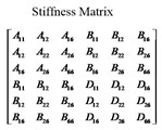
The equivalent stiffness matrix of unstiffened panel can be assembled from the skin and stringer stiffness matrices, and is stated as the following:
In assembling operations, the term of the coupling stiffness is eliminated. In other words, the matrix above is zero.
3. Case study
3.1. FE modeling of a wing structure
The wing modal and flutter prediction of a regional aircraft wing is used as an example to verify the accuracy of the FE model with the equivalent stiffness or namely equivalent FE model. The aspect ratio of the wing is 10.0, the wing area is 95.75 m2, the sweep angle at 1/4 chord is 24.5°, and thickness ratio at wing root is 0.14.
The detailed finite element model and equivalent FE model of the wing are created and meshed in MSC.Patran and shown in Fig. 5. The same load cases and boundary conditions are applied on the two models. The structural material used in both models is aluminum alloy that has an elastic modulus of 70 GPa, the density of 2.7×10³ kg/m3, and the Poisson’s ratio of 0.3. The detailed FE model for the wing consists of 58,065 elements with 302,916 degrees of freedom, as shown in Fig. 7(a). The detailed FE modeling of T-shape stringer-stiffened panel is also shown in Fig. 7(a). The corresponding equivalent FM model is shown in Fig. 7(b), and has 6,205 elements with 26,364 degrees of freedom which are roughly one-tenth of those in the detailed wing FE model.
Fig. 7Two finite element models of the wing: a) the detailed FE model; b) the equivalent FE model
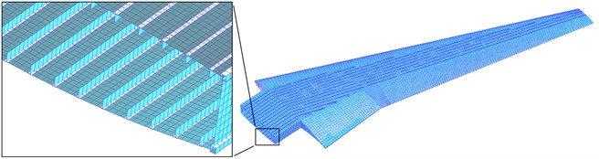
a)
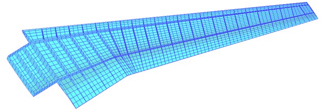
b)
Comparisons between the above two FE models reveal the significance of the equivalent stiffness method. The complicacy of the detailed FE modeling of wing structure roots in that a lot of detailed structures needed to be dealt with. For instances, the stringers are usually located to be parallel to the rear spar in the wing structure. Some of stringers intersect with the front spar, which causes some triangular or pentagonal surfaces. Meshing these surfaces needs manual operations. This impedes automatic meshing and parametric FE modeling in aircraft pre-design stage. In the equivalent stiffness method, the FE modeling for stringers and handling irregular surface are avoided, and automatic meshing and FE parametric modeling can be implemented without difficulty. Furthermore, modeling various stringer stiffened skins is straightforward by changing the stringer profile in the equivalent FE model, without recreating the FE model.
3.2. Modal analysis
In general, the natural frequencies and modes shapes of wing provide enough information for flutter analysis. The natural frequencies and mode shapes from the detailed FE model (DFEM) and the equivalent FE model (EFEM) are computed in MSC.Nastran, and the results are listed in Table 1.
Table 1Result comparisons of modal analysis
Number | Mode shape | Natural frequency | Error / % | |
DFEM / Hz | EFEM / Hz | |||
1 | 1st vertical bending | 3.051 | 3.043 | –0.26 |
2 | 2nd vertical bending | 9.620 | 9.605 | –0.16 |
3 | 1st horizontal bending | 13.653 | 13.789 | 1.00 |
4 | 3rd vertical bending | 20.363 | 20.135 | –1.12 |
5 | 1st torsion | 27.764 | 28.991 | 4.42 |
6 | 4th vertical bending | 34.398 | 34.390 | –0.02 |
7 | 2nd horizontal bending | 44.783 | 45.932 | 2.57 |
8 | 2nd torsion | 46.619 | 48.406 | 3.83 |
9 | 5th vertical bending | 50.895 | 51.049 | 0.30 |
10 | 3rd torsion | 65.719 | 67.350 | 2.48 |
From Table 1, all mode shapes of equivalent FE model are in good agreement with those of detailed FE model. The differences of the natural frequencies predicted by the two FE models are quite small within 5 %.
3.3. Flutter analysis
Flutter speed is an important performance index in aircraft design. If flutter speed can be reliably and rapidly predicted in early phase of aircraft design, it is helpful for designers to find the optimal aircraft configuration and structural layout. In this study, the flutter speeds of two FE models for the wing are predicted by p-k method [16, 17] in MSC.Nastran.
The first 10 modes for two FE models listed in Table 1 are selected for flutter analysis. The results of the velocity-damping and velocity-frequency diagrams are shown in Figs. 6 and 7 respectively.
Table 2Comparison of flutter analysis results from two FE models
Method | Flutter speed / (m∙s-1) | Frequency / Hz |
DFEM | 398.0 | 14.981 |
EFEM | 405.4 | 15.586 |
Relative difference / % | 1.86 | 4.04 |
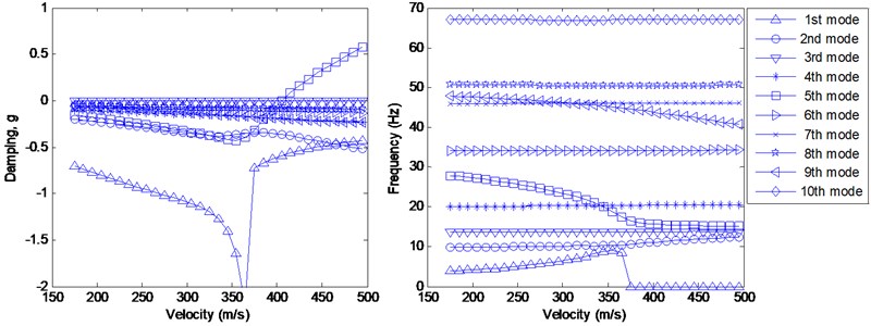
According to Fig. 8 and 9, it is quite apparent that the curves of the velocity-damping and velocity-frequency from the two FE models are in a good agreement.
As shown in Table 2, the relative differences of the flutter speed and frequency from two FE models are pretty small, only 1.86 % and 4.04 % respectively.
Fig. 8Flutter analysis from the detailed FE model
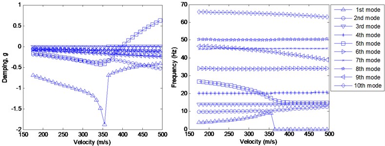
Fig. 9Flutter analysis from the FE model with equivalent stiffness
4. Conclusions
This paper has presented a method for wing modal and flutter analysis using the FE model with equivalent stiffness. The aim of the method is to reduce complicacy of the detailed FE modeling of wing structure. The accuracy of the method was verified by the case study of a regional aircraft wing. The conclusions are drawn as follows:
1) The FE modeling for stringers and handling irregular surface are avoided by using the FE model with equivalent stiffness. The number of elements and degrees of freedom in the equivalent FE model are reduced to one-tenth of those in the detailed FE model of the wing.
2) The wing natural frequencies and mode shapes from equivalent FE model well match those from detailed FE model.
3) The flutter speed predicted by the equivalent FE model is very close to that by the detailed FE model.
4) Satisfactory accuracy and rapid modeling of the equivalent FE model make it suitable for wing flutter prediction in conceptual and preliminary aircraft design.
In our future study, it is planed that the FE model with equivalent stiffness will be applied to wing multidisciplinary analysis and optimization in the early phase of aircraft design.
References
-
Hodges D. H., Pierce G. A. Introduction to structural dynamics and aeroelasticity. Second Edition, Cambridge University Press, New York, 2011.
-
Lee U. Dynamic continuum modeling of beamlike space structures using finite-element matrices. AIAA Journal, Vol. 28, Issue 4, 1990, p. 725-731.
-
Giles G. L. Equivalent plate analysis of aircraft wing box structures with general planform geometry. NASA-TM-87697, 1986.
-
Giles G. L. Further generalization of an equivalent plate representation for aircraft structural analysis. NASA-TM-89105, 1987.
-
Livne E., Navarro I. Nonlinear equivalent plate modeling of wing-box structures. Journal of Aircraft, Vol. 36, Issue 5, 1999.
-
Stone S. C., Henderson J. L., Nazari M. M. Evaluation of equivalent laminated plate solution (ELAPS) in HSCT sizing. 2000.
-
Eldred L. B., Kapania R. K., Barthelemy J. Sensitivity analysis of aeroelastic response of a wing using piecewise pressure representation. AIAA, 1993, p. 93-1645.
-
Kidane S., Li G., Helms J. Buckling load analysis of grid stiffened composite cylinders. Composites Part B: Engineering, Vol. 34, Issue 1, 2003, p. 1-9.
-
Bradley K. R. A sizing methodology for the conceptual design of blended wing body transports. George Washington University, 2004.
-
Zhao Q., Ding Y. L., Jin H.B. A layout optimization method of composite wing structures based on carrying efficiency criterion. Chinese Journal of Aeronautics, Vol. 24, 2011, p. 425-433.
-
Wenzel J., Sinapius M., Gabbert U. Primary structure mass estimation in early phases of aircraft development using the finite element method. CEAS Aeronautical Journal, Vol. 3, 2012, p. 1-10.
-
Jones R. M. Mechanics of composite materials. Second Edition, Taylor & Francis Group, Philadelphia, 1999.
-
Kaw A. K. Mechanics of composite materials. Taylor & Francis Group, Boca Raton, 2006.
-
Timshenko S., Woinhowsky-Krieger S. Theory of plates and shells. Second Edition, McGraw-Hill Book Company, New York, 1959.
-
Li S. L. A handbook of composite materials. Aviation Industry Press, Beijing, 1988, (in Chinese).
-
Rodden W. P., Harder R. L., Bellinger E. D. Aeroelastic addition to Nastran. NASA Contractor Report 3094, 1979.
-
MSC.Nastran Aeroelastic Analysis User’s Guide, (Version 68).
About this article
