Abstract
The design of dynamic torsional vibration dampers of piston internal combustion engines is generally based on the principle of a dynamic damper with one degree of freedom in which the coupling of the seismic mass of the damper to the basic dynamic system is realized by a two-parameter parallel rheological model. With known realizations of this principle, it is usually difficult to achieve the optimum value of the respective damper parameters determined from the computational models, which is particularly true for optimal damping values. A dynamic torsional damper, based on the series arrangement principle of the elastic and damping element, offers better design options to achieve the optimum parameters of both the elastic and damping elements.
1. Introduction
For dynamic torsional vibration dampers in large engines (see Fig. 1 on the left), the optimal parameters of the elastic and damping coupling of the seismic ring can be ensured by suitable design, since the flexible parts are made of metallic elements and the lubricating oil is used as the damping medium. The optimum parameters of such a torsional damper remain stable even during a long-term engine operation.
In smaller engines for commercial vehicles or tractors, the viscoelastic coupling of the damper ring is usually realized with a rubber spring, usually made of natural rubber (see Fig. 1 on the right). The disadvantages of rubber dampers are, in particular, insufficient damping properties of the rubber spring compared with the optimal values resulting from the respective computational models [1-4]. For internal combustion engines with higher power output, the design of rubber torsional dampers is difficult because the dissipated power in the rubber elements can reach up to hundreds of watts, and insufficient heat removal would cause their destruction. Classical viscous torsional dampers [2, 3] have a relatively low damping effect.
The design of a torsional damper with a serial arrangement of the elastic and damping element uses a viscous torsional damper [2-4], whose housing is coupled by a torsion spring to the basic crank mechanism of the engine.
Fig. 1Torsional vibration damper based on parallel viscoelastic coupling of seismic mass. a) torsional vibration damper Geislinger for large engines; b) rubber damper for commercial vehicle engines
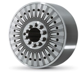
a)
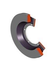
b)
2. Optimization strategy to determine the dynamic damper optimal parameters
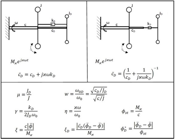
The characteristic properties of a dynamic torsional vibration damper with 1 degree of freedom and coupling of its seismic mass by a viscoelastic 2-parameter model (Kelvin model) are presented in sources [2-4], wherein usually a harmoniously excited basic system with 1 degree of freedom is considered, see Fig. 2 on the left. A viscous damper [3] may be considered a special example of a damper of the above-mentioned type, and the behaviour, therefore, can be easily derived from the condition of zero stiffness of the viscoelastic coupling.
The optimization strategy in the design of dynamic vibration dampers with 1 degree of freedom is based on the existence of the so-called fixed points of the amplitude frequency responses [2, 4]. These are the points of the amplitude frequency responses of the basic system which are determined independently of the damping coefficient value of the damper. In the first stage of the optimization, the ordinates of the fixed points are determined and the optimum value of the tuning of the damper is obtained. In the second stage, the (approximate) optimal degree of damping of the damper can be determined. Only with a viscous damper [2], the method described leads to a mathematically accurate solution to the problem.
In addition to the common types of dynamic torsional dampers mentioned, it is also possible, in this way, analyse the properties of a damper coupled through a viscoelastic 2-parameter model in a series arrangement. This viscoelastic model (the so-called Maxwell model) was previously considered to be particularly suitable for research on creep and flow processes, see Fig. 2 on the right.
Fig. 2Basic principle of dynamic torsional vibration dampers with coupling by means of viscoelastic 2-parameter models and definition of dimensionless quantities (coupling in parallel arrangement on the left, coupling in series arrangement on the right)
Optimization of the 1-degree-of-freedom torsional vibration damper with coupling by the Maxwell rheological model is performed in the case of the 1-degree-of-freedom basic system.
The complex amplitudes of the members of the system in Fig. 2 can be determined from equations:
For an easier comparison of the solution results, it is advantageous to introduce the dimensionless quantities according to Fig. 2, which are the same for both cases of the viscoelastic 2-parameter couplings: relative damper size , tuning of the damper against the basic system , damping ratio , ratio of the excitation angular frequency to the natural angular frequency of the basic system , static amplitude , magnification function of the torsional moment in the basic system and in the viscoelastic coupling of the damper , etc.
Using the dimensionless parameters according to relationships in Fig. 2 the following equation for the amplitude-frequency characteristic of the basic system is given:
The amplitude frequency responses of the basic system according to (2) are set for a given relative damper size and a given tuning of the damper by two fixed points A, B, irrespective of the value of the damping ratio . Examples of these amplitude frequency responses are shown in Fig. 3.
Fig. 3Fixed points of the amplitude frequency responses of the basic system with dampers using the series viscoelastic coupling (μ= 0.25, w= 1)
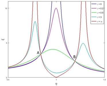
The coordinates of these points can be most easily represented as intersections of the amplitude frequency responses (2) at extreme values of the damping ratio 0 and . For 0, which physically corresponds to a damper separated from the basic system, follows:
and for , which from a physical point of view corresponds to the connection of the element to the elastic element , results:
The value of the damper tuning affects the magnitude of the ordinates of the fixed points A, B, the goal of the solution being to minimize these ordinates.
Similar to the damper with a parallel viscoelastic coupling [2] are, in this case with an optimal tuning of the damper , the ordinates of the fixed points A, B minimal and at the same time, they have the same size. If the absolute values of the relative amplitudes according to (3) and (4) are equated to one another, then after conversion for the optimum tuning follows:
and for the ordinates of the fixed points corresponding to the optimum tuning of the damper, the relationship is obtained:
The values of the damping ratio corresponding to the horizontal tangent of the amplitude frequency response at point A or B do not differ too much, which is in line with expectations. From a practical point of view, the arithmetic mean of both values can then be considered and the optimal degree of attenuation expressed by the following relationship:
3. Comparison of the basic behaviour of vibration dampers with 1 degree of freedom
A comparison of the dependencies for the optimal tuning of both dampers with a parallel and serial viscoelastic 2-parameter coupling is shown in Fig. 4.
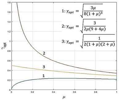
The optimum damping ratio waveforms for different types of torsional vibration dampers are shown in Fig. 5.
Fig. 4Optimum values of the damper tuning as a function of μ (1 – damper with 2-parameter parallel coupling, 2 – damper with 2-parameter series coupling)
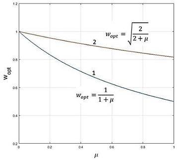
Fig. 5Optimal values of the damping ratio at optimal damper tuning (1 – damper with 2-parameter parallel coupling, 2 – damper with 2-parameter series coupling, 3 – viscous damper)
4. Application of a torsional vibration damper with serial viscoelastic coupling
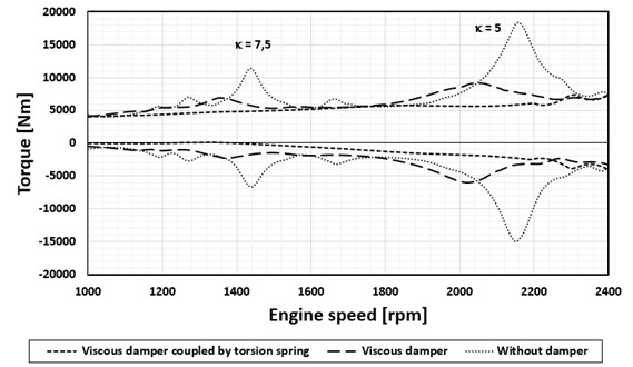
The torsional vibration damper utilizing the principle of a viscoelastic serial coupling was applied to a V10 diesel engine for heavy trucks. The design of this damper uses a viscous torsional damper, whose housing is coupled by a torsion spring to the crank mechanism of the engine. Fig. 6 shows the waveforms of the maximum values that are evaluated from calculated periodic signals of the torque at the crank pin by the flywheel [5-7]. The results of the computational model were subsequently verified by tensometric measurement.
Fig. 6V10 diesel engine, maximum torque values in the crankpin by the flywheel (calculation, validated by means of strain gauge measurements)
5. Conclusions
With known torsional vibration dampers based on the principle of seismic ring coupling by a flexible and damping element in a parallel arrangement, it is usually difficult to achieve the optimum value of the respective damper parameters determined from the computational models, which is particularly true for optimal damping values. This is the main problem with the rubber torsional dampers where in addition difficulties with heat dissipation in the rubber arise. As an alternative, therefore, many larger engines use viscous dampers [8-10]. Their damping efficiency is, however, relatively low. A better solution in these cases can be a damper with the serial viscoelastic coupling, realized by a viscous torsional damper, whose housing is coupled by a torsion spring to the crank mechanism of the engine. The advantages of such a solution compared to a simple viscous torsional damper were illustrated on a V10 diesel engine.
References
-
Genta G. Vibration of Structures and Machines. Springer-Verlag, New York, 1993.
-
Nestorides E. J. A Handbook on Torsional Vibration. Cambridge University Press, Cambridge, 1958.
-
Heisler H. Advanced Engine Technology. 1st Edition. Arnold, Oxford, 2002.
-
Lewis F. M. The extended theory of the viscous vibration damper. Journal of Applied Mechanics, Vol. 22, 1955, p. 515-552.
-
Tůma J. Vehicle Gearbox Noise and Vibration: Measurement, Signal Analysis, Signal Processing and Noise Reduction Measures. John Wiley, Chichester, 2014.
-
Gupta A. Numerical Methods using MATLAB. Springer-Verlag, New York, 2014.
-
Porteš P., Kučera P., Píštěk V., Fojtášek J., Zháňal L. Modern tools for vehicle development. Engineering Mechanics, Vol. 2017, 2017, p. 54-57.
-
Kučera P., Píštěk V. Testing of the mechatronic robotic system of the differential lock control on a truck. International Journal of Advanced Robotic Systems, Vol. 14, Issue 5, 2017, p. 1-7.
-
Prokop A., Řehák K. Virtual prototype application to heavy-duty vehicle gearbox concept. Engineering Mechanics, Vol. 2017, 2017, p. 810-813.
-
Drápal L., Šopík L., Vopařil J. Investigation of torsional vibration of unconventional crank train. Vibroengineering Procedia, Vol. 7, 2016, p. 31-36.
About this article

This work is an output of the internal BUT research Project Reg. No. FSI-S-17-4104.
