Abstract
A new vibration testing method is introduced to measure three-axis vibration of harmonic drives used in industrial robots. To simulate the working state of industrial robots, a harmonic drive loading device was designed. In the case of loading, the vibration of a harmonic drive in three axes was measured. Experimental data was used to evaluate the vibration performance, analyze the vibration characteristics of the harmonic drive, and determine the cause of the vibration abnormality. The research results showed that the presented measuring method is helpful to monitor the vibration performance of harmonic drives, and control the quality of the product.
1. Introduction
Harmonic drives have been widely used in the field of industrial robots because of the advantage of high transmission accuracy, transmission ratio etc. As the main vibration form of harmonic drives [1], torsional vibration directly affects the movement accuracy of the robot. Therefore, it is important to improve transmission precision and vibration resistance of harmonic drives by studying the vibration characteristics of harmonic drives in the case of loading [2]. In addition to torsional vibration, the axial and radial vibrations of harmonic drives also directly influence the performance of the robot and other precision machinery. On vibration test of harmonic drives, Tao Xueheng [3] established a harmonic drive torsional vibration test device, and measured the natural frequency of the transmission system; Xin Hongbing [4] set up a device to test the nonlinear dynamic characteristics of torsional vibration, but without considering the actual load. Zhang Youlin [5] introduced a comprehensive testing method of harmonic drives under loading conditions, analyzed the impact of various processing errors on torsional vibration. Cheong Yoo [6], In-Gyu Park [7] measured the natural frequencies of harmonic drives, and tested the radial and axial vibration characteristics respectively with two acceleration sensor. Hongbo Liao [8] designed a control model with FIR filter and speed feedback to suppress the torsional vibration of harmonic drives.
Although there have been a lot of researches about the vibration of harmonic drives, most of the existing vibration test methods of harmonic drives are only used to measure torsional vibration. Without axial and radial vibration test, the influence of the various parts on three-axis vibration is unclear. The test conditions are different from the actual work conditions of harmonic drives, so the experimental data cannot accurately reflect the vibration performance of harmonic drives. Therefore, this paper will introduce the three-directional vibration test method of harmonic drives. To simulate the working condition of an industrial robot joint, an inertial load was designed and attached to the harmonic drive. The radial, circumferential and axial vibration acceleration value of harmonic drives were tested under different speed. The experimental data was used to evaluate vibration performance comprehensively, determine the cause of abnormal vibration and explore the influence of different parts on three-axis vibration.
2. Vibration test method
2.1. Test process
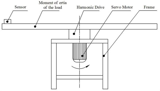
A sketch of three-axis vibration measuring device is shown in Fig. 1. To simulate the working state of harmonic drives, the load rotating arm is installed at the output end of a harmonic drive. The input of the harmonic drive is connected with a servo motor providing steady and adjustable driving speed. MTE8 three-axis wireless vibration acceleration sensor was installed on the load arm at 0.55 meters from the center of rotation, and measured the circumferential(torsional), axial and radial vibration acceleration of the harmonic drive. The SHG-20-80 type harmonic drive was select as a test object, the motor speed was increased from 300 rpm to 2000 rpm at 100 rpm intervals. Then the sensor measured the time history of three-axis vibration at different speeds.
Fig. 1Sketch of the vibration test device
2.2. Experimental data
In tests, the beat vibration phenomenon was found in the time history of vibration at each speed. As shown in Fig. 2, the circumferential vibration acceleration time history at the speed of 300 rpm is taken as the example.
Fig. 2Time history of circumferential
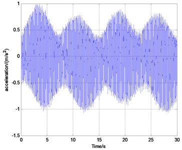
Fig. 3Circumferential vibration characteristic curve vibration acceleration (300 rpm)
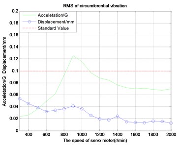
Take a circumferential vibration of the tested product as an example, the vibration performance of the harmonic drive is evaluated by using a vibration characteristic curve shown in Fig. 3. The vibration characteristic curve describes the relationship between the effective value of the vibration acceleration/displacement and the speed of the harmonic drive, which directly reflects the vibration dynamic characteristics of the harmonic drive. The effective value of vibration acceleration is estimated by the test data in time-domain. The effective value of vibration displacement is obtained by calculating the vibration acceleration after filtering and integrating.
Refer to the vibration indicators of high-quality robot joints, the vibration acceleration and displacement value should be less than 0.1g and 0.1mm respectively at the motor speed of 300-2000 rpm. As shown in Fig. 3, there is a peak at the motor speed of 900 rpm, and the effective value of the torsional vibration acceleration exceeds the standard value 0.1 G, so the torsional vibration is abnormal.
3. Three directional vibration analysis
By setting the threshold line, the vibration characteristics curve of the harmonic drive can be used to judge whether the vibration performance of the harmonic drive is qualified or not. When the vibration value exceeds the threshold value, it is necessary to determine the causes of a convex peak in the vibration characteristic curve.
The axial and radial vibration characteristic curves are shown in Fig. 4 and Fig. 5. It’s found that the axial vibration acceleration value increases rapidly at the speed of 1700 rpm-2000 rpm and exceeds the standard value 0.1 G. The radial vibration values are all smaller than the standard value 0.1 G. Therefore, it is necessary to analyze the circumferential torsional vibration and axial vibration of the harmonic drive in frequency-domain, and determine the cause of the abnormal vibration. For analyzing the vibration of a rotating system, the characteristics frequency of each part of the harmonic drive is given in Table 1.
Fig. 4Axial vibration characteristic curve
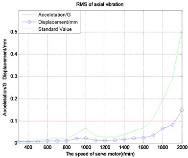
Fig. 5Radial vibration characteristic curve
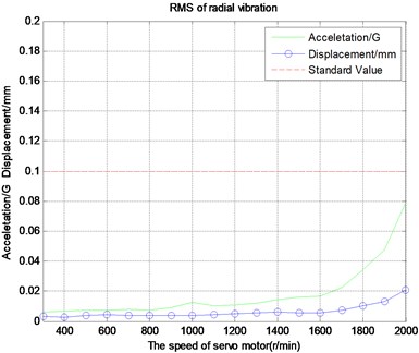
Table 1Characteristic frequency of harmonic drives
Name of characteristic frequency/Hz | Rotation frequency of wave generator | Rotation frequency of flexible spline | Characteristic frequency of rigid spline | Characteristic frequency of flexible spline |
Calculation formula | ||||
Example 300) | 5 Hz | 0.0625 Hz | 10 Hz | 10.125 Hz |
Note: flexible gear number 160, rigid gear number 162, rigid spline fixed. | ||||
3.1. Circumferential vibration
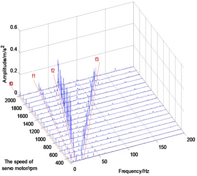
In order to analyze the dynamic relationship between the torsional vibration amplitude, frequency and speed of the harmonic drive, the circumferential vibration waterfall diagram is given in Fig. 6. The circumferential low-frequency vibration consisted of an output frequency of f0, a wave generator rotation frequency f1, a circular spline characteristic frequency f2, and a quadruple frequency f3 of wave-generator. The circular spline characteristic frequency f2 is a main frequency in the circumferential vibration waterfall. The first order natural frequency of the system is 30 Hz, it can be detected by testing the shock response. The reason why the biggest vibration amplitude of the f2 occurred at the speed of 900 rpm is that the circular spline characteristic frequency excited the resonance of the system. Therefore, the main effect of the abnormal torsional vibration is the circular spline error.
Fig. 6Circumferential vibration waterfall
3.2. Axial vibration
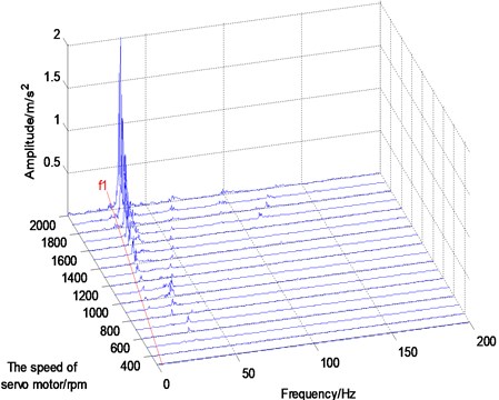
Fig. 7 shows the axial vibration acceleration waterfall. It’s found that the main vibration frequency of the axial vibration is the rotation frequency of the wave generator f1. When the input speed is 1800-2000 rpm, the axial vibration increases rapidly and exceeds the vibration standard value, which is consistent with the axial vibration characteristic curve shown in Fig. 4. The cause of this phenomenon is that the vibration characteristic frequency of the wave-generator in the speed of 1800-2000 rpm is near to the first order axial natural frequency 30 Hz of the harmonic drive. The resonant frequency 30 Hz is obtained by the shock response test. Therefore, the vibration caused by the wave generator is identified as the cause of the abnormal axial vibration.
Fig. 7Axial vibration waterfall
3.3. Radial vibration
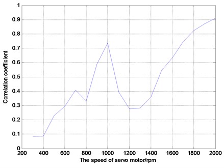
The waterfall diagram of radial vibration acceleration is given in Fig.8, the main vibration consists of a frequency f1 of the flexible spline and a frequency f0 of the wave generator. When the input speed is 1800-2000 rpm, the amplitude of the vibration frequency f1 grows with the increase of the speed, which is consistent with the dynamic response of the radial vibration characteristic curve shown in Fig. 5. The results of correlation analysis show the correlation between the axial vibration and the radial vibration in Fig. 9. The correlation coefficient continuously increased to 0.91 at the speed of 1400-2000 rpm, which indicated that there is a strong correlation between them. Therefore, the radial vibration of the harmonic drive is considered to be affected by axial vibration. When the speed was less than 1400 rpm, the frequency f0 of the flexible spline is the main radial vibration. By comparing the results of the three-directional vibration waterfall, it is found that the vibration frequency of the flexible spline only affects the radial and circumferential torsional vibration.
Fig. 8Radial vibration waterfall
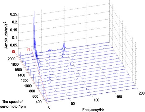
Fig. 9Correlation coefficient between radial vibration and axial vibration
4. Conclusions
Based on the test and research of three-axis vibration of the harmonic drive, the vibration characteristic curve was estimated to assess the vibration performance of a harmonic drive. The vibration of the wave-generator, flexible and circular spline produced different effects on three-axis vibration of harmonic drives. In this case, the vibration of wave-generator was the main factor leading to abnormal axial vibration, the vibration of the circular spline is the main factor leading to abnormal torsional vibration, the vibration of the flexible spline only affects the radial and circumferential torsion vibration. Therefore, the research content of this paper can effectively monitor the vibration performance of harmonic drives, determine the cause of abnormal vibration, and locate the weak link affecting the quality of products.
References
-
Volkov S. I. Harmonic Gear Drive. Publishing House of Electronics Industry, Beijing, 1985, p. 114-120.
-
Wang Xue Jun, Tao Xue Heng Study on torsional vibration characteristics for harmonic drive. Journal of Dalian Institute of Light Industry, Vol. 4, 1996, p. 25-29.
-
Xin Hong Bin, Zhao Fu, Qin Yu Hui Nonlinear analysis of harmonic drive torsional vibration. Mechanical Science and Technology for Aerospace Engineering, Vol. 25, Issue 9, 2005, p. 1040-1044.
-
Tao Xue Heng, You Zhu Ping Dynamic characteristics test and analysis of harmonic gear drive system. Journal of Dalian University of Technology, Vol. 14, Issue 5, 1992, p. 550-554.
-
Zhang You Lin Research on dynamic characteristics of rotary drive of industrial robot. Gear Journal, Vol. 12, 1987, p. 37-41.
-
Yoo C., Ig Park, Choi W. Analysis of structural vibration characteristics of harmonic drive. International Conference on Ubiquitous Robots and Ambient Intelligence, 2014, p. 480-483.
-
Park I. G., Kim I. K., Kim M. G. Vibrational characteristics of developed harmonic reduction gear and fault diagnosis by campbell diagram. International Conference on Control, 2015, p. 2062-2065.
-
Hongbo W. Vibration suppression in a harmonic drive system. Society of Instrument and Control Engineers of Japan, 2015, p. 1037-1041.
About this article

The authors would like to acknowledge the support of National High Technology Research and Development Program of China (Grant No. 2015AA043003).
