Abstract
The paper presents results of measuring the force of the adjustment of the rail switch drive by spindle. The actuation force is the maximum force with which setting valve of the drive done to change position of the point. The simulation research requires proper mathematical model of the actuation force of the rail switch drive. Thus, the verification of such model requires real data measured on real object. The paper presents results of measurement and method of real data analysis.
1. Introduction
The adjusting force is the name of the switches force of switch drive. It is estimated as the maximum value occurred when the clutch is overloaded. The force setting is an important parameter related to the safety train traffic control. Therefore, the measurement of the setting force is very important. Two methods for measuring force adjustment are known and used: the method of measuring the force of the adjustment of the rail switch drive by spindle and the method based on the measuring the setting current voltage. The first method is based on the procedure as follow, placement of the measuring spindle instead of the spindle at the point of connection of the adjusting rod with the slider and measurement directly the force between. The second method is indirect and it based on the measuring the current voltage that flows during the changeover of the switching drive. With the well know current-force relation it allows to determine the value of the adjusting force [1-5].
2. Rail switch drive adjustment force measurement method
The direct method of adjustment force measurement is a technically complicated procedure. This procedure requires a lot of preparatory work. Also, it requires the special agreement from the supervisor of the train traffic control at the station and the switch drive needs to be switch off. These cause the complications to the traffic control procedure at the station. In addition, it is forbidden (in the case of many types of spindles) to operate on the direction of the switch in which the measuring spindle is currently mounted. The next step after obtaining the consent of the measurement procedure is a mechanical disconnect switch drive from the crossover. This is a time-consuming activity, especially in winter conditions. It consists in removing the splines securing the spindle and detaching it from the system. After this step, the measuring spindle must be fitted. In the case of EZK (electrical train) type spindles, it is not advisable to change the electrical connections, so must by hand over the crank handle to the extreme position. For other types of pins – electrically adjust the crossover is possible. According to recommendations [6-10] the crossover needs to be turned three times and then measurement of the setting force can be done. It is important to place the measuring spindle correctly in the opening of the adjusting slider and the adjusting spindle and reset it after several resetting. Correct positioning of the spindle is shown in Fig. 1 [9]. Sometimes the measuring spindle is not properly integrated in the measuring system. The manufacturer of the PAMAR-MS recommends the use of special spacers, but sometimes it is difficult to determine whether the spindle is correctly positioned.
Fig. 1Correct positioning of the spindle during measurement of the adjusting force by spindle
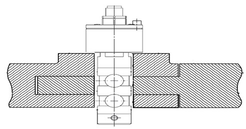
Fig. 2Force measuring system (description in text)
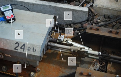
The adjustment force measuring system consists of the essential elements such as (Fig. 2): 1 – measuring spindle, 2 – adjusting slider, 3 – adjusting rod, 4 – switching gear, 6 – measuring electronics. In addition, the needle pin (4) and the control rods (5) can also be distinguished.
The average measuring time is around 10-20 minutes. According the regulations the measurements of adjusting forces should be provide every 2 months in the drives installed in the main tracks and every 4 months in the drives built up in the side tracks. Due to the number of the electric switches used in Poland, which is more than 60000, the problem become much more important. Thus, the experiments on novel methods are needed.
3. Results of measurements
The experiments were conducted with the measurement of the actuation force of the rail switch drive measured by spindle. The sampling time was set as 0,00333 [s] for the 10 seconds recording unit. Some of the results have been depicted in Fig. 3.
The simulation research requires proper mathematical model of the actuation force of the rail switch drive. Thus, based on real data result the approximation functions were determined. Due to the analysis of actuation force distribution (Fig. 3) it can be easily recognized the moment of sliding the clutch, as the period of maximum values. For the better adjustment of the approximation function the data collected during the switching on, 0,15 [s] period before reached maximum values, were analyzed separately with polynomial function. The same procedure was conducted for the data collected during the switching of, 0,666 [s] time period. Such an approach is due to initial guidelines. It allows to generate polynomial functions with 3 degrees (switch on) and 5 degrees (switch off) for the better adjustment of the approximation function. Figs. 4 and 5 present results of measurement and proposition of approximation functions.
Fig. 3Actuation force real data collection
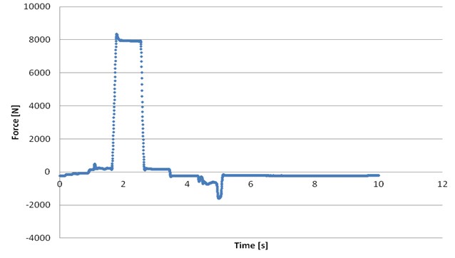
Fig. 4Switch on approximation function
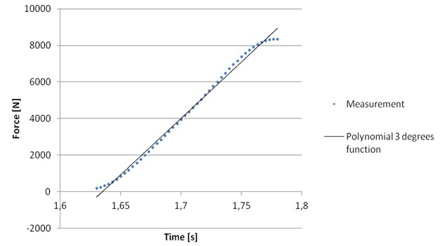
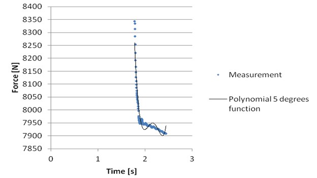
Fig. 5Switch off approximation function
Approximation function presented in Fig. 4 is intensely increasing to the sliding the clutch point. The equation of the approximation function is as follow: with the coefficient of determination 0,9945.
Switch off approximation function is intensely decreasing from the sliding the clutch point and slowly decreasing or remains near to the same value to the end. The equation of the approximation function is as follow: with the coefficient of determination 0,9222.
4. Conclusions
The paper presents results of measuring the force of the adjustment of the rail switch drive by spindle. The results presented were collected as real data collection due to research on the real object. The presented analysis method allows to determine complex approximation function of the actuation force with the proper adjustment even for the chaotic switch on and off periods. Thus, such function can be used as the mathematical model for the simulation research.
References
-
Balcerowicz-Szkutnik M., Sojka E., Szkutnik W. Statistical Inference in Examples and Tasks. University of Economics, Katowice, 2016.
-
Burdzik R. Monitoring System of Vibration Propagation in Vehicles and Method of Analysing Vibration Modes. TST 2012, CCIS 329, Springer, Heidelberg, 2012, p. 406-413.
-
Dąbrowa-Bajon M. Basics of Railway Traffic Control. Politechnika, Warszawska, 2002.
-
Technical Guidelines for the Construction of Rail Traffic Control Devices Ie-4 (WTBE10), PLK S.A., Warszawa, 2014.
-
Michalski R., Wierzbicki S. An analysis of degradation of vehicles in operation. Maintenance and Reliability, Vol. 1, Issue 3, 2008, p. 30-32.
-
Pełka A. Diagnosis of Railway Traffic Control Devices on the Example of a Rail Switch Drive. Doctoral Dissertation, AGH, Kraków, 2009.
-
Operating and Technical Documentation nr DTR-2006/EBISwitch 700, Bombardier, Katowice, 2006.
-
Operating and Technical Documentation nr. DTR-89/EEA-4, Adtranz Zwus Sp. z o.o.
-
Operating and Technical Documentation nr. DTR-99/EEA-5, Bombardier.
-
Mikroprocesorowy miernik siły MMS-1, Operating and Technical Documentation, Kombud, Radom 2001.
-
Operating and Technical Documentation, Measuring instrument. PAMAR-MS, PAMAR-MS/DTR/001, Pamar, Jastrzębie Zdrój, 2017.
About this article

