Abstract
Rubber torsional dampers with one degree of freedom are a long-time proven tool for vibration damping in crank mechanisms, especially for passenger cars. Their advantages include, in particular, a relatively simple design and low production costs. The viscoelastic coupling of the damper ring with the basic dynamic system is realized by a rubber spring made of natural or synthetic rubber. The disadvantages of rubber dampers are, in particular, insufficient damping properties of the rubber spring compared with the optimal values resulting from the respective calculation models. This limits the application of rubber dampers to larger power units, such as diesel engines for tractors and trucks. The article deals with the design and optimization of the parameters of an unconventional rubber torsional damper with two degrees of freedom, which even with limited damping parameters of the rubber springs shows a significantly higher damping effect compared to the common design of rubber dampers with one degree of freedom.
1. Introduction
A typical design of rubber torsional dampers [1-3] is illustrated in Fig. 1(a). The connection of the relatively thin rubber layer to the metal parts is made using vulcanization.
Fig. 1a) Vulcanized rubber torsional damper, b) rubber torsional damper, in which the elastomer ring is assembled between two metal components [4]
![a) Vulcanized rubber torsional damper, b) rubber torsional damper, in which the elastomer ring is assembled between two metal components [4]](https://static-01.extrica.com/articles/19042/19042-img1.jpg)
a)
![a) Vulcanized rubber torsional damper, b) rubber torsional damper, in which the elastomer ring is assembled between two metal components [4]](https://static-01.extrica.com/articles/19042/19042-img2.jpg)
b)
For some smaller engines of passenger cars, a different technology is used instead of vulcanization (see Fig. 1(b)). The rubber element is pressed by the pulsating force into the free space between the damper ring and the pulley using the sliding media. The axial displacements of the rubber spring during the engine running are avoided by a suitable design of the free space.
For internal combustion engines with higher power output, the design of rubber torsional dampers is more difficult because the dissipated power in the rubber elements can reach up to hundreds of watts, and insufficient heat removal would cause them to be quickly destroyed.
By attaching the rubber damper to the crank mechanism, the number of degrees of freedom of its torsional system will be increased by 1. This means that the first two frequencies are now to be taken into consideration when computing torsional vibrations.
2. Optimization of a torsional vibration damper with one degree of freedom
The characteristic features of a single dynamic vibration damper with viscoelastic coupling by a two-parameter parallel rheological model (the so-called Kelvin model) are known from the literature [1, 2]. A basic system with one degree of freedom, harmoniously excited, is usually considered. Fig. 2 shows a schematic of the vibration damper and its defined non-dimensional parameters: relative damper size , damper tuning , damping ratio , ratio of excitation and natural frequency , torque magnification factor in basic system , torque magnification factor in damper system , static amplitude of the basic system and relative amplitude magnification factor in damper system. The known optimization strategy uses the so-called fixed points of amplitude characteristics [5]. For optimal tuning of and damping of corresponding to the relative damper size the maximum torque magnification in basic system is given by .
However, when designing a rubber torsion damper for a crank mechanism, this optimization strategy is only available to a limited extent. The moment of inertia of the damper ring can be designed with the necessary precision, but in the stiffness of the rubber part, a certain range of the values given by the production tolerances, temperature dependence and aging of the rubber must be taken into account. The very uncertain quantity is the damping property of the rubber spring. The damping in rubber is predominantly hysteresis, its size can be very difficult to influence, and is usually several times smaller than the optimum value according to Fig. 2.
Fig. 2The principle of a dynamic damper with a two-parameter parallel rheological model [2, 3]
![The principle of a dynamic damper with a two-parameter parallel rheological model [2, 3]](https://static-01.extrica.com/articles/19042/19042-img3.jpg)
3. Computational model of the crank mechanism torsion system
To calculate the torsional vibrations of the crank mechanism with a rubber damper, the common calculation model according to Fig. 3 may be used.
Since the drive torques in internal combustion engines can be considered periodic, the torsional vibration computation can be performed in the frequency domain, i.e. the harmonic components of determined by Fourier analysis [6] can be considered on the right side of the equations of motion. The complex angular amplitudes of the individual parts of the torsional system are then obtained by solving the system of equations:
The individual elements of the matrix of this system of equations are given by the following relations:
Since the system matrix in Eq. (1) is tridiagonal, it is possible to use the so-called compact scheme, which is a certain modification of the Gauss elimination method. The number of mathematical operations required to compute all complex torsional amplitudes of the system with degrees of freedom according to Fig. 3 is 5(), i.e. it increases only linearly with the number of degrees of freedom, whereas for general Gaussian elimination the number of operations 1/33 is required [7-11].
In this way, a solution can be reached for the required number of harmonic components, and from their harmonic synthesis, periodic angular displacements are obtained.
Fig. 3Torsional dynamic model of a crank mechanism [1-3]
![Torsional dynamic model of a crank mechanism [1-3]](https://static-01.extrica.com/articles/19042/19042-img4.jpg)
4. Computational models of the torsion system with dynamic damper
Computational models of crank mechanism torsion systems with simple dynamic dampers with one degree of freedom can be created simply by using the Eq. (1). A dynamic damper with two degrees of freedom consists of two masses connected in parallel by a viscoelastic coupling to the basic system. To calculate the amplitudes of harmonic vibrations, a system of equations, whose matrix is no longer tridiagonal, will be created, and the advantages of the quick algorithm solution of the Eq. (1) could not be used for subsequent optimization calculations. However, the following procedure can be used to incorporate the dynamic damper with two degrees of freedom into the torsion system computational model, in which case the tridiagonal matrix of the equation system will be retained.
Supposing that a dynamic damper with one degree of freedom with a moment of inertia and with the complex stiffness of its viscoelastic coupling is connected at the point of the basic torsional system. If the basic system oscillates in the point with the amplitude then the torque, at which the damper system affects the basic system, will be a function of the amplitude which is the function of the excitation frequency and of the damper parameters.
The ratio of the torque and the angular acceleration of point:
expresses physically the equivalent moment of inertia of , which is situated at the point.
If is the damper system affected by the oscillation of the basic system with amplitude and the angular frequency , the simple equation shall be valid:
where is the relative amplitude between the damper seismic ring and the point of the basic system where the damper is connected. From Eq. (5), the relative amplitude of the can be expressed as a function of the damper parameters and the amplitude of the point of the basic system in the form:
For the torque of the dynamic damper that acts on the basic system is valid:
and after insertion from Eq. (6) and modification, the following relation follows:
The equivalent moment of inertia at the point, which simulates the effect of the dynamic damper on the basic system, is then given by equation:
By using the equivalent moment of inertia, it is possible to similarly simulate the parallel connection of another damper at the point, while the structure of the mathematical model according to Eq. (1) created for the basic dynamic system of the crank mechanism and the number of degrees of freedom do not need to be changed.
5. Application of a rubber damper with two degrees of freedom
An unconventional rubber damper with two degrees of freedom has been developed and experimentally validated for a six-cylinder inline diesel engine designed for use in tractors, commercial vehicles and also industry.
The version of this engine for heavy tractors has a nominal speed of 2 200 rpm. A rubber damper with one degree of freedom has been designed and optimized for torsional vibration damping, the effect of which in the operating range of the engine speed is shown in Fig. 4.
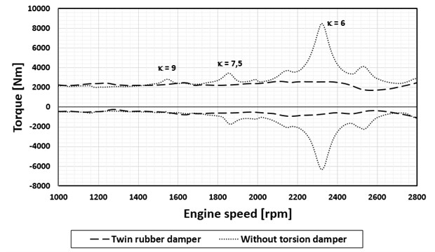
At the same time, however, it is obvious that for a version of the engine with a nominal speed of 2 600 rpm this damper no longer has the necessary damping effect. As a solution to this problem, a rubber damper with two degrees of freedom was designed and optimized.
Due to the fact that the damping properties of a rubber spring cannot be practically much influenced, the minimum hysteresis damping value was considered. As the optimization parameters were considered: the total moment of inertia of the two damping rings and the parameter determining its distribution on both parts and the torsion stiffness of the two rubber components. For the damper parameters determined by this way, the calculations have further verified that any increase in damping properties of the both rubber components over the assumed minimum values will always be positive.
The effect of the rubber torsional damper with two degrees of freedom is shown in Fig. 5.
Fig. 4Maximum torque values at the crank pin by the flywheel, nominal engine speed 2 200 rpm
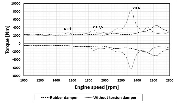
Fig. 5Maximum torque values at the crank pin by the flywheel, nominal engine speed 2 600 rpm
Further development of this diesel engine will also focus on the application of alternative fuels and modern manufacturing technologies [12, 13]. This would affect the driving torques. Preliminary analyses have shown that the designed rubber dampers will have the necessary damping effect for this variant.
6. Conclusions
The application of torsion dampers with one degree of freedom in larger motors is usually not possible as the damping properties of rubber springs are not sufficient. The solution in these cases can be a rubber damper with two degrees of freedom. At optimum torque values of both parts and the torsional stiffness of both springs, a significantly greater damping effect can be achieved over the entire operating range of the engine, even with minimal hysteresis damping values. The advantages of such a solution compared to a simple rubber damper were illustrated on a six-cylinder diesel engine.
References
-
Genta G. Vibration of Structures and Machines. Springer-Verlag, New York, 1993.
-
Nestorides E. J. A Handbook on Torsional Vibration. Cambridge University Press, Cambridge, 1958.
-
Heisler H. Advanced Engine Technology. 1st Edition, Arnold, Oxford, 2002.
-
Torsional Vibration Dampers, 2016, https://www.vibracoustic.com/products/passenger-car/powertrain/torsional-vibration-dampers.
-
Lewis F. M. The extended theory of the viscous vibration damper. Journal of Applied Mechanics, Vol. 22, 1955, p. 515-552.
-
Tůma J. Vehicle Gearbox Noise and Vibration: Measurement, Signal Analysis, Signal Processing and Noise Reduction Measures. John Wiley, Chichester, 2014.
-
Gupta, A. Numerical Methods using MATLAB. Springer-Verlag, New York, 2014.
-
Porteš P., Kučera P., Píštěk V., Fojtášek, J., Zháňal L. Modern tools for vehicle development. Engineering Mechanics, 2017, p. 54-57.
-
Kučera P., Píštěk V., Porteš P. Automatic differential lock control in a truck – straight drive. Engineering Mechanics, 2016, p. 334-337.
-
Prokop A., Řehák K. Virtual prototype application to heavy- duty vehicle gearbox concept. Engineering Mechanics, 2017, p. 810-813.
-
Drápal L., Šopík L., Vopařil J. Investigation of torsional vibration of unconventional crank train. Vibroengineering Procedia, Vol. 7, 2016, p. 31-36.
-
Medeiros H. S., Pilatau A., Nozhenko O. ets. Microwave air plasma applied to naphthalene thermal conversion. Energy Fuels, Vol. 30, Issue 2, 2016, p. 1510-1516.
-
Mogila V., Vasyliev I., Nozhenko E. The use of biofuel on the railway transport. Transport Problems, Vol. 7, Issue 1, 2012, p. 21-26.
About this article

This work is an output of the internal BUT Research Project Reg. No. FSI-S-17-4104.
