Abstract
The purpose of this study is development of micro ultrasonic motor for miniature robot arm. It will be assembled to a miniature robot applied to a mesh robot to represent the shape and stiffness of the surface of objects. In the first stage, the authors have developed a micro motor by ultrasonic technology. It has two components: a stator (a cube of 3 mm size) and a rotor (diameter of 1 mm). The authors have designed a new stator and a rotor to increase output torque. The first trial motor shows successfully the potential of the final goal of 5 μNm and 3 rpm with a reduction gear system.
1. Introduction
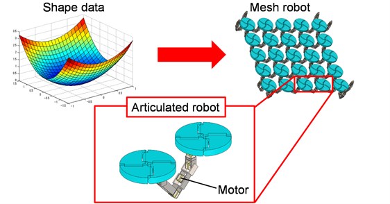
There are special robots and manipulators working in the hazardous environment such as deep sea, outer space or atomic plants. In these applications, master-slave type of robot is widely used; the operators control the robots and obtain the information of handling objects such as contact force, temperature and visionary information from the robot's sensors. This is tele existence technology. The tele existence needs the function of the tactile presentation of the objects such as shape and stiffness and so on. It is important technology because the robots are handling much far away from the operators, but they have to feel the object by themselves to precede a sophisticated task. For these applications, the authors have proposed a new tactile presentation device as shown in Fig. 1. This is a mesh type of robot. It moves each plate to desired direction and position respectively to show the shape of the target objects. It can also show the stiffness and smoothness of the surface by controlling compliance of the mesh robot.
Fig. 1Schematic diagram of mesh robot
In this study, the authors have developed a micro motor adapted for the robots of mesh robot as the first stage. The specification of the motor is as follows:
1) It should be as large as a 3 mm-sized cubic or smaller.
2) It should have the maximum output torque of 5 μNm or more.
3) It should have the maximum rotational speed of 3 rpm or more.
Now that it is difficult that only one motor meets the specification actually, the authors have prepared a small reduction gear system. The authors have also applied ultrasonic technology to develop the motor in order to reduce the size of it [1-6]. This is vibromotor and driven by ultrasonic vibration.
2. Newly designed stator and rotor
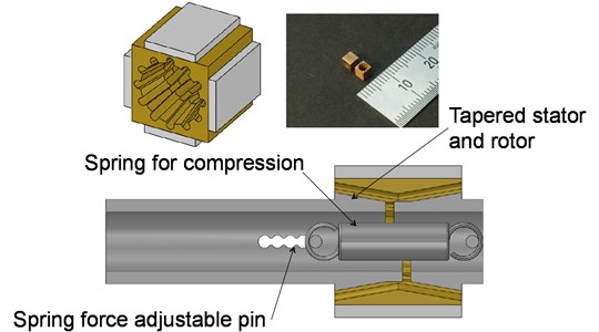
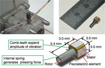
A new motor consists of a stator and a rotor. The rotor is made of phosphor bronze with a through hole in the center (Fig. 2). The hole of the stator is tapered to obtain wedge effect. It contributes contact force control between the stator and the rotor to increase and make adjustment easily. The contact force can be controlled by a spring in it. Adding that, the surface of hole has teeth; it also contributes to driving the rotor firmly at the edge of teeth and the resonant frequency decrease for driving.
Fig. 2Overview of a new motor
In the design stage, the authors have made FEM analysis of the vibration of the stator with and without teeth. The authors have assumed to adopt three-wave vibration mode. Suppose that one wave correspond four teeth, the hole should have twelve teeth. Ideally it should have sixteen teeth or more to transmit the force firmly, but the production process in a small hole is limited.
Fig. 3 shows vibration modes by FEM analysis. Three elastic waves are traveling along the surface. Both vibration modes are expected to drive the rotor effectively. However, the resonant frequency with teeth model is much lower than that of the model without teeth. Generally speaking, lower resonant frequency has advantage for controlling it due to wider frequency range.
Fig. 3Vibration mode of rotation
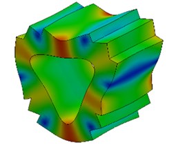
a) Without teeth
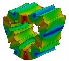
b) With teeth
Next, the authors have made each our stators with and without teeth and measured resonant frequencies. The results are also shown in Fig. 4 and Table 1. It shows that each stator’s resonant frequency meets good coincidence with that of analysis results and the errors among each stato’s frequencies are small because the production process of the stators is controlled carefully.
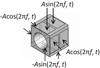
Finally, piezoelectric ceramics are laminated on the side faces of each stator. Alternative voltage is applied to each ceramic with phase difference as shown in Fig. 5.
Table 1Resonance frequency
Eigenvalue analysis | Without teeth | With teeth |
353.5 kHz | 245.5 kHz | |
ch 1 | 345.8 kHz | 248.3 kHz |
ch 2 | 345.6 kHz | 248.3 kHz |
ch 3 | 345.8 kHz | 248.0 kHz |
ch 4 | 345.6 kHz | 248.2 kHz |
Fig. 4Measurement of impedance
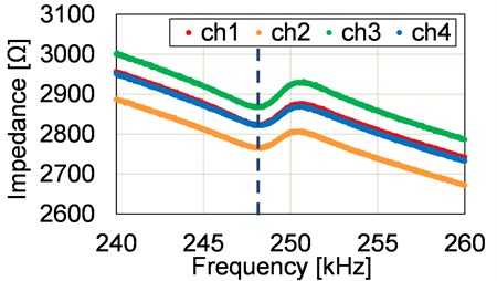
Fig. 5Applied voltage
3. Characteristics of the motor
The authors have made experiments of characteristics of the motor. The experimental apparatus is shown in Fig. 6-7. The motor is supported with acrylic plate so as to avoid suppressing driving vibration of the motor. A small magnetic device measures the rotational speed and position.
Fig. 6Experimental apparatus
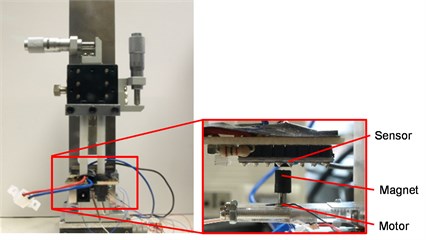
Fig. 7The new motor
Firstly, the authors have evaluated the resonant frequency characteristics. The results are shown in Fig. 8 and Table 2. The stator with teeth has wider frequency control range. It is the advantage of the control because the controllable range of the ultrasonic motor with higher resonant frequency is generally narrow and it causes poor controllability.
Secondly, the authors have evaluated rotational speed by changing phase difference of every ten degree. The results are shown in Fig. 9. The stator without teeth shows dead zone at phase difference zero, however the stator with teeth shows the smooth sinusoidal curve without dead zone (the error speed at phase zero is caused by offset in a driving circuit or miss alignment of the ceramics and it is adjustable easily).
Thirdly, the authors have estimated the rotational speed changing applied voltage. The results are shown in Fig. 10. The stator with teeth shows higher speed at the same applied voltage. Based on the above discussion and experiments, the authors have concluded to adopt the stator with teeth.
Finally, the authors have made experiment of output torque by using simple pulley and weight method. The results show that maximum output torque is 12 μNm, and maximum rotational speed is 2000 rpm. Now that the authors have prepared the reduction gear system with sixty-eight gear ratio, the output torque of the gear is about 0.8 μNm and rotational speed is about 30 rpm. The specification of it is 5 μNm and 3 rpm. Therefore, the output toque of the motor should be more than 70 μNm but rotational speed can be around 200 rpm.
Fig. 8Characteristics of resonant frequency
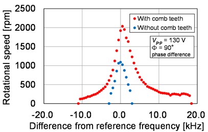
Fig. 9Rotational speed versus phase difference
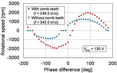
Fig. 10Rotational speed versus applied voltage
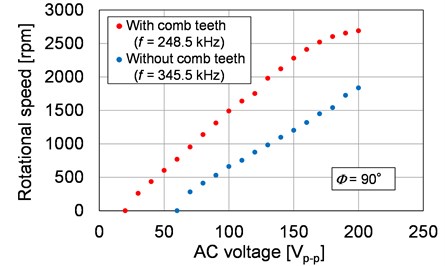
Table 2Characteristics of resonant frequency
Without teeth | With teeth | |
Reference frequency | 345.5 kHz | 248.0 kHz |
Frequency at maximum speed | 345.5 kHz | 248.5 kHz |
In the next stage, by exchanging the spring with higher stiffness to make pushing force increase, the goal output torque will be obtained.
4. Conclusions
The authors have concluded as follows.
1) The authors have made a new design of stator and rotor of micro ultrasonic motor and manufacture it to elucidate the characteristics of it.
2) The authors have demonstrated that the stator with teeth has better characteristics of rotational speed and resonant frequency.
3) The first trial motor showed the possibility of the goal of 5 μNm and 3 rpm with a reduction gear system successfully.
References
-
Chen S., Mulgrew B., Grant P. M. A clustering technique for digital communications channel equalization using radial basis function networks. IEEE Transactions on Neural Networks, Vol. 4, Issue 4, 1993, p. 570-590.
-
Sashida T., Kenjo T. An Introduction to Ultrasonic Motors. Oxford University Press, Oxford, 1993.
-
Ferreira A., Minottia P. High-performance load-adaptive speed control for ultrasonic motors. Control Engineering Practice, Vol. 6, Issue 1, 1998, p. 1-13.
-
Hoshina M., Mashimo T., Fukaya N., Matsubara O., Toyama S. Spherical ultrasonic motor drive system for pipe inspection. Advanced Robotics, Vol. 27, Issue 3, 2013, p. 199-209.
-
Takesue N., Ohara T., Ishibashi R., Toyama S., Hoshina M., Hirai Y., Fukaya N., Arata J., Fujimoto H. Position control methods of spherical ultrasonic motor. Proceedings of IEEE/RSJ International Conference on Intelligent Robots and Systems, 2010, p. 3061-3066.
-
Moriya T., Furukawa Y., Akano Y., Nakajima A. Experimental Study on a Miniature Ultrasonic Motor Using a Coiled Stator. IECEI Technical Report, No. US2005-29, 2005, p. 41-45, (in Japanese).
About this article

This work was supported by Acquisition, Technology and Logistics Agency of Japan.
