Abstract
Regenerative chatter is major issue in turning operations, which lowers the machining efficiency and parts quality. It is usually caused by the intense self-excited vibration between the cutting tool and the work piece. In this paper, we intend to visualize the tool-work system vibration during the three degrees of freedom cylindrical turning on CA6140 lathe machine. This was achieved by building up a dynamical model for the process with taking into consideration the dynamical properties of the cutting tool. Thus, the theoretical analysis of the natural frequencies, vibration mode and transient response on tool-work system vibration during this process was simulated using Matlab/Simulink. The results showed a variation in the first-order natural frequency vibration of the cutting tool. However, during the transit stage, vibration was gradually decreased and became stable. Finally, the proposed model was verified, and the results were found to be consistent with previous research work. This model provides new technique in evaluation and understanding the cutting tool vibration of three degrees of freedom cylindrical turning.
1. Introduction
As science and technology develops, researchers start paying attention to the precision and efficiency of the machinery. In the case of machining processes, this mean to satisfy the requirements for high performance process as well as obtaining good quality machined parts. During lathe turning, the vibration would inevitably occur and affect the process accuracy and efficiency [1, 2]. This is generally caused by the intense self-excited vibration between the cutter and the workpiece, which is often called chatter. In other words, chatter has been the main obstacle in improving the capability of lathe machine for producing high quality products. Hence, studying and analyzing flutter during turning process is very important [3, 4].
Since 1906, researches have studied turning flutter mechanism, and thus, have come up with different theories regarding this phenomenon. More generally accepted theories include regenerative theory, mode shape coupling mechanism, negative friction and the principle of cutting force hysteresis. Among all these, the regenerative chatter theory is the most widely accepted and applied. It undertakes systematic analysis and demonstration of the process from the point of view of exciting force and amplitude. Therefore, it can reasonably explain the turning flutter under the single degree of freedom (SDOF) [5, 6]. However, the SDOF is only effective on the turning flutter of certain buckling modes because it has some shortcomings that have not been addressed. The major issue is hard to determine the main flutter direction of the cutter, because SDOF is not suitable to explain flutter of non-free turning operation. Hence, SDOF is not appropriate to be applied for solving actual turning flutter control [7].
This paper based on the previous studies and focuses on the regenerative chatter of external lathe work cutter-workpiece system of the CA6140 lathe. Considering the dynamic characteristics of the tool, this study is associated with building up a kinetic model for Cylindrical Turning Flutter of 3-DOF model. The theoretical analyses implemented is this study, include the frequency and the principal mode of the model. Furthermore, it undertakes a simulation study by the means of the transient vibration response of the cutter (at the time the tool touches the workpiece until stable machining is established) using Matlab/Simulink.
2. Materials and methods
The regenerative chatter during Cylindrical Turning Processing is complicated. There is no model that could completely simulate the actual situation without any deviations. The kinetic model developed in this paper defines the practical problem and proposed the solution. However, it is a hypothetical model of simplified key elements, as well as the input and the output elements.
2.1. Analysis of the turning process chatter
Before building up a kinetic model for Cylindrical Turning, we should analyze the active body chatter during the process. The workpiece-cutter system with regenerative chatter should have two requirements. Firstly, a disturbed system generates dynamic cutting force. Secondly, the system has to gain energy to maintain the chatter, thus, the replenished energy is of the dynamic cutting force [8]. When the cutter-workpiece system in the state of regenerative chatter the processing conditions, and dynamic characteristics of cutter and workpiece determine its occurrence. In other words, under certain machining conditions, the inherent frequency, dynamic cutting force and dynamic stiffness define the active body vibration. Therefore, during the actual lathe operation, the analysis of the active vibration body depends on the above mentioned parameters [9, 10].
2.2. Three-degrees of freedom dynamic model
In order to simplify the analysis, it has been assumed that the turned cylindrical workpiece is a rigid body and the cutter is considered as the active body vibration. The cyclical change of the dynamic cutting force caused by the cutter-workpiece system generates chatter at axial, radial and tangential directions. According to the equivalence, simplicity and successive approximation of the kinetic model, the cutter could be seen from the perspective of three degrees of freedom elastically guided and damped system. Therefore, it can be simplified in the three axials, radial and tangential directions as shown in Fig. 1. Where () is the feed force, () is the back force, () is the main cutting force and () is the resultant force acting on the cutting tool.
Fig. 1Dynamic model of the oblique cylindrical turning
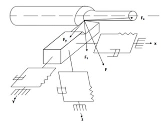
Fig. 2Inertia model of the oblique cylindrical turning
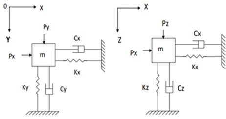
For easy determination of the kinetic model of this process, the tool-workpiece system in Fig. 1 is replaced by the inertia element Fig. 2. This describes the regenerative chatter mechanism of the process under three-degree of freedom. Where the three-dimensional model of the tool-workpiece system is represented by two plane coordinate systems. However, the mechanical model still has three degrees of freedom, where the inertia element is the mass , the elastic elements are , and , and the damping elements are , and .
3. Results and discussion
3.1. Formulation of the dynamic model
The actual turning process of the cylindrical workpiece is proposed to be oblique cutting as illustrated in Fig. 3. At each revolution of the workpiece, the cutting tool moves from position I to position II and removes layers from the workpiece in the form of chip [11]. Where the removed layer cross-section area in the datum is called the cutting area, and is denoted by the shaded region Fig. 3. Moreover, during cutting action, the cutting tool is subjected to a resultant cutting force () that has three perpendicular components. This helps in the formulation of the three-degree of freedom dynamic model that will help in the development of the required regression model for solving the problem.
Fig. 3Schematic diagram of oblique cylindrical turning
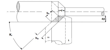
Therefore, the cutting area can be calculated as follows:
where: is the cutting area, is uncut chip thickness, is an uncut chip width:
where: is major cutting edge angle; is the total cutting thickness of the () tool along the radial direction of the workpiece cutting thickness.
According to the empirical formula of cutting force, resultant cutting force () can be expressed as follows:
where is cutting coefficient, which depends on the material and size of the workpiece, cutting tool material and geometry, chip thickness and cutting speed [12]. In this paper, the selected tool geometry as recommended by the supplier is tabulated in Table 1.
Table 1Geometric angle of the cutter
Major cutting edge angle / () | Minor cutting edge angle / () | Rake angle / () | Angle of inclination / () |
45 | 10 | 15 | 0 |
Combining Eqs. (1), (3) into Eq. (4) to give the resultant cutting force acting on the tool. Thus, Eq. (4) can be expressed as follows:
The cutting force is resolved into three mutually perpendicular components; axial or feed force (), thurst force (), and main cutting force () respectively. According to actual machining test: 45°, 15°, 0.
The following are the approximated relationship between resultant force and its three components:
where: , and are the excitation cutting forces in the , and direction respectively. Hence, by substituting Eq. (5) into Eq. (6) the cutting force components can be expressed as follows:
3.2. Mathematical model
The regression model development was achieved by using the kinetic model of the system Eq. (7) and the principle of Newton’s second law. Accordingly, the equations of motion for the vibrated system were expressed as follows:
where , , are the masses, and , , are the damping coefficients and , , are the structure stiffness of the machine tool in the three respective directions. By making use of Eqs. (7) and (8), we can obtain the complete mathematical model of the three-degree of freedom vibrated system. Thus, the model is expressed by the following matrix:
The value of (0) which is the average cutting depth can be found form the equation motion where 52 rad/s, 0.005 m, 0.003 m.
The numerical solution for the Mathematical model can be obtained by substituting the parameters of Table 2 into Eq. (9).
3.2.1. The natural frequency of vibrated system
The next step in this analysis is to solve the system of differential equations for the vibrated motion. This enables the determination of the system frequency for un-damped n-degree of freedom vibration. In this case the general matrix equation is given as follows:
where is the mass matrix, is the stiffness matrix, is the generalized coordinate vector. It is assumed that the system is under harmonic vibration. Therefore, the general equation of motion can be put as follows:
where is arbitrary constant, is the natural frequency of harmonic vibration and is the initial phase angle.
Table 2Input parameters
No | Parameter | Values | Unit |
1. | Mass () | 0.0235 | kg |
2. | Tool elastic modulus () | 2.10×10¹¹ | N.m-2 |
3. | Tool-sectional area () | 0.0001 | m2 |
4. | lengthening of the tool () | 0.0900 | m |
5. | Total length of the tool () | 0.0400 | m |
6. | cutting coefficient () | 2.50×10⁹ | N.m-2 |
7. | Depth of the cutting tool at Each time () | 0.0030 | m |
8. | Damping ratio direction () | 0.0285 | N.s-1.m-1 |
9. | Damping ratio direction () | 0.0157 | N.s-1.m-1 |
10. | Damping ratio direction () | 0.0285 | N.s-1.m-1 |
11. | Feed rate () | 0.0003 | m.r-1 |
By substituting Eq. (11) in Eq. (10) we can get the following expression:
In order to generate a solution for , make its coefficient determinant equal to zero:
Eq. (13), is called the natural frequency equation or characteristic equation which satisfy the conditions of the natural frequency . After the determinant of the characteristic equation is expanded, an (th) order polynomial of is obtained. For the positive definite system, we need to obtain the positive real roots where 1, 2,..., and () is called natural frequencies of the system. In most cases, the natural frequencies are not equal and can be arranged from small to large, in ascending order;
By making use of the input parameters of Table 2 in Eq. (13) and the MATLAB Software, the natural frequencies of the system were calculated and listed below. 2731 (Hz), 3233 (Hz), 17083 (Hz).
3.2.2. The main modes of the vibrated system
Information about the main modes of the vibrated system can be determined by substituting the calculated natural frequencies values into the deferential Eq. (12). This enables the determination of the resultant modal vector u of the system which is expressed as follows:
The main modes of the matrix:
According to the above result, the main mode of the vibrated system was represented by Fig. 4. It obvious that the chatter due variation for the three natural frequencies takes place at three directions (axial, radial and tangential) on the cutting tool. However, the chatter of the cutter is the large in and directions, while it is minimum at -direction. The result was found to be consistent with all three natural frequencies. This is mainly due to the fact that the cutting tool is more rigid in direction than in and directions. The relative vibration of the system in the direction of the respective degrees of freedom can be obtained by the vibration pattern. The graph also shows that the vibration in the direction is the largest at the first order natural frequency.
3.3. Transient response of the cutter
According to the developed model of the three degree of freedom cylindrical turning, it is obvious that chatter in the specified three directions is zero at the initial contact between the cutting tool and workpiece. Then it increases with the progression of the cutting action, and become stable at the transient stage. Therefore, it is desirable in this section and following subsections to drive the mathematical expression for the chatter amplitude and speed, and the system state equation. The application of the three degrees of freedom dynamic model with the aid of MATLAB simulation can assist in the determination of transient response of the cutting tool. Based on Eq. (9), It was assumed that at the initial contact between the cutting tool and workpiece, the amplitude and speed at all directions is zero. This is regarded as the initial condition for the Differential equation of system motion. Therefore, the differential equation of motion become as follows:
In general, the answer to the kinematic equation of system vibration can be solved through differential equation of system movement. Where the numerical solution of differential equations is often transformed into a state space equation of a standard format [13].
In this case, we represent the system space variables by Eq. (15). Then the kinematic equation of the vibrated system can be transformed into a state space equation, as shown in Eq. (16).
where: ; ; ; ; .
Then the initial conditions for this state of space equation can became as follows:
To analyze the vibration amplitude of the vibrated system at the maximum excitation frequency, it is necessary to analyze the steady-state output value of the vibrated system at different excitation frequencies during the cutting process. Therefore, the phase angle difference is considered large, and the theoretical data is provided for the actual production situation. Using Matlab through the complex domain frequency response function, we can obtain the amplitude-frequency curve and the phase–frequency curve of the vibrated system as shown in Fig. 5.
According to the characteristic analysis of the frequency response of the regenerative chatter of the turning process, the vibration frequency of the system is found to be 2800 rad/s (Fig. 5). The vibration amplitude and phase difference at the three vibration directions are the largest with excitation frequency of 445.9 Hz. The spindle speed is also maximum to avoid the frequency range in the workpiece, resulting in lathe regeneration flutter vibration.
Fig. 4Vibration mode of the system
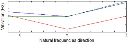
Fig. 5Characteristic curves of the vibrated system
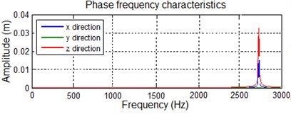
a)
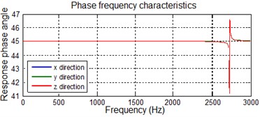
b)
3.4. Matlab/Simulink simulation
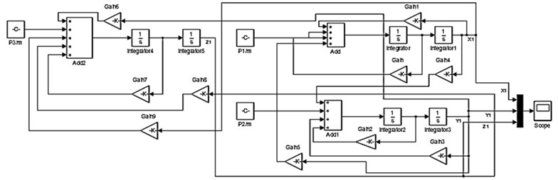
Fig. 6 shows the block diagram for converting the state space equation of the system vibration to numerical simulation, using Matlab/Simulink [14].
Fig. 6Matlab/Simulink simulation block diagram
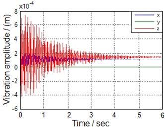
By employing the Matlab/Simulink, the turning process in question was simulated in the time from the initial contact between the cutting tool and workpiece until the cutting process become stable. Fig. 7(a) shows the direction of vibration of the cutting tool. It can be seen that when the cutter touches the workpiece, the chatter at all directions is high. This attributed to the sudden change in the dynamic cutting force. As the time passes by, the chatter starts getting stable to a certain point. When the whole system gets stable, the chatter at direction and directions chatter is high.
However, the chatter at -direction is comparably small and almost negligible. This result is consistent with previous studies findings. Therefore, this proves that the kinematic model of the three degrees of freedom can adequately describes the cylindrical turning process in question. Moreover, the first natural frequency and second natural frequency of the vibration system are 2731 Hz and 3233 Hz, which seems to be close to each other. Therefore, the transient response of the vibration system will occur “” situation as shown in Fig. 5(b).
Fig. 7Transient response of the vibrated system
a)
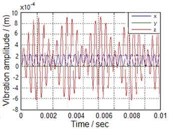
b)
4. Conclusions
Considering the dynamic characteristics of the cutter in cylindrical turning processing, these three degrees of freedom dynamic model of regenerative chatter is rational and representative. Under the first natural frequency, the chatter at the direction is the biggest and followed by that in direction. The -direction is minimum chatter. When the cutter touches the workpiece, the chatter from all the directions are very dramatic. As cutting action progress, the chatter stabilizes to a certain point. The turning process gets stable, at the transient cutting stage, however, chatter in the and direction is high, and in direction remained minimum. This result is consistent with previous research work. The model is verified by applying it to a concrete turning operation. Finally, this study proved that a three-degree of freedom model of chatter could very well visualize the turning process in a simple and reliable way.
References
-
Cardi A. A., Firpi H. A., Bement M. T., Liang S. Y. Workpiece dynamic analysis and prediction during chatter of turning process. Mechanical Systems and Signal Processing, Vol. 22, Issue 6, 2008, p. 1481-1494.
-
Cardi A. A. On the Development of a Dynamic Cutting Force Model with Application to Regenerative Chatter in Turning. Georgia Institute of Technology, 2009.
-
Han X., Ouyang H., Wang M., Hassan N., Mao Y. Self-excited vibration of workpieces in a turning process. Proceedings of the Institution of Mechanical Engineers, Part C, Journal of Mechanical Engineering Science, Vol. 226, Issue 8, 1958, p. 1970-2012.
-
Zhang Y., He Y., Chen X. Simulation analysis on the cylindrical turning based on MATLAB/Simulink. Mechanical Research and Application, Vol. 2, 2013, p. 11.
-
Kashyzadeh K. R., Ghorabi M. J. O. Study of chatter analysis in turning tool and control methods – a review. International Journal of Emerging Technology and Advanced Engineering, Vol. 2, Issue 4, 2012, p. 1-5.
-
Mandal N. K., Roy T. Advanced Materials Prediction of Chatter Vibration and Stability Mapping in Cylindrical Turning of AISI 1045 Steel. Vol. 5, Issue 1, 2015, p. 43-49.
-
Gavin H. P. Vibrations of Single Degree of Freedom Systems. 2010.
-
Al-Regib E., Ni J., Lee S. H. Programming spindle speed variation for machine tool chatter suppression. International Journal of Machine Tools and Manufacture, Vol. 43, Issue 12, 2003, p. 1229-1240.
-
Siddhpura M., Paurobally R. A review of chatter vibration research in turning. International Journal of Machine Tools and Manufacture, Vol. 61, 2012, p. 27-47.
-
Fu S. G. Foundation of Mechanical Manufacturing Technology. Tsinghua University Press, Beijing Google Scholar, 2004.
-
Pratt J. R. Vibration Control for Chatter Suppression with Application to Boring Bars. Faculty of Virginia Polytechnic Institute, 1997.
-
Purushotham A., Sravan Kumar G. Experimental studies on vibration characteristics of lathe machine\ntool under different cutting conditions. International Journal of Mechanical and Production Engineering Research and Development, Vol. 3, Issue 5, 2013, p. 57-60.
-
Michael R. H. Vibration Simulation using Matlab and Ansys. New York Chapman Hall/CRC, 2001.
-
Saleh K., Sims N. D. The self-excitation damping ratio in variable speed milling. Proceedings of the World Congress on Engineering, Vol. 2012, Issue 3, 2012.
About this article

This paper is funded by the International Exchange Program of Harbin Engineering University for Innovation-oriented Talented Cultivation.
