Abstract
To investigate the relationship between the fractured area created by hydraulic fracturing and various fracturing parameters of underground coal mines, we applied fracture and porous media fluid-solid coupling theory to establish a numerical model of hydraulic fracturing. Three-dimensional numerical simulation of hydraulic fracturing of coal seam in a coalmine was performed using the proposed numerical model. We examined the relations between the fractured area and the injection volume, injection rate, and viscosity of the fracturing fluid. The results showed that the fractured area increased with increasing injection rate, however, the extension rate slowed down; the fractured area initially increased then decreased with increasing viscosity; the fractured area increases rapidly with the increase of the water injection volume at the beginning, then begin to slow, eventually approximate linear growth.
1. Introduction
Highly efficient extraction of coalbed methane is of great importance to the safety of coalmine production and for the development of the state energy strategy in China [1]. China is rich in coalbed methane (CBM) resources, and has a high content of CBM; however, in most cases the conditions in which CBM occurs are complex and the permeability of the coal seam is very low [2]. CBM in China is obtained largely by underground gas extraction in coal mines. Extracting gas from underground coal mines is also an important safety measure to prevent gas hazards in the mines. However, ordinary gas drilling is characterized by a small extraction radius, a weak flow, and fast attenuation due to the low permeability of the coal seam [3]. To increase the efficiency and range of CBM extraction and the safety of coal production, coalmine engineers need to gain better understanding of the permeability of coal seams and the processes involved in CBM extraction. Presently, high-pressure hydraulic fracturing is used in industrial experiments in some Chinese mines [3]. Widespread research has been carried out on the process and effects of hydraulic fracturing, and the related technologies and equipment used in underground coal mines [2-7]. Hydraulic fracturing is an extremely complex fluid–solid coupling process of fractured rock mass; because of the complexity of the scale effect and site conditions, the evolution of fractures in coal and rock is difficult to study in laboratory experiments, and field tests are costly and non-repeatable. Research results have shown that numerical simulation is a more feasible method to study the above problems and many contributions have recently been made in this field. Zhai, et al. [3] simulated the stress field of artificial fractures and showed that artificial fractures can change the stress field distribution of the rock surrounding a fracturing field. The coal mass experienced shear failure that produced weak surfaces and forming fractures, which extended in certain directions. Fu [8] conducted a numerical experiment of underground point hydraulic fracturing using RFPA2D-flow, simulating the process, from crack initiation and until completely through with one fracturing hole and two control holes parallel to the coal seam. Yuan, et al. [9] simulated crossing borehole hydraulic fracturing to study the relationship between the injection pressure and fracturing fluid viscosity and the size of the crack, the two-dimensional analysis did not consider the fluid leak within the fracture plane, and assumed that the fracture height was equal to the height of the coal seam. Wang, et al. [10] simulated the hydraulic fracturing of a coal seam using the two-dimensional particle flow code (PFC2D) (Itasca, 2010) and examined the connection between the mechanical parameters on different scales, the correlation among the injection parameters, and the performance of cracks induced by hydraulic fracturing.
To some extent, the research reveals the mechanics mechanism of hydraulic fracturing, but they did not consider the difference between coal seam fracturing and that of oil or gas. Because no proppants are injected during fracturing in underground coal mines, and the fractures remain in a closed state. Therefore, the fractured area will have a significant effect on the gas reservoir reconstruction; studying the extent of the fractured area after hydraulic fracturing and its influencing factors is imperative. In this study, we develop a mathematical model of hydraulic fracturing in underground coal mine. Then we perform a three-dimensional numerical simulation of hydraulic fracturing based on the a coalmine, and derive the relation between the fracture area and the volume of injected water, the fracturing fluid viscosity, and the water injection rate. The results provide a guideline for coalbed gas mining engineers to assess the extent of the fracturing effect, which cannot be obtained without costly field observations.
2. Mathematical physics model
Hydraulic fracturing in coal mine is a very complicated process, including at least the following three aspects of the coupling, namely: 1) fracture fluid pressure and coal and rock deformation interaction; 2) fracture initiation and fluid pressure interaction; 3) the interaction of liquid loss and fluid pressure. The deformation of coal and rock body, crack initiation and expansion, and fluid loss and seepage must be solved at the same time. In this paper, the following control equations are applied by considering the above coupling effects.
2.1. Model of hydraulic fracturing and deformation of coal and rock
The coal and rock deformation are according to the momentum equation and the effective stress principle of porous media, geometric equation and the constitutive equation:
where [Pa] is the effective stress; [kg/m3] is the density, [m/s2] is the gravitational acceleration, [m/s] is the velocity, is the Biot coefficient; is the unit matrix; and [Pa] is the pore pressure; is strain increment; [m] is displacement, [Pa] is effective stress increment, is physical matrix; , .
2.2. The fluid flow model in the fracture plane
The fluid flow in the fracture is normally assumed as the flow between two parallel planes. Its average velocity can be derived from the Navier-Stokes equation:
If the fluid is assumed to be incompressible, then the mass conservation equation can be reduced to the volume conservation equation:
Substituting Eq. (4) into Eq. (5) we obtain Eq. (6), which can be solved numerically. where [s] is time; [1/s] is the source; [m/s] is the fluid flow velocity; [Pa·s] is the viscosity; [m/s2] is the gravitational acceleration; [1/s] is the injection source; and [1/s] is the leak source.
2.3. Flow interaction between the fracture and the rock pores
According to Zhou [11-13]:
where [1/m] is the infiltration coefficient, [m2] is the exchange area, and [m2] is the permeability matrix.
2.4. Fracture crack and extension criterion
Considering that the hydraulic fractures are initiated and expanded along the direction perpendicular to the minimum principal stress. In the crack propagation process, as long as the fracture fluid pressure is greater than the minimum principal stress and tensile strength and the crack is expanding forward:
where [Pa] is tensile strength; [Pa] is the normal stress perpendicular to the fracture.
3. Numerical study of hydraulic fracturing fracture area changing rules in underground coal mine
3.1. Model generation and input parameters
Geological exploration data used in the numerical simulation were obtained from the coal seam of the coalmine, be located in Pingdingshan, China (Table 1). The model of the hydraulic fracturing site was 200 m ()×59.5 m ()×200 m (), where y is the vertical axis and is the strike direction. Because the model is symmetrical, we used a quarter-mode, which generated 21504 nodes and 19220 units, as shown in Fig. 1.
Fig. 1Graph of the finite element model of the hydraulic fracturing site
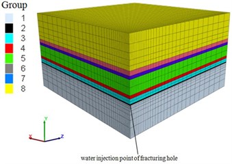
For the boundary conditions, the horizontal and bottom surface was constrained; at the top surface, an additional [MPa] of overburden stress was applied. The vertical stress was set according to the equation . In the horizontal plane, the in-situ stress was set as 2.0 and 1.2 of the overlying strata in the and directions, respectively. The initial pore pressure in the coal seam was set as 2 MPa.
Table 1Main stratigraphic and lithologic parameters of the model
Coal-rock name | Group | [Pa] | [Pa] | [m2] | [kg/m3] | [Pa] | Thickness [m] | |
Sandy mudstone | 8 | 4.8e10 | 9.6e9 | 1.00e-17 | 0.003 | 2400 | 6e6 | 20 |
Protected coal seam | 7 | 3.57e9 | 7.14e8 | 1.00e-15 | 0.021 | 1400 | 2e6 | 2.8 |
Siltstone | 6 | 2.66e10 | 1.22e10 | 1.00e-17 | 0.003 | 2560 | 9.4e6 | 2 |
Medium sand | 5 | 1.65e10 | 1.25e10 | 1.00e-17 | 0.003 | 2600 | 5.7e6 | 9 |
Mudstone | 4 | 1.97e10 | 1.14e10 | 1.00e-17 | 0.003 | 2400 | 4e6 | 2 |
Fine sand | 3 | 3.45e10 | 6.85e9 | 1.00e-17 | 0.003 | 2500 | 5e6 | 3 |
coal seam | 2 | 3.57e9 | 7.14e8 | 1.00e-15 | 0.021 | 1400 | 2e6 | 0.7 |
Sandy mudstone | 1 | 4.8e10 | 9.6e9 | 1.00e-17 | 0.003 | 2400 | 6e6 | 20 |
4. Modeling results of the main fracturing
4.1. Relation between the fracture area and water injection rate
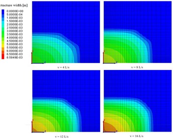
Keeping the volume of injected water fixed at 166.88 m3, the water injection rate was changed and the fractured area at the site was observed. Fig. 2 shows the fractured area after injection in cross sections of the - plane in the quarter-model for four water injection rates. As the water injection rate rises, the fractured area increases gradually. For injection rates of 4 L/s, 8 L/s, 12 L/s, and 16 L/s, the fractured areas are 12060 m2, 13700 m2, 13780 m2, and 14180 m2, respectively. The fractured area around the injection site increased gradually as the water injection rate increased; this is mainly caused by the different filtration rates. Fig. 3 shows the change in fracture volume with time for the various water injection rate cases. As the water injection rate increased, the filtration time of the same volume of fracturing fluid was reduced. The fractured volume increased, resulting in an increase of the fractured area; however, the growth rate of the fractured area decreases because a higher water injection rate produces a higher fluid pressure, which increases the width of the fracture. Thus, although the fracture volume increased significantly the fracture area increased at a slower rate.
Fig. 2z-x cross section of the seam showing the fractured area after fracturing at different injection rates
4.2. Relation between the fracture area and fluid viscosity
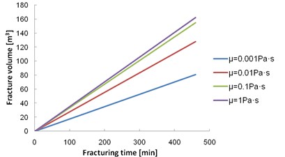
The changes in the fractured area were modeled with various fracturing fluid viscosities for a water volume of 166.88 m3 and water injection rate of 0.00604 m3/s. Fig. 4 shows the fractured areas around the injection site after injection, in the - plane cross section of the quarter-model with different fluid viscosities. The fracture area increases gradually with increased viscosity of the fracturing fluid; for viscosities of 0.001, 0.01, 0.1, and 1 Pa∙s the fractured area is 12920, 14180, 12140, and 9570 m2, respectively. As the fluid viscosity increased, the fractured area expanded and then decreased. Moreover, with higher fluid viscosity the filtration rate decreased sharply, leading to an increase in fracture volume (Fig. 5). However, the higher viscosity reduces the fluid velocity, causing the fractures to broaden, i.e., extend in width rather than in length. Thus, with higher viscosity, the fracture area increases initially and then decreases.
Fig. 3Relationship between the fracture volume and the fracturing time at different injection rates
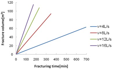
Fig. 4z-x cross-section diagram of the seam after fracturing under different viscosities of the fracturing fluid
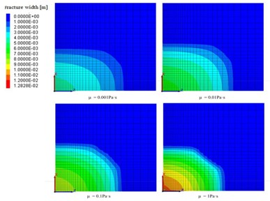
Fig. 5Relationship between the fracture volume and the fracturing time for different viscosities of the fracturing fluid
4.3. Relation between fracturing area and water injection volume
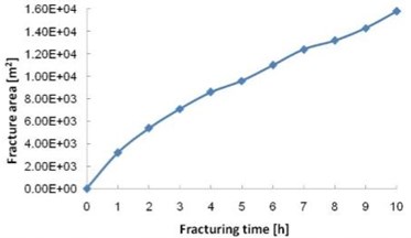
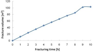
The water injection rate was 0.00604 m3/s and the cross sections show the extent of the fractures between 1 h and 10 h after water injection commenced, at 1 h intervals. As the injection time becomes longer, the fracturing range gradually increases Fig. 6(a). Initially, the fractured area increases quickly because the initial crack area is small and the fluid pressure in the hydraulic fractures is high. After the first 2 h of injection the fractured area increases almost linearly, this is because as you progress through the fracturing, the fracture within the water pressure will gradually stabilized, in the same volume will crack under the condition of water injection rate, linear growth and crack tip slit width is small coke approximation is equal, thus fracturing area will approximate linear growth. Fig. 6(b) shows the growth in fracture volume with increasing water injection period. The fracture volume curve is also mostly linear up to 9 h; the reduced growth at 10 h may be due to the boundary effect in the model.
Fig. 6Variation curves of fracture area and fracture volume with water injection time
a)
b)
5. Conclusions
Based on fracture and porous media fluid-solid coupling theory, we developed a numerical model which could calculate the fracture area of hydraulic fracturing in underground coal mines. The model was used for three-dimensional numerical simulation of hydraulic fracturing in the No. 3111 working area of the coalmine.
We studied the relationship between the fractured area and the injection volume, injection rate, and the viscosity of the fracturing fluids. The fractured area increased with increasing injection rate, however the rate of extension slowed down; the fractured area initially increased and then decreased with increasing viscosity; the fractured area increases rapidly with the increase of the water injection volume at the beginning, then begin to slow, eventually approximate linear growth. The results indicate that the fracturing effect can be enhanced by increasing the water injection volume and injection rate and appropriately increasing the viscosity of the fracturing fluid.
References
-
Dai S. F., Ren D. Y., Chou C. L., Finkelman R. B., Seredind V. V., Zhou Y. P. Geochemistry of trace elements in Chinese coals: a review of abundances, genetic types, impacts on human health and industrial utilization. International Journal of Coal Geology, Vol. 94, 2002, p. 3-21.
-
Zhai C., Yu X., Xiang X. W., Li Q. G., Wu S. L., Xu J. Z. Experimental study of pulsating water pressure propagation in CBM reservoirs during pulse hydraulic fracturing. Journal of Natural Gas and Science Engineering, Vol. 25, 2015, p. 15-22.
-
Zhai C., Li M., Sun C., Zhang J. G., Yang W., Li Q. G. Guiding-controlling technology of coal seam hydraulic fracturing fractures extension. International Journal of Mining Science and technology, Vol. 22, 2012, p. 831-836.
-
Lu Y. Y., Cheng L., Ge Z. L., Xia B. W., Li Q., Chen J. F. Analysis on the initial cracking parameters of cross-measure hydraulic fracture in underground coal mines. Energies, Vol. 8, 2015, p. 6977-6994.
-
Wang W. C., Li X. Z., Lin B. Q., Zhai C. Pulsating hydraulic fracturing technology in low permeability coal seams. International Journal of Mining Science and technology, Vol. 25, 2015, p. 681-685.
-
Song D. Z., Liu Z. T., Wang E. Y., Qiu L. M., Gao Q. Q., Xu Z. Y. Evaluation of coal seam hydraulic fracturing using the direct current method. International Journal of Rock Mechanics and Mining Science, Vol. 78, 2015, p. 230-239.
-
Liu Y., Xia B. W., Liu X. T. A novel method of orienting hydraulic fractures in coal mines and its mechanism of intensified conduction. Journal of Natural Gas and Science Engineering, Vol. 27, 2015, p. 190-199.
-
Fu X. Study of underground point hydraulic fracturing increased permeability technology. Journal of China Coal Society, Vol.36, 2011, p. 1317-1321. (in Chinese)
-
Yuan Z. G., Wang H. T., Hu G. Z., Fan X. G., Liu N. P. Numerical simulation of hydraulic fracturing of crossing borehole and its engineering application. Journal of China Coal Society, Vol. 37, 2012, p. 109-114, (in Chinese).
-
Wang T., Zhou W. B., Chen J. H., Xiao X., Li Y., Zhao X. Y. Simulation of hydraulic fracturing using particle flow method and application in a coal mine. International Journal of Coal Geology, Vol. 121, 2014, p. 1-13.
-
Zhou L., Hou M. Z., Gou Y., Li M. T. Numerical investigation of a low-efficient hydraulic fracturing operation in a tight gas reservoir in the North German Basin. Journal of Petroleum Science Engineering, Vol. 120, 2014, p. 119-129.
-
Zhou L., Su X. P., Hou Z. M., Lu Y. Y., Gou Y. Numerical investigation of the hydromechanical response of a natural fracture during fluid injection using an efficient sequential coupling model. Environmental Earth Sciences, Vol. 75, Issue 1263, 2016, p. 1-17.
-
Zhou L., Chen J. C., Gou Y., Feng W. T. Numerical investigation of the time-dependent and the proppant dominated stress shadow effects in a transverse multiple fracture system and optimization. Energies, Vol. 10, Issue 83, 2017, p. 1-21.
About this article

