Abstract
This paper presents a modified rigid cross beam method to study the lateral distribution of multi-I beam composite curved bridge with slip effect. First, the effective stiffness expression of single composite curved beam with slip effect were established and calculated by the FEM. Secondly, the lateral load distribution of multi-I beam composite curved bridge is obtained by substituting the effective stiffness of the main composite curved beam into the rigid cross beam method. Finally, The FEM numerical examples show that this method can accurately describe the load distribution characteristics of multi-I beam composite curved bridge with slip effect.
1. Introduction
The application of multi-I beam composite curved bridge increases gradually, which shows very complex structural behaviour since the coupling effect of axial, flexural and torsional deformation. In addition, the shear connectors generally permit the development of only partial composite action between the individual components of the member, and their analysis requires the consideration of the interlayer slip between the subcomponents. Therefore, as important parts of bridge design, it is of great significance to study the lateral distribution of this kind of bridge under complex structural behavior.
So far, the lateral distribution researches of multi-beam composite curved bridge analysis, correlative research work is relative scarce. Huang et al. [1], conducted experiments and numerical analysis to investigate the lateral distribution behavior of the oblique composite beam with large angle. The experiment results were compared with the finite element results and norm of AASHTO in their study. Samaan et al. [2], using a finite element method, studied the structural responses of two-equal-span continuous curved box-girder bridges. Barr and Amin. [3] provided a finite element model to investigate the effects of girder spacing, span length, overhang distance and skew angle on the shear live-loud distribution factor. Harris and Gheitasi [4] presented an analytical approach for determining lateral load distribution characteristics of beam-slab type bridges, using classical plate theory. A modified method was developed [5] based on the rigid-jointed girder method considering the different main girder stiffnesses and the space between the original bridge and the widened bridges. Ma et al. [6] provided a modified prediction method of eccentric lateral load distribution for investigating the lateral load distribution on continuous composite box girder bridge with corrugated steel webs. It shows in their study that an improved plane model which considering the box girder torsional stiffness of the box girder can be introduced to solve the spatial problem by using modified method of eccentric lateral pressure.
The researches have been accomplished in regard to the lateral load distribution of the multi-I beam composite curved bridge, however, limited researches have focused on the multi-beam composite curved bridge with partial shear interaction. Xiang et al. [7] provided a modified rigid transverse beam method and rigid connected beam method for the multi-box composite beam bridges by considering the interface slippage’s effect. The results show that the modified rigid connected beam method considering slippage effect is effective to calculate the lateral load distribution of mid-span cross section in multi-box composite beam bridge. In the present paper, a modified rigid cross beam method is developed to study the lateral distribution of composite curved bridge with multi-I beam with slip effect. The numerical results are compared with the FEM.
2. Effective stiffness of single composite curved I-beam
2.1. The effective stiffness with partial interaction
In general, for a single composite I-beam with partial shear connectors, the actual value of effective stiffness is the value between no shear connection and rigid shear connection. So, the interpolation method can be adopt to calculate the effective stiffness of partial shear connectors, namely:
where, and , and , and are the effective bending stiffness and torsional stiffness of the I-beam with partial interaction, no-shear interaction, rigid shear connection, respectively. and are the interpolating function. According to the Ref. [8], , , and can be calculated by the following equations:
where and , and , and , and , and , are the elasticity modulus, bending inertia moment, shear modulus, torsional inertia moment, sectional area of the concrete slab and the I-steel girder, respectively. is distance between the centroid of the concrete slab and the steel girder. and are the width and the thickness of the concrete slab. is the thickness of the steel girder. is the coefficient of the tensional stiffness.
2.2. The stiffness interpolating function
According to the Ref. [8], the effective bending stiffness for the straight single composite beam with simply supported ends can be express as:
where , , and
The Eq. (4) can be rewritten as:
Assume that the interpolating function of the stiffness has the similar expression with the single straight composite beam, which are:
where, and are the coefficient of the bending stiffness and torsional stiffness interpolating function.
3. The coefficient of the stiffness
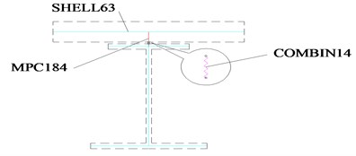
A FEM (finite element model shown in Fig. 1) proposed by Erkmen [9] and Wonseok [10] is adopted to determine the coefficient of bending stiffness and torsional stiffness ( and ). Both the concrete slab and steel I-girder are modeled as 4-node shell elements in the model. The connections between the slab and I-girder (shown in Fig. 2) are simulated by multiple-point constraints (MPC). The spring elements are used in the tangential direction and the radial direction to allow for the possibility of movement.
Fig. 1FEM model of single composite curved beam
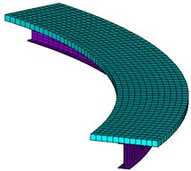
Fig. 2Element connection of the composite beam
If the influence of curvature radius for the bending stiffness coefficient is small, the coefficient of the single curved composite I-beam can be taken as the coefficient (Eq. (5)) of the single straight composite I-beam.
Fig. 3Section sizes of the composite beam (unit: m)
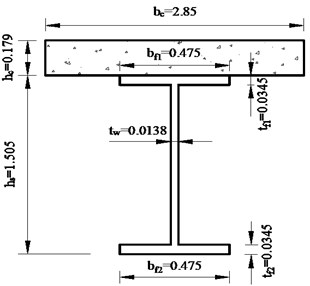
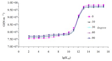
To demonstrate the influence of curvature radius for the coefficient of the bending stiffness, consider a simply supported single curved composite I-beam subjected to uniform load with beam length 29.2 m. The other parameters in the model are shown in Table 1 and Fig. 3. The effective stiffness of the composite beam is calculated under different central angle. The results (Fig. 4) show that the coefficient of composite curved beam can be taken as the coefficient of composite straight beam because the influence of central angle on the effective stiffness is very small. So, we take as the coefficient in Eq. (5).
To quantify the , the torsional stiffness interpolation function is calculated with different design parameters shown in Table 2. According to the calculation results in Fig. 5, the torsional stiffness interpolation function can be taken as through curve fitting.
Table 1Material properties of the composite beam
Parameters | Concrete slab | Steel girder |
Elasticity modulus (MPa) | 3.45×10⁴ | 2.06×10⁵ |
Poisson’s ratio | 0.167 | 0.3 |
Table 2Design parameters of composite beam
Parameters | Values (Model 1) | Values (Model 2) | Values (Model 3) |
Thickness of the concrete slab (m) | 0.12 | 0.24 | 0.36 |
Height of the steel girder (m) | 0.66 | 1.32 | 1.98 |
Fig. 4Effective stiffness of the composite beam
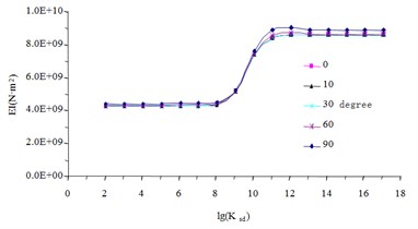
a) Bending stiffness
b) Torsional stiffness
Fig. 5The curves of torsional stiffness interpolation function
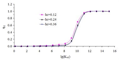
a) The when the thickness is changed
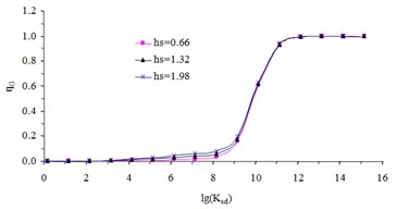
b) The when the height is changed
4. The coefficient of the stiffness
4.1. The stiffness interpolating function
To obtain calculation formula of lateral load distribution for multi-I beam composite bridge, the traditional rigid cross beam method is modified the interface slip effect. Substitute the deformation constant of the single composite I-beam into the formula of rigid cross beam method, the lateral load distribution for multi-beam composite bridge considering the interface slip effect can be get, which are:
where and are the value of lateral load distribution influence line under the vertical load and torque load, respectively. Where other parameters can be refer to the Ref. [11].
4.2. The stiffness interpolating function
According to the relation between mid-span bending moment and external load [12], the mid-span moment of main beam can be got after obtain the lateral load distribution influence line of main beam :
where is the curvature radius of main beam , is the central angle of the curved composite beam. The influence line of lateral load distribution for bending moment is:
5. Numerical examples
To validate the accuracy of the lateral load distribution presented in this paper, a multi-I beam composite curved bridge with simply supported ends (Fig. 7) is taken as an example. The bridge is composed of five pieces of main beam. The central angle is 30°. 50 m, 52.85 m, 55.7 m, 58.55 m and 61.4 m are the center radius of the main beam, respectively. Three diaphragms are set in middle diaphragm and either side of the bridge, respectively. In this example, the material properties, geometric properties are list in Table 3. The shear stiffness is 106 N/m for a stud, and 61 studs are arranged along the whole span with equal distance. Finite element model (Fig. 7) described here with the same way like single composite curved beam model.
Fig. 7Five-beam composite curved bridge model
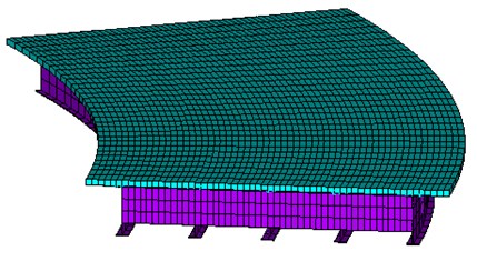
Table 3Material properties and section sizes of main beams
parameters | Elasticity modulus (MPa) | Poisson’s ratio | Sectional dimension (m) |
Concrete slab | 3.45×10⁴ | 0.167 | |
Steel girder | 2.06×10⁵ | 0.3 |
Table 4 shows the lateral mid-span moment distribution factors of main beams based on the finite element method, this paper solution, rigid cross beam method and the error between them. From the result list in Table 4, we can see:
1) Big errors are obtained from the finite element analysis and the rigid cross beam method with no interface slip. The mean error is found to be 17.4 % happened at the fifth main beam. The results show that the influence of interface slip to the lateral mid-span moment distribution factors can’t be ignored for the week composite curved bridge with shear connection.
2) Close agreement is observed from the finite element analysis and this paper solution. The mean error is found to be –3.6 % happened at the first main beam.
Table 4Lateral moment distribution factors of main beams
Beam number | FEM | This paper solution | Error (%) | Rigid cross beam method | Error (%) |
1 | 0.594 | 0.573 | –3.6 | 0.630 | 6.1 |
2 | 0.517 | 0.512 | –1.0 | 0.500 | –3.3 |
3 | 0.552 | 0.551 | –0.2 | 0.558 | 1.2 |
4 | 0.598 | 0.600 | 0.3 | 0.654 | 9.3 |
5 | 0.668 | 0.666 | –0.4 | 0.785 | 17.4 |
Notice: Error = (Rigid cross beam method or this paper solution)/FEM *100 % | |||||
6. Conclusions
In this paper, a modified rigid cross beam method has been developed and presented for the lateral distribution of multi-I beam composite curved bridge with interface slip. The finite element method is used to determine the stiffness interpolation coefficients of single composite curved beam and verify the lateral distribution calculation of multi-beam composite curved bridge. The numerical examples show that the influence of interface slip to the lateral mid-span moment distribution factors can’t be ignored for the composite curved bridge with week shear connection, and the lateral distribution got by rigid cross beam method considering slip effect is in good agreement with that by finite element static analysis, which indicates that this method can accurately describe the load distribution characteristics of multi-beam composite curved bridge.
References
-
Huang H., Shentong H. W., Chajes M. J. Load distribution for a highly-skewed bridge: testing and analysis. Journal of Bridge Engineering, Vol. 9, Issue 6, 2004, p. 558-562.
-
Samaan M., Sennah K., Kennedy J. B. Distribution factors for curved continuous composite box-girder bridges. Journal of Bridge Engineering, Vol. 10, Issue 6, 2005, p. 678-692.
-
Barr P. J., Amin M. N. Shear live-load distribution factors for I-girder bridges. Journal of Bridge Engineering, Vol. 11, Issue 2, 2006, p. 197-204.
-
Harris D. K., Gheitasi A. Implementation of an energy-based stiffened plate formulation for lateral load distribution characteristics of girder-type bridges. Engineering Structures, Vol. 54, Issue 3, 2013, p. 168-179.
-
Nie Jianguo, Zhang Xiaoguang, Fan Jiansheng, et al. Transverse distribution coefficient of concrete bridges widened with steel-concrete composite beams. Journal of Tsinghua University (Science and Technology), Vol. 50, Issue 6, 2010, p. 805-809.
-
Ma Lei, Zhou Linyun, Wan Shui Lateral load distribution of continuous composite box girder bridge with corrugated steel webs. Journal of Highway and Transportation Research and Development, Vol. 30, Issue 5, 2013, p. 58-62.
-
Xiang Yiqiang, He Yuliang, Liu Lisi, et al. Lateral load distribution of multi-box steel-concrete composite girder bridges for considering slipping effect. Journal of Harbin Institute of Technology, Vol. 44, Issue 8, 2012, p. 113-118.
-
Girhammar U. A., Pan D. H. Exact static analysis of partially interaction composite beams and beam-columns. International Journal of Mechanical Sciences, Vol. 49, Issue 2, 2007, p. 239-255.
-
Erkmen R. E., Bradford M. A. Nonlinear elastic analysis of composite beams curved in-plan. Engineering Structures, Vol. 31, Issue 7, 2009, p. 1613-1624.
-
Chung W., Sotelino E. D. Three-dimensional finite element modeling of composite girder bridges. Engineering Structures, Vol. 28, Issue 1, 2006, p. 63-71.
-
Yao Lingsen Curved Beam. China Communications Press, Beijing, 1994.
-
Fan Lichu Bridge Engineering. China Communications Press, Beijing, 2012.
About this article

