Abstract
A new scour numerical model composed of two modules is proposed here. The two modules are detailed Reynolds-average Navier-Stokes flow module and sediment transport and resultant scour module. The flow module uses horizontally regular grid at the bed but partial grid concept in the vertical direction. The sediment module operates entrainment, and deposition of suspended sediment. The entrainment of sediment is computed by a new empirical equation; the major independent variables of which are the jet flow velocity and the bed shear stress. The model is applied to a laboratory scour experiment around a circular cylinder at Kookmin University, and shows satisfactory agreement with measurements.
1. Introduction
Modelling scour require a special grid system to allow gradual evolvement of local scour hole, which involves steep slope and sudden slope change, in contrast to modelling wide area morphologic change on coasts. There have been a few trials to overcome this problem.
First, a very fine traditional regular grid can be used. However, very fine grid involves high computation cost to resolve bed roughness. Second, a nesting or coupling technique to combine coarse and fine grids can be used to reduce computational load. However, this also requires complicated joint treatment, and does not dramatically reduce computational load. Third, a moving boundary-fitted, unstructured, or fractional grid around solid boundary can be used. However, this measure leads to heavy grid-related mid-processing, and is not free from numerical error due to non-straight grid lines, or triangular, trapezoidal, or octagonal grids.
A simple grid system, regular in plan, moving fractional in the vertical direction, is adopted here to simulate scour evolution around vertical structures.
Scour evolution can be explained by either bed load, suspended sediment load or both. There are arguments that it is quite delicate to define bed load and suspended load, especially if scour evolves with steep slope, or the bed is covered with bed forms. The bed load gradient produces imminent morphological change, while the resuspension rate gradient and deposition rate gradient produce wider morphologic change due to phase lag between suspension, transport, and settling. If bed is covered with bed forms like ripples, it is still acceptable to treat the bed load as suspended load once the sediment particles leave the ripple crest, see Kim [1]. In this paper only suspended load is considered, so that the phase shift between erosion and deposition is well represented.
Existing sediment entrainment or pickup rate from the bed surface has been described as a function of the bed shear stress [2]. Our approach here is resolving short wave phase, and therefore we don’t need wave-phase-average entrainment rate, but instantaneous entrainment rate. Existing instantaneous sediment entrainment rate formulas are all empirical [3-5], and could be represented by an equation as:
where is the entrainment rate; , are specific coefficients for a given sediment material, is the instantaneous bed shear stress, and is the critical shear stress for sediment movement initiation. If bed sediment is non-cohesive, and its median diameter is known, the above coefficients and be found from an existing formula.
A fundamental defect of the above equation is that the equation cannot take into account the effect of local pressure enhanced by jet flow. Eq. (1) is suitable for fluid flows which are more less flat like river flows or coastal flows. It is quite obvious that sediment is eroded at the center of a circle if a jet flow hits the seabed in the normal direction, while simulation with the above equation may result in donut-type erosion, which is wrong. Flow around a vertical structure shows sheet-type jet flow along the surface of the structure which soon turns its direction, and generate horseshoe vortex.
Sumer and Fredsoe [6], Dixen et al. [7] and Sumer et al. [8] proposed a methodology to treat the extra entrainment due to jet flow, or horseshoe vortex in front of structures, Sumer et al. regarded the extra entrainment as a result of enhanced turbulence, and modified their bed load formula by adding a term including turbulent energy. However, the horseshoe vortex is a turbulence-average flow behavior, and thus quantifying the extra entrainment by the turbulent energy could not explain the phenomena properly. Explanation of the extra entrainment by jet flow seems to be more appropriate. Local erosion due to jet flow has been studied by experiments or numerical simulations [9-11].
2. Numerical model setup
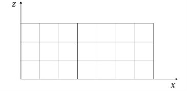
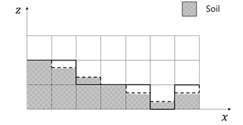
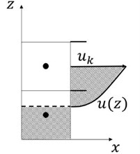
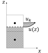
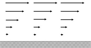
The numerical model WCFLUME [12, 13] is composed of two modules, i.e. flow and sediment transport modules. The flow module solves extended governing equations and difference equations for three-dimensional domain from two-dimensional vertical domain. Model grid is basically regular rectangular, see Fig. 1. The horizontal grid is regular, see Fig. 2(a). The bed morphology is expressed as steps, the levels of which do not agree with grid border levels, see Fig. 2(b). The bed shear stress at the bed surface is computed by using the logarithmic law and the nearest available velocity above the bed, see Fig. 3.
Fig. 1Model grid
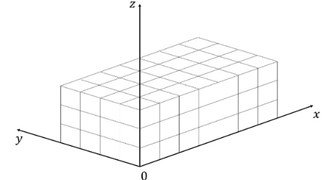
Fig. 2Modification of grid in the vertical direction
The sediment transport module solves the transport and dispersion with the water column [12, 13]. The sediment entrainment into the water column is contributed by both the instantaneous bed shear stress, and the local jet. To take into account the extra-entrainment due to jet effect pressure could be used, but it is not easy to extract the jet-induced pressure increment from the total pressure field which includes both static and dynamic pressure. Alternately the vertical velocity may be used as the representative variable of the jet towards seabed. The vertical velocity just above the seabed is the most adequate to be linked to the entrainment rate instead of pressure. A weak point of using the vertical velocity above the seabed is that it is grid-size dependent. Velocity reduction gradient in the vertical direction would be the most appropriate representative variable to express the extra entrainment. In this paper the vertical velocity gradient at the seabed is adopted. Then the extra entrainment rate is expressed as:
where is the entrainment rate due to jet flow, is the vertical fluid velocity speed towards the seabed, and is the critical vertical fluid velocity speed for initiation movement of sediment. A difference equation replaces the above differential equation as:
where is the downward vertical fluid velocity speed at the nearest grid border from the bed. The coefficients in the above equation should be found from measurements available. Coefficients used are: , . Then:
Fig. 3Assumption of horizontal velocity distribution in the vertical direction
3. Model application
The present model system WCFLUME was applied to a laboratory experiment at Kookmin University [14]. A vertical cylinder stands in a current flume, see Fig. 4.
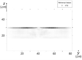
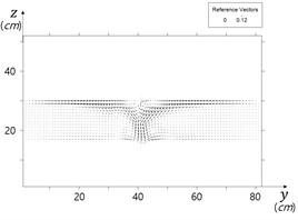
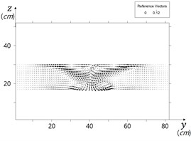
Model results show three-dimensional flow pattern around the cylinder, and minor surface undulation around the cylinder. Horseshoe vortex ring developed around the cylinder foot. Computed flow field at the bed in () domain in Fig. 5, and flow field in Fig. 6 in a section show horseshoe vortex at an intermediate stage of scour. The vortex could be expressed by vorticity, , that is:
An interesting three-dimensional circulation behind the cylinder has been reported by Sumer et al. [8]. Computed flow fields in the sections show this circulation pattern, see Fig. 8. Because the simulation includes free surface, computed water surface level shows the back water phenomena.
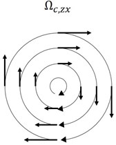
However, vorticity describes angular rotating speed of a fluid element, and thus gives positive value for even straight shear flow, see Fig. 7. If we want to extract rotationality with curvature, say curvy vorticity, we could introduce the following properties, and :
Fig. 4Model setup
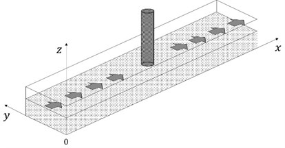
Fig. 5Computed bed flow field showing horseshoe vortex in front of cylinder
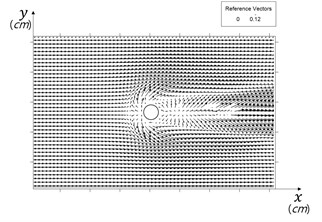
Fig. 6Horseshoe vortex in front of cylinder
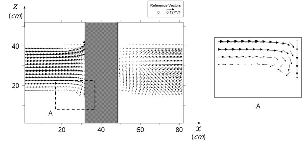
Fig. 7a) Vorticity for shear flow b) curvy vorticity
a)
b)
Computed vorticity and curvy vorticity are shown in Fig. 8. The curvy vorticity well describes the strength of rotationality, and the position of horse shoes vorticity, compared to traditional vorticity.
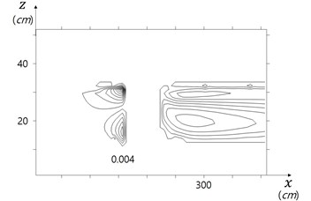
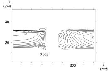
Computed contributions of the vertical gradient of the vertical velocity the bed shear stress and are shown in Figs. 10, and 11, and their sum is shown in Fig. 12. It is obvious that jet flow heavily contributes scour evolvement in front of the cylinder.
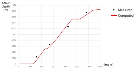
Computed time evolution of the scour depth at cylinder foot is shown in Fig. 13. Scour depth develops with step-shape, which may have been resulted from the partial vertical grid treatment.
Fig. 8Traditional vorticity vs curvy vorticity
a) Vorticity for shear flow (1/s)
b) Curvy vorticity (1/s)
Fig. 9Three-dimensional flow behind cylinder
a) 0.229 m behind cylinder
b) 0.259 m behind cylinder
c) 0.289 m behind cylinder
Fig. 10Scour depth due to jet flow
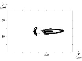
Fig. 11Scour depth due to bed shear stress
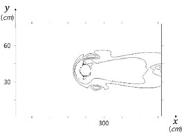
Fig. 12Total scour depth
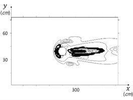
Fig. 13Time evolution of scour depth
4. Conclusions
A numerical model system, WCFLUME [12-13], was developed for simulation of local scour around coastal structures. The system uses a regular three-dimensional parallelepiped grid. The seabed level stays between grid border lines.
Sediment entrainment is expressed by a new equation which includes both existing empirical term composed of the bed shear stress, and a new term composed of the vertical gradient of the vertical velocity, which represents the jet effect.
The model system was applied to a scour around a vertical circular cylinder sandy bed. Model simulated horseshoe- vortex-induced scour hole upstream side of the cylinder, and bed-shear-stress-induced scour hole at both sides of the cylinder reasonably well. Empirical coefficients involved in simulation may further need to be assessed with more data.
References
-
Kim H., O’Connor B., Shim Y. Numerical modelling of flow over ripples using sola method. International Conference on Coastal Engineering, 1994, p. 2140-2154.
-
Van Rijn L. C. Unified view of sediment transport by currents and waves. IV: Application of morphodynamic model. Journal of Hydraulic Engineering. American Society of Civil Engineers, Vol. 133, Issue 7, 2007, p. 776-793.
-
Partheniades E. Results of Recent Investigations on Erosion and Deposition of Cohesive Sediments. Sedimentation, Fort of Collins, Colorado, 1972, p. 20-39.
-
Nielsen P. Sheet flow sediment transport under waves with acceleration skewness and boundary layer streaming. Coast Engineering, Vol. 53, 2006, p. 749-758.
-
Van Rijn L. C. Sediment pick-up functions. Journal of Hydraulic Engineering, American Society of Civil Engineers, Vol. 110, Issue 10, 1984, p. 1494-1502.
-
Sumer B. M., Fredsoe J. The Mechanics of Scour in the Marine Environment. World Scientific Publishing Co. Pte Ltd., Vol. 17, 2002.
-
Dixen M., Sumer B. M., Fredsoe J. Numerical and experimental investigation of flow and scour around a half-burie sphere. Coastal Engineering, Vol. 73, 2013, p. 84-105.
-
Sumer B. M. A Review of recent advances in numerical modelling of local scour problems. 7th International Conference on Scour and Erosion, Australia, 2014, p. 61-70.
-
Qian Z. D., Hu X. Q., Huai W. X., Xue W. Y. Numerical simulation of sediment erosion by submerged jets using a Eulerian model. Science China Technological Sciences, Vol. 53, Issue 12, 2010, p. 3324-3330.
-
Siteur W. J. Sedimentation-Velocity in Jet Induced Flow. M.Sc. Thesis, Delft University of Technology, 2012.
-
Hunter T. N., Peakall J., Unsworth T. J., Acun M. H., Keevil G., Rice H., Biggs S. The influence of system scale on impinging jet sediment erosion: observed using novel and standard measurement techniques. Chemical Engineering Research and Design, Vol. 91, Issue 4, 2013, p. 742-734.
-
Kim H., Baek S.-W., Hwang D.-H., Lee G.-P., Jin J.-Y., Jang C.-H. Intra-wave-phase cross-shore bed profile modelling by using boundary-fitted moving grid. Journal of Mathematical Models in Engineering, Vol. 24, 2016. (in Press).
-
Kim H. WCFLUME: A CFD for Wave and Current. http://blog.naver.com/cfd3d, Kookmin University, 2016.
-
Kim H., Kim I., Lee S., Hong T. Laboratory experiments on scour around flat circular buckets for high waves and strong current at Wido Windfarm, Westsouth Sea, Korea. International Conference on Scour and Erosion, Vol. 8, 2016, p. 81.
About this article

This research is a part of the Project titled “Development of Coastal Erosion Control Technology”, funded by the Ministry of Oceans and Fisheries, and “Installation and Corroborative Study for Internal Power Network of Ocean Wind Power Plant”, funded by the Institute of Energy Technology Evaluation and Planning, Korea.
