Abstract
Excessive vibration can cause engine fault, so the engine vibration monitoring and control is particularly important to flight safety. With the simulation platform of hardware in loop of the engine control system, the ability to handle the vibration of the engine controller can be verified. It can effectively reduce the development cost and shorten the development cycle. This paper is a result of extensive research on the vibration signal modeling and the interface simulation technology of engine, in the vibration control experiment of hardware in loop; and a universal interface simulator has been designed. The interface simulator can receive multi-channeled signal in a wide-range of values, and can also simulate different kinds of signals, simplify the signal acquisition and conditioning circuit of the electronic controller. This simulation provides a good platform for the research of engine vibration control.
1. Introduction
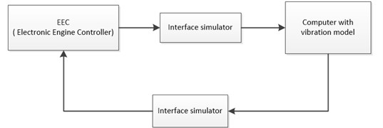
Owing to the complicated load and variable working environment of the aero-engine, there are many vibration signals in actual work, some of these signals are associated with the inherent characteristics of the system, others are with the failure which has occurred or is about to occur. In the above research of engine vibration monitoring, the control system hardware-in-loop test is an important part. The hardware-in-loop real time test platform figure out the overload state and simulate the vibration signal based on the engine vibration model, then the overload state will be transmitted to the electronic controller, and the controller then takes measures to reduce the vibration of the engine. The principle is shown in Fig. 1.
Fig. 1The principle of hardware-in-loop experiment
According to the needs of vibration monitoring hardware-in-loop test, this paper designs an interface simulator based on Ethernet communication. The interface simulator has the functions of receiving of vibration signal, data exchange with the model computer, simulation of the vibration signal and so on. The interface simulator with strong commonality has a plurality of analog signals and digital signal input channels, and is compatible with a variety of signal inputs, Ethernet communication has the characteristics of good real-time performance and large amount of data, so it can be used in real-time monitoring of engine vibration. In this case, the electronic controller can respond to the engine excessive vibration problem in time. At the same time, the interface simulator which is designed in this paper can simulate the multi-channel vibration signal and find real-time solution based on the vibration model, so as to achieve high quality vibration simulation. In addition, the simulator has dual channel pulse width modulation (PWM) signal output. It can simulate the torsional vibration signal by comparing the output phase, which also provides a new way for the study of torsional vibration of engine.
2. Design of interface simulator
Interface simulator is a bridge between the controller and the computer which has the vibration model. It mainly has two functions: one is the perception of vibration signals; the other is the simulation of vibration signals. The performance of an interface simulator has a direct impact on the quality of simulation. The interface simulator designed in this paper mainly includes power module, CPU module, input module, communication module and output module.
2.1. Power module
The different modules of the interface simulator need different power supplies, so different power supplies are designed according to different circuits. The power supply voltage is 24 V, and a WRB2412S-3WR2 chip is used to convert 24 V into –12 V, while using a WRB2412MD-10W chip to convert 24 V into 12 V, they supply power for the analog input and output channels. LM2576-5V chip is used to convert 24 V voltage into 5 V, which can supply power for the DAC chip. An AMS1117-3.3 chip is used to convert 5 V into 3.3 V, supplying power for digital input and output channels and the TM4C1294NCPDT chip.
2.2. CPU module
The Interface simulator uses a TM4C1294NCPDT as CPU, which is made by Texas Instruments. This ARM chip has powerful functions, and it has 256 KB flash and 1 MB SRAM, eight 32-bit counter, four PWM generator and two 12- bit ADC, etc. In addition, it also integrates MAC/PHY Ethernet, which supports 10 MB or 100 MB communication rate, which is better than the chip with only serial communication module and has better real-time performance. It has better real-time performance than the serial communication.
The peripheral circuit uses a 25 MHz crystal to provide the external clock for the TM4C1294NCPDT chip, and the internal system clock can reach 120 MHz by frequency doubling. It can meet requirements of different Peripherals by dividing or doubling the frequency of the system clock.
2.3. Input module
According to the frequency of vibration signals, different kinds of sensors are used for measurement, and the acceleration sensor is usually used to measure the vibration of aero-engines. Some acceleration sensors cannot obtain the voltage signal directly, but they can obtain the charge signal, such as the piezoelectric accelerometer sensor. Therefore, it is essential to preprocess before the AD sampling. Generally, the perception of vibration signal includes sensor measurement, converter pretreatment, and A/D sampling, the principle of which is shown in Fig. 2.
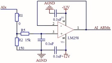
The input module includes two parts: analog output channel and digital input channel. The analog input channel is designed based on the common voltage signal, current signal and the voltage signal after pretreatment. Its input has ranges of 0-20 mA, 0-5 V and 0-10 V, and the signal will be converted to 0-2.5 V standard voltage signals after conditioning. Positive and negative power supplies are used in amplifier circuits to ensure that the output is 0 when the input is 0. In order to meet the requirements of a wide range of signal input, this paper uses a combination of resistor1 () and resistor2 () to make it, as shown in Fig. 3.
When is zero, current signals can be obtained: .
When is not zero, voltage signals can be obtained: .
Where, is the obtained voltage, is the input current and is the input voltage.
Considering the engine vibration monitoring not only deal with the vibration signal, but also deal with operating parameters and flight parameters related to engine, so this module is designed to have 16 input channels, which can meet the requirements of engine monitoring. Therefore, the voltage obtained by each channel can be written as follow:
where, is the obtained analog signal, is analog input signal, subscript is the channel number, it can be 1 to16.
In addition to vibration signals, operating and flight parameters. There are some signs indicating the working state of the switching signal, such as “super vibration warning lights” and so on. There are some switching signals indicating state of the engine, such as “Excessive vibration warning lights” and so on.
The high or low voltage level represents two different states. The interface simulator collects these signals, converts them into digital “0” or “1”, and sends to the computer with model. In order to be compatible with different electrical switches, the input voltage range should be as large as possible. In this paper, the maximum voltage of digital input channel is design to 24 V, while the ARM chip pin input is only 0-3.3 V, so the optical isolation technology is used to convert the 24 V drive voltage into 3.3 V. Besides, switching between high or low voltage can be achieved with a jumper.
Fig. 2The procedure of Vibration signals perception
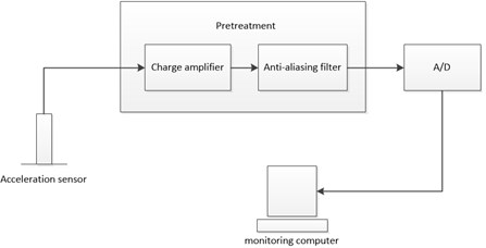
Fig. 3Schematic diagram of the analog input channel
2.4. Communication module
TM4C1294NCPDT chip integrated MAC/PHY Ethernet, support 10 MB and 100 MB communication rate. It has better real-time performance compared with the common serial communication. A RJ45 network port with transformer is connected with the related pins of the chip to realize the Ethernet communication. As shown in Fig. 4.
The interface simulator uses LwIP protocol stack to realize Ethernet communication. It is an independent and simple implementation of the TCP/IP protocol. This protocol stack has a complete TCP/IP function, but the consumption of the microprocessor resources is very low.
2.5. Output module
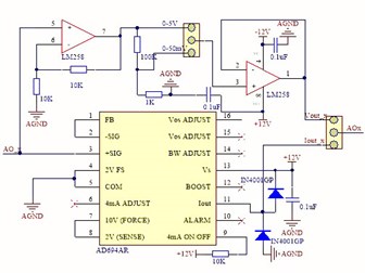
The output module is composed of the analog signal output channel, the digital signal output channel and the frequency signal output channel. The vibration information is calculated by computer and be sent back to the chip. There is no integrated DAC chip in TM4C1294NCPDT chip, so the ARM chip needs two DAC7568 chips, which can be connected with the 16 analog output channels. In order to ensure the simulation quality of the vibration signal, SSI (Synchronous serial interface) is used to provide the real time communication. DAC output voltage is in a range of 0-2.5 V, this paper uses a dedicated V/I converter AD694 chip to make voltage signal into 0-20 mA current signal, which can improve the stability of the signal. Amplifier is used to double the voltage to 0-5 V voltage output. Then a resistor divider can be used to provide the 0-50 mV voltage output. The practical implementation is shown in Fig. 5.
Fig. 4Schematic diagram of the Ethernet communication
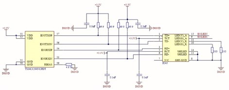
Fig. 5Schematic diagram of the analog output channel
The digital output channel is mainly used to output some high or low voltage level, which indicates the state of the engine. Some working states can be obtained by the model, and the electronic controller will take action according to these states. The digital signal output channel is divided into two parts: one part is outputting directly by ARM through a 74LS244 chip, the other part is the contact output module. When the ARM output is high, the transistor is switched on and the relay is closed at this time. When the ARM output is low, the transistor cut off, and the relay is disconnected.
In addition, the output module also contains two Frequency outputs. These two outputs are connected to the PWM pin of the ARM chip through a buffer. By programming the duty and period, a simulation of speed signal can be realized. They can also simulate a torsional vibration signal with a PWM comparator.
The product of the interface simulator designed in this paper is shown in Fig. 6(a), and the whole condition monitoring of engine vibration and hardware in the loop simulation platform is shown in Fig. 6(b).
Fig. 6Interface simulator and experimental platform
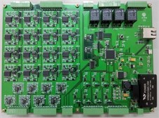
a)
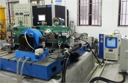
b)
3. Modeling and simulation
3.1. Modeling of vibration signals
A high pressure rotor Dynamic model of aero engine can be expressed as follows:
where, is rotational speed of high pressure rotor, is rotary inertia of high pressure rotor, is residual moment.
Here, only considering the vibration of high pressure rotor of the engine, the model can be simplified into:
In the Eq. (3), is the overload of the engine vibration, is the vibration coefficient, is the DC component, is the unbalance amount, is the phase of the vibration frequency band, is the amplitude of vibration interference; is interference phase.
Simplified mathematical model of vibration sensor is described as below:
where, is voltage output of the sensor; is sensitivity.
A charge signal of vibration can produce current signals by conditioning, and the charge signal is:
In the Eq. (5), is the reference capacitor, is the charge signal by conditioning. In the Eq. (6), is the generated current signal, , , and are uncertain signals generated by external disturbance.
The charge signal of vibration collected by the controller is:
The voltage of the sampling capacitor of the electronic controller is:
where, is the sampling capacitor, and are uncertain signals generated by the external disturbance.
With the interface simulator, the intermediate pretreatment can be omitted, and the vibration signals can be output to the electronic controller directly in the form of the voltage. A voltage value can be converted to an amplitude value by a certain scale:
where, is the voltage which the interface simulator output to the controller directly, is the conversion coefficient.
3.2. Simulation and analysis
The interface simulator is used to generate a vibration signal, which is transmitted to the engine electronic controller. Then the controller collects the signal and analyzes it. The accuracy and reliability of the interface simulator can be verified when comparing with the mathematical model. In order to facilitate the verification experiment, the expression of overload signal in the Eq. (3) is simplified and assigned:
where, and are amplitude after simplification, is the external disturbance, and can be taken as a random Gauss white noise signal:
According to the actual vibration of an aero engine, the parameters in the Eq. (10) can be assigned as follow: 150 Hz, 0, 4.5, 2, 1.2, 0.6, 0.3, 0.1.
In addition, the interface simulator output is selected the range of 0 to 5 V, which means the maximum output amplitude is 5 V.
Fig. 7Chart of the simulation result
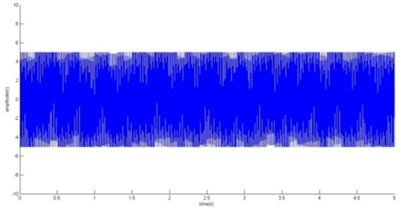
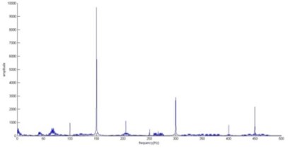
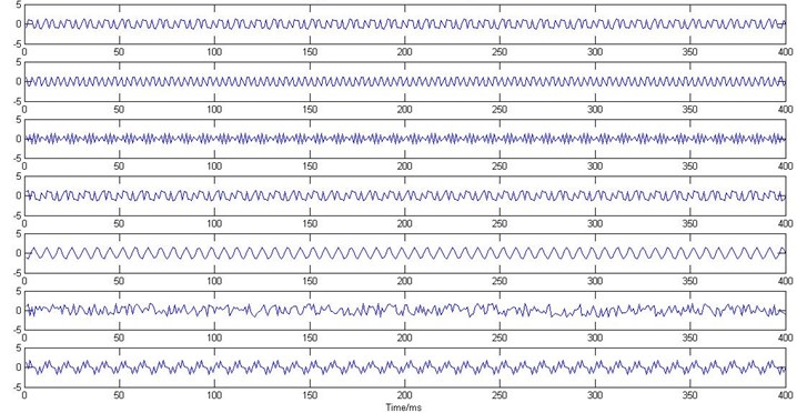
Fig. 8Signals obtained after blind source separation
The result of simulation has been shown in Fig. 7(a). These are the voltage values collected by the electronic controller in 5 seconds. The result shown in Fig. 7(b) can be achieved by dealing with the voltage values with fast Fourier Transform. The frequency of the vibration signal analyzed in frequency domain is consistent with the assumed values in the model, so the accuracy of the interface simulator gets proved. High order signal does not appear in Fig. 7, because their amplitude is too small and the sampling frequency is limited. From the perspective of external interference, the interference in this frequency band is very small, and the reliability of the interface simulator is very good.
For the second harmonic and the non-integral harmonic, FFT is difficult to determine the vibration caused by the high pressure rotor, or the vibration caused by the low pressure rotor. A blind source separation method is also needed, and the analog signal can be obtained as a result of ICA processing, which is shown in Fig. 8. Fundamental frequency and frequency doubling can be seen in the Fig. 8 as well as some other harmonics, which also proves the stability of the interface simulator.
4. Conclusion
The engine vibration simulation and monitoring is studied in this paper, and the interface simulator is designed for the vibration monitoring in the test of hardware-in-loop. This interface simulator can realize the function of the vibration signal perception and simulation, which has the characteristics of good generality, high stability and low cost. It can simulate the realistic vibration signals, which provides a convenient simulation platform for the verification of engine vibration control algorithm and the development of electronic controller. It also contributes to shortening the development cycle of electronic controller and reducing the cost and risk of engine bench test.
References
-
Yao Jun, Li Yuming, Ru Qiushi, Li Jiangliang Design and Simulation of a Vibration Signal Conditioning Circuit. Academy of Electrical Engineering of Gansu Province, 2014, p. 793-798.
-
Sun Hai Dong, Fu Qiang Research on vibration monitoring of aero-engine. Machinery Design and Manufacture, Vol. 1, Issue 2, 2007, p. 127-129.
-
Wang Luzheng, Xu Jianguo An interface simulator designed for the micro-turbojet engine. Servo Control, Vol. 1, Issue 4, 2014, p. 44-48.
-
Ma Meng, Zhao Xiaoyong, Lu Yufang Design and simulation of the engine vibration signal conditioning circuit. SYS Practice, Vol. 1, Issue 5, 2014, p. 26-27.
-
Yin Chao Simulation of aircraft engine vibration based on adaptive signal conditioning. Academic Exchange Meeting of Aviation Test and Test Technology, 2015, p. 182-184.
-
Zhao Bin Study on a semi-physical simulation model for the whole aero-engine vibration. Journal of Propulsion Technology, Vol. 37, Issue 2, 2016, p. 346-353.
-
Huang Jie Study of Structural Modeling in Experimental Modal Analysis and Development of Virtual Modal Analysis Instrument. University of Chongqing, 2010.
-
Sun Ning, Li Guixian A simple method for random vibration signal simulation. Journal of Vibration and Shock, Vol. 19, Issue 2, 2000, p. 50-51.
-
Hu Haiya Foundation of Mechanical Vibration. Beihang University Press, 2005.
About this article
The work presented in this paper was supported by National Natural Science Foundation of China (Project No. 51576097).
