Abstract
An analytical model and 3D finite element analysis (FEA) is completed to determine the effect of shock loading on vibration characteristics and stiffness of composite laminates. The bolted carbon composite lap geometry is prepared by varying number of bolts from 1 to 3 in a 500 mm width of plate. Analytically, it is a mass-spring based model where bolt(s), laminates and the clamped region are represented by a series of springs and masses. The obtained equations of motion contain information about geometrical parameters such as length, width, thickness and mass properties of composite plates. The frequency response acquired from mathematical model is compared and validated with FEA results acquired through ANSYS. Conclusions reveal that the main contributing factors to cause changes in stiffness and reduction in frequency are presence of bolts, increase in number of bolts and regions of stress concentration. Moreover, the acquired frequency response may act as a means of detecting changes in structural stiffness and the applied methodologies might be used to model larger mechanical and aerospace structures.
1. Introduction
Composite materials, because of their high stiffness, strength and extended fatigue life, play a vital role in mechanical and aerospace applications. However, during operational phase their structural components are influenced by different types of stresses that can reduce the working life of mechanical system. Bolted joints are often used to assemble composite plates and panels within aerospace wing and tail plane structures. However, mechanically fastened joints are source of weakness, generate regions of high stress concentration and contribute to an excessive weight. Therefore, in order to utilize full potential of composite materials as structural members, their strengths and damages induced in them because of presence of bolted connections must be understood. The current background study is related to spring based approach and the shock loading formulation in parallel.
Scientists and researchers have always taken it as a challenge to develop accurate and efficient design tools, with a view to minimize analysis time and cost. Spring based methods have always been considered as highly efficient and low-cost methods of analysis for designing of multi-bolt joints [1-6]. This approach involves idealization of structure as series of springs and masses and a value of stiffness is assigned to each component. McCarthy [4] used this method to provide analytical procedures for shear loading in single and multi-bolt configurations. In [7] the author developed methods to describe fastener pull through mode of loading in the joints. In addition to this time consuming detailed FE models are mostly used [5] to calibrate the results. These researchers either used tensile, shear or pull as forcing function in their mass-spring based analytical models. Moreover, the results were acquired after ignoring the mass of both bolt and composite laminates. To the best of author’s knowledge, spring based analytical model to determine composite lap configuration behavior in terms of frequency response under the influence of shock loading requires consideration.
Nonlinear dynamic frequency and displacement response of laminated composite plates and panels subjected to shock loads has been investigated by numerous researchers. Mostly, shock load is analytically modeled as blast, step and triangular load [9]. Soykasap [8] presented an experimental setup to determine the dynamic deflection behavior of composite cylindrical shells subjected to shock loads. Vaziri et al. [10] studied the fracture and deflection of sandwich plates subjected to intense and uniform impulsive pressure load. The shock load was applied in the form of uniform pressure over the plate surface. The formulation for shock was given by , where and denoted peak pressure and decay time. Nemes and Randles [11] developed a methodology to determine the response of firm composites to shock loading. The shape and formulation of shock wave considered in the study had an instantaneous rise and an exponential decay. The shock formulation in the study was given by. Here the arrival of wave was considered at 0. It is found that there exists a need for developing a shock load formula that may assess the natural frequency of carbon fiber epoxy composites. Composite structures during their work phase are subjected to dynamic loading and frequency response analysis provides an efficient way to determine the system behavior under such conditions.
In the present work an approximate analytical model is developed to study the frequency response of bolted plate made of carbon fiber reinforced epoxy matrix composite, with quasi-isotropic layup, subjected to shock load. Composite bolted configurations are transformed into mass-spring systems. Attempts are made to validate the analytical model by comparing the results with FE simulations. In the proceeding section formulation of bolted lap configuration of flat composite plates is discussed, frequency response of bolted lap geometry under shock load are obtained next, then validation of the approximate analytical model with FE simulations are presented followed by discussion on results and conclusion.
2. Formulation of bolted lap configuration of flat composite plates
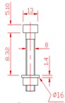
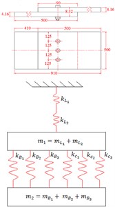
The problem geometry consists of two flat composite plates, positioned in the shape of lap, with number of bolts varying from 1 to 3, Fig. 2(a)-2(c), and frequency analysis of structure is performed when it is subjected to shock load, Fig. 1(b). An analytical dynamic model is developed using spring based approach to determine the effect of an increase in number of bolts on stiffness and frequency characteristics. The material under consideration is carbon-fiber/epoxy, designated as HTA/6376 [5]. The length of each plate is 500 mm and the region of overlap is 90 mm to give 910 mm as the overall length of this geometry. The region of overlap is secured in position with the help of titanium M8 bolts, Fig. 1(a), inserted equidistantly in 500 mm width of plate. The composite laminates have a quasi-isotropic layup with sequence of stacking as [45/0/–45/90]4s. Each layer has a ply thickness of 0.13 mm that led to total thickness of 4.16 mm for each composite plate. The geometry is completely fixed from the left and right end. The homogenized lamina material properties and aerospace grade titanium alloy bolt material properties are obtained from McCarthy [12] and is referred here in Table 1. The frequency response obtained from the analytical model are only validated with 3D FE simulations since no experimental frequency results are available for this type of joint configuration with shock load as forcing function.
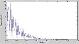
Fig. 1a) Bolt specifications, b) forcing function plot
a)
b)
Table 1Material properties [12]
Homogenized laminate properties | |||||||
54.25a | 12.59 | 4.55 | |||||
54.25a | 20.72a | 4.55 | |||||
0.309a | 0.332 | 0.332 | |||||
Titanium properties | 110 | 0.29 | |||||
aValues verified from classical laminate theory All units in GPa except that is unitless entity | |||||||
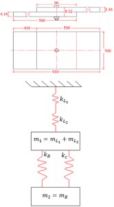
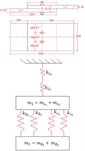
In order to evaluate the model’s accuracy in terms of predicting frequency response of multi-bolt composite joints; 1, 2 and 3-bolts single lap joint assemblies are modeled and investigated. Several researchers have used spring-mass system for analyzing the composite bolted lap structures [4-5]. An effort has been made in this study to analyze the shock loading behavior of these geometries. The bolted single lap geometries are transformed into a system of springs and masses Fig. 2. This methodology is applicable to any type of bolted lap geometries. The shock load is applied in the lateral direction to the top surface of the plate. This 2-DoF spring mass system consists of stiffness of bolt kB, stiffness of clamped region , stiffness of laminates and , mass of composite laminate plates and mass of bolt(s) and the geometrical parameters. Analysis of spring mass system is based on the assumptions that; (1) The masses can move freely only in lateral direction; (2) The springs possess stiffness only in lateral direction.
Gray and McCarthy [5] ignored the mass effects in their analysis, however, the current investigation incorporates both the mass of laminates and the bolts with system subjected to shock load applied in lateral direction.
Fig. 2Bolted lap geometries and corresponding mass-spring systems
a)
b)
c)
Each mass in the system is inspected with the help of free-body diagrams. The equations of motion Eq. (1) and the corresponding system of linear equations for this mass – spring model subjected to shock load may be written in matrix form as Eq. (2):
where; and are the displacements of mass 1 and 2 respectively, – mass of laminate 1 and 2, – mass of bolt, – stiffness of laminate 1 and 2 and – added stiffness of bolt () and clamped region ().
The stiffness of different parts and regions of mass-spring system are obtained as follows.
Stiffness of bolt: According to Gray and McCarthy [5] bolt stiffness can be represented by:
where, – Young’s modulus of bolt material, – cross-sectional area of bolt shank and – length of bolt shank
Stiffness of clamped region: It is dependent on ratio, i.e. if 6 then it is given by Eq. (4) [5, 13], otherwise it will be calculated from Eq. (5):
where; – length of plate, – bolt shank diameter, – thickness of laminate, – Washer/Bolt shank diameter , – Young’s modulus of material; For composite materials may be replaced by , – Length/Bolt diameter and – Pressure distribution angle = 36°.
Stiffness of Laminate: The stiffness of laminate defined in [4] is modified by using the homogenized laminate modulus in global -direction, and leads to following form:
where; – stiffness of laminate, – homogenized laminate modulus in global -direction, – width of laminate, - thickness of laminate, – pitch of bolt, – diameter of bolt.
3. Frequency response of bolted lap geometry under shock load
Current investigation is intended to determine the stability of structure by analyzing its frequency response results. So, the shock load for 0, is applied on the surface of plate. is the peak load and is the initial time and in this case it is 0.1 sec.
The displacement, and , response of bolted composite lap structure to the applied shock load is assumed as:
Substituting displacement responses from Eq. (7) into Eq. (1) we get:
Eq. (8) and Eq. (9) can be represented in matrix form as:
For nontrivial solution to obtain frequency response of system, the determinant of coefficient of and must be zero, we get:
Eq. (11) is known as the frequency or characteristic equation of the composite bolted lap structure. The values of model parameters i.e. mass and stiffness coefficients for three bolt plate assemblies (1, 2 and 3 bolts) and corresponding fundamental frequencies are stated in Table 2.
Table 2Model parameters and fundamental frequencies of different bolt plate assemblies
Parameters | (kg) | (kg) | (N/m) | (N/m) | (N/m) | Frequency (rad/s) / (Hz) |
1 Bolt | 3.327 | 0.00845 | 1.99E08 | 1.69E09 | 3.47E09 | 996.739 / 158.716 |
2 Bolts | 3.326664 | 0.0169 | 3.98E08 | 1.69E09 | 7.34E09 | 995.701 / 158.55 |
3 Bolts | 3.325996 | 0.02535 | 5.97E08 | 1.69E09 | 1.04E10 | 994.659 / 158.385 |
4. FE Simulations of bolted lap geometries using ANSYS
In order to validate the proposed approximate analytical model, 3D finite element single, double and triple bolted lap geometries are modeled in ANSYS. The composite plates have a quasi-isotropic lay-up i.e. [45/0/–45/90]4s, bolted with aerospace grade titanium bolts. The translational and rotational degrees of freedom (DoF) of all nodes at both ends of lap geometry are completely constrained. Homogenized laminate material properties, Table 1, are used for modeling of composite laminates. The forcing function i.e. the shock load is applied by keeping in account the transient loading that is applied to the top surface of whole geometry for duration of 1 s. The initial time at which the shock wave strikes the target is 0.1 seconds. The fundamental frequencies acquired from FE simulations are shown in Fig. 3(a)-3(c). Comparison of results Fig. 3(d) shows a good agreement between both analysis methods. The maximum frequency is acquired with geometry having least number of bolts and regions of stress concentration.
Fig. 3Fundamental frequencies using FEA simulations
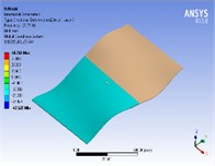
a) 1-bolt
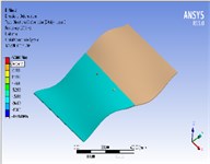
b) 2- bolts
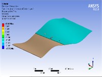
c) 3-bolts
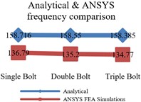
d) Comparison
5. Discussion on results
In this work an attempt has been made to investigate and correlate physical changes in composite bolted structure to changes in stiffness and frequency characteristics. Results obtained from both analysis methods reveal that the frequency response obtained after application of shock loading is sensitive to increasing number of bolts and bolt holes that leads to decrease in frequency. No, doubt the bolts are inserted in bolt holes but the regions of stress concentration generated around each hole reduce stiffness and frequency. Therefore, the lowest frequency response is attained for geometry having 3 bolts i.e. 158.385 Hz and 134.77 Hz for analytical and ANSYS FEA results respectively. The highest frequency response is acquired for single bolt geometry i.e. 158.716 Hz / 136.79 Hz. The main contributing factors to cause decrease in stiffness and frequency are increase in the number of bolts and the corresponding bolt holes. The average error between analytical and ANSYS FEA results is almost 10 %. The main factors contributing to this discrepancy are; (a) The difference of solution technique, solver type and working environment. In FEA results following factors contribute to the solution i.e. meshing quality, numerical techniques used by selected solver in FEA software and element type etc. (b) In current analysis, ANSYS FEA used Newton’s Raphson method to converge solution while in analytical modeling characteristic equation, containing stiffness of different regions of bolted geometry, is developed to obtain frequency. FEA solver used the direct method to acquire frequency response and the analytical response acquired through characteristic equation gives approximate results. (c) An adhesive bond is used in the region of overlap in ANSYS FEA analysis while stiffness of adhesive is ignored in analytical modeling (d) In analytical modeling homogenized laminate modulus existing in the direction of load application i.e. -direction is considered in the formulation for stiffness of laminate while in ANSYS FEA the composite plates are completely modeled by defining orientation of fibers in each layer.
6. Conclusions and future scope
An approximate analytical model and 3D FEA are presented to determine the effect of existence of bolts, an increase in number of bolts and application of shock loading on vibration characteristics and stiffness of composite laminates. The problem geometry consisted of two overlapping flat bolted composite plates. The frequency analysis of the test specimen is performed when it is subjected to shock load. An analytical model of defined configuration is approximated by mass-spring system having the effects of stiffness of clamped region, bolt and composite laminates. The analytical frequency responses of bolted composite geometry are compared with ANSYS FE simulations to check the validity of the developed analytical model. It is concluded that decrease in stiffness leads to decrease in frequency of system i.e. frequency response can be considered as a means of detecting changes in structural stiffness. The main contributing factors to reduce system performance are increase in region of stress concentration and number of bolts. Efforts are underway to use spring based approach to assess the frequency response of cracked composite plates to address a more realistic problem in aerospace industry.
References
-
Tate M. B. Preliminary Investigation of the Loads Carried by Individual Bolts in Bolted Joints. NACA Technical Note No. 1051, Washington, NACA, 1946.
-
Nelson W. D., Bunin B. L., Hart-Smith L. J. Critical Joints in Large Composite Aircraft Structure. DTIC Document, 1983.
-
McCarthy M., McCarthy C., Padhi G. A simple method for determining the effects of bolt-hole clearance on load distribution in single-column multi-bolt composite joints. Composite Structures, Vol. 73, Issue 1, 2006, p. 78-87.
-
McCarthy C. T., Gray P. J. An analytical model for the prediction of load distribution in highly torqued multi-bolt composite joints. Composite Structures, Vol. 93, Issue 2, 2011, p. 287-298.
-
Gray P. J., Mccarthy C. T. An analytical model for the prediction of through-thickness stiffness in tension-loaded composite bolted joints. Composite Structures, Vol. 94, Issue 8, 2012, p. 2450-2459.
-
Barrois W. Stresses and displacements due to load transfer by fasteners in structural assemblies. Engineering Fracture Mechanics, Vol. 10, Issue 1, 1978, p. 115-176.
-
Gray P., McCarthy C. A highly efficient user-defined finite element for load distribution analysis of large-scale bolted composite structures. Composites Science and Technology, Vol. 71, Issue 12, 2011, p. 1517-1527.
-
Soykasap Ö., Mecitoğlu Z., Borat O. Dynamic response of composite cylindrical shells to shock loading. Mathematical and Computational Applications, Vol. 1, 1996, p. 85-96.
-
Upadhyay A., Pandey R., Shukla K. Nonlinear dynamic response of laminated composite plates subjected to pulse loading. Communications in Nonlinear Science and Numerical Simulation, Vol. 16, Issue 11, 2011, p. 4530-4544.
-
Vaziri A., Xue Z., Hutchinson J. W. Performance and failure of metal sandwich plates subjected to shock loading. Journal of Mechanics of Materials and Structures, Vol. 2, Issue 10, 2007, p. 1947-1963.
-
Nemes J., Randles P. Modelling the Response of Thick Composite Materials Due to Axisymmetric Shock Loading. DTIC Document, 1991.
-
McCarthy M. Three-dimensional finite element analysis of single-bolt, single-lap composite bolted joints. Part I: Model development and validation. Composite Structures, Vol. 71, Issue 2, 2005, p. 140-158.
-
Nassar S. A., Abboud A. An improved stiffness model for bolted joints. Journal of Mechanical Design, Vol. 131, Issue 12, 2009, p. 121001.
About this article
