Abstract
The article describes the processes for application of wear-resistant flame-sprayed coatings to the machine parts. It considers industrial prototype tools, both domestic and foreign. The field of application of high velocity high-temperature sprays is expanded by using them for removal of insulation coatings from oil and gas pipes and by including solid particles (abrasion agents or water) to produce a resilient steam/gas jets for cleaning the pipe surface.
1. Introduction
The key task in the modern development of machinery is to improve durability and reliability of assemblies and machine parts in metallurgical, chemical, oil and gas, mining, airspace, etc. industries by reducing the intensity of wear-and-tear and corrosion and by applying the thermal spraying.
The most advanced techniques for application of gas-sprayed coatings include plasma and high velocity gas flame processes [1-3].
Small-sized rocket guns with high energy capacity were first used at the ore-mining and processing enterprises in the USA and the Soviet Union. With high temperature and speed of the gas flow, they proved to be highly efficient in rock breaking, well drilling, surface treatment of granite chunks and mining the slot cuts when mining for the granite chunks.
The flow pattern in the high velocity sprays and their parameters depend on the nozzle shape, the sort of spray medium and ambient variables. According to the listed factors, it is a regular practice to group the sprays into a number of types. Based on the spray medium, distinction is made among one-phase, two-phase and three-phase sprays. Based on the nozzle shape, distinction is made among flat, axially-symmetrical and 3D sprays. Based on the stagnation enthalpy or on the structure of stagnation enthalpy or the structure of internal spray, distinction is made among low-temperature (internal energy of molecules practically consists from the energy of translational and rotational degrees of freedom), high-temperature (vibrational degrees of freedom are excited) and plasma (contribution of ionization energy is significant) sprays.
Based on the off-design () which is equal to ratio of the nozzle cross-section pressure to the ambient pressure, there are design (1), underexpanded (1) and overexpanded (1) sprays. Depending on the direction of the ambient motion against the nozzle, distinction is made between sprays injected into the submerged space; concurrent, counter and cross flows. Based on the tenuity, distinction is made between dense sprays and low-density gas sprays. Finally, stationary and non-stationary sprays are distinguished [4].
A high velocity spray is a non-stationary, spatially non-homogenous unstable gas formation. The gaseous environment resists the spray flow and the flow flexes warps and fluctuates. Impact and shock waves observed in the initial gas-dynamic area of high velocity spray interact with each other and the spray boundaries. When the impact waves interact in the spray itself, closed subsonic areas are formed in the flows [5].
2. Materials and methods
The last decade has witnessed a rapid progress of high velocity techniques of application of powered coatings under a common English term HVOF (High Velocity Oxy-Fuel) the Russian counterpart of which is the HVGF (High Velocity Gas Flame). The sprayed materials – polymers, carbides and metals – form high quality thermal-, wear- and corrosion-resistant coatings which can sustain the effects of impact and chemically-active media and high thermal loads.
Alternatives are gas dynamic cold spraying (GDCS), detonation gun (D-gun) and plasma spraying (PS) and supersonic quenching [6].
Table 1 shows that Intelli-Jet is the most advanced installation. It does not require oxygen as the oxidizing agent or water cooling [7, 8].
According to the review of manufacturers’ data [9, 10] (Table 2), Intelli-Jet provides the highest velocity of particles and the maximum temperatures of these particles which are part of alloy matrix is by 100 degrees lower than the cobalt melting point. This features that make them different from other installations lead to reduction in oxidation of particles and allow for improvement in the spraying rate. Feedstock cost-effectiveness for Intelli-Jet means reducing 1.6...2.5 times the relative cost of coatings.
Table 1Hourly consumption of materials of some sonic gas flame installations
Intelli-Jet | JP -5000 | DJ2700 | Top Gun | ||
Oxygen, m3 | – | 60 | 18 | 21 | |
Compressed air, m3 | 300 | – | 23 | – | |
Fuel | Type | Propylene | Kerosene | Propylene | Propylene |
Consumption, kg | 30 | 21 | 17 | 16 | |
Nitrogen, m3 | 0.96 | 1.2 | 1.08 | 1.02 | |
Cooling water, m3 | – | 1 | 0.72 | 0.72 | |
Table 2HVGF unit output parameters WG-10Cо-Cr Sprayed material, (–45+10) mcm fractions
Intelli-Jet | JP -5000 | DJ2700 | Top Gun | |
Average velocity of particles, m/s | 775 | 665 | 570 | 420 |
Maximum temperatures of particles, K | 1543 | 2078 | 2253 | 2573 |
Spraying rate, kg/h | 26 | 12 | 9 | 2,1 |
Sprayed material utilization ratio, % | 68 | 40 | 64 | 60 |
Spraying relative cost | 1 | 2.5 | 1.6 | 1.7 |
The structure and mechanical properties of the coating depend on the temperature and the velocity of sprayed particles at the moment of their contact with the backing [11].
Supersonic spraying technique is based on continuous combustion of ignitable gas in the oxygen, while forming a supersonic spray on the gun outlet. Powdered material is introduced into the flow; it is heated up and directed at a high speed to the treated part.
The process equipment for high-velocity gas flame spraying includes a high velocity gun, a container for injected powder, control, an ignitable gas bottle and an oxygen bottle.
Coatings formed by high velocity gas flame spraying have strong adhesion, low porosity and significantly increase the service life of equipment operated in the contact with aggressive media or affected by intensive wear. They have the same or even better characteristics as the coatings sprayed with plasma tools but they are 1.5-2 less expensive.
According to GOST 28076-89, thermal spraying is grouped as follows: gas flame spray, plasma spray, plasma arc spray, high-frequency plasma spray, electric arc spray, detonation spray, controlled environment plasma spraying, dynamic vacuum plasma spraying (DVS) and melt spraying. The said GOST does not describe the supersonic spraying which has been dynamically developed for the last 10-15 years in industrially-developed countries by Cabot Corporation, Browning Engineering, Thermodyne Corporation, Perkin-Elmer Corporation (USA), UTP Schweissmaterial GmbH (Germany) and others [12].
The world’s best practice of producing gas thermal coatings at supersonic velocities of the particles is called the ‘High Velocity-Oxygen-Fuel or HVOF for short.
The Russian research institute for structural materials and processes (the Moscow State Technical University after N.E. Bauman) has developed the equipment for supersonic gas-flame spraying of wear- and corrosion-resistant coatings, reinforcement, repair and refurbishment of worn parts. A supersonic gas spray generated with special gun is used for spraying the coatings [13].
The working process in gun is similar to that in the microthruster. Due to small dimensions, the equipment can be used in field. The cost of the equipment is around ten times lower than that of foreign stationary installations. The characteristics of the coatings comply with those achieved by the best state-of-the-art plasma equipment at a lesser cost (by 1.5-2 times). The quality of the coatings is 2-3 times higher than that of standard flame-spraying. Propane/Methane is the fuel agent and oxygen is the oxidizing agent. The velocity of the supersonic spray reaches 2,600 m/s, temperature is around 2,200 to 2,700 °С. The porosity of coatings does not exceed 5 % and their thickness is 0.1-5 mm. 3.5 kg gun is cooled down with running water; the ignition system is piezoelectric one.
The velocity of heated gas spray on the gun nozzle cross-section reaches 1,700 to 2,700 m/s, which allows obtaining coatings with the adhesion strength of around 100 МPа and coating porosity of 0.5 %, which, in their characteristics, is close to coatings produced by detonation spraying. With the thickness of supersonic thermal coating up to 0.3 mm, there is little porosity (according to the data provided by a spraying laboratory of scientific production organisation Tularchermet) [14].
Alloys based on nickel, iron and cobalt, as well as metal carbide and self-fluxing alloys; nitrides of silicone, aluminium, chromium, boron, etc. are used as powdered materials in the supersonic thermal spraying.
Use of gun implies that there is just an additional air compressor. With a mechanism of wire fed from the semi-automatic welding machine, spraying is possible with 1.5-2.5 mm-diameter powdered wires, which is far less expensive than the use of powdered materials.
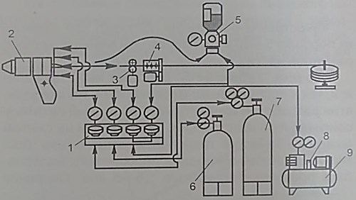
Fig. 1 [14] shows the layout of the unit for supersonic gas-flame spraying of coatings from powdered materials and wire.
Fig. 1Diagram of the supersonic gas-flame spraying of coatings from powdered materials and Теrmika-HS wire: 1 – plasma-forming gas feed control block, 2 – supersonic gun; 3 – wire feeder, 4 – wire feeder control, 5 – powder feeder, 6, 7 – ignitable gas and oxygen correspondingly, 8 – air feed compressor, 9 – receiver
The scientists from Kazakh National Technical University named after K. I. Satpayev tested the gas-flame destruction of insulation coatings on oil and gas pipes jointly with Intergas Central Asia JSC. They developed a new design of the rocket gun, into which water is injected to form gas/steam mixture, as well as solids (grits or sand), to increase the mechanical part of the spray [16].
Two-phase flow with a high velocity of solid particles will allow increasing the speed at which the coating is destructed and further cleaning of the pipe surface for application of a new coating.
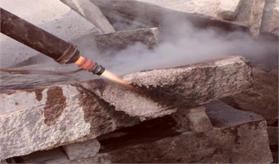
The reached rate of the flame cleaning is 10 m2/h at the fuel consumption consumption rate, the fuel consumption rate is 7-8 kg/h, the air consumption rate is 3.5 m3/min. Fig. 2 presents the moment when the pipe is cleaned with a thermal hand tool.
Wide opportunities are offered by using high temperature and high velocity gas sprays (gas-dynamic metal-spraying gun) for application of thermal coatings, namely: the strength of adhesion of coating and the surface is increased and the process gets cheaper as compared to the existing plasma and detonation spraying.
There is some experience in creating a pilot installation for cleaning the gas pipelines that was designed by VNIIGaz (Russia) jointly with Van Voskalen company (Netherlands) which proved the viability of using supersonic thermal spray technologies in removing the insulation with simultaneous preparation of the surface for application of new coating during the repair of gas pipelines of a bigger diameter [17].
Metallurgical waste slag, sand, cast-iron breakage with up to 2 mm fraction size as abrasive agents; compressed air, liquid fuel, compressed methane or liquefied propane is used as fuel component.
The authors [18] have designed a unit for application of thermal coatings applied with supersonic high-temperature gun.
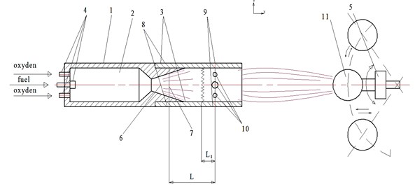
The general view of the proposed unit for application of thermal coatings is schematically represented in Fig. 3.
Fig. 2Treatment of the pipe with a thermal hand-tool
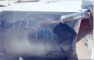
Fig. 3Unit for application of gas thermal coatings: 1 – combustion chamber, 2 – gas-jet gun, 3 – cylindrical top, 4 – three-channel adjuster, 5 – treated parts handler, 6 – gas-flame gun nozzle, 7 – lengthwise relative cross-section L, 8, 9 – holes, 10 – ring diffuser, 11 – workpiece
Also, they have offered a gas-flame spraying of metal powders allowing for increase in strength of adhesion of the spray to the base [19].
Fig. 4 shows the described gas-flame spraying of metal powders 4.
Also, the pipes surface cleaning method and unit were designed to increase efficiency and to expand technological capabilities of cleaning the pipes off the insulation cover [20].
Pipe surface cleaning includes formation of a resilient gas spray and delivering the kinetic energy thereto. This energy is sufficient for destruction of strong materials. Cleaning is carried out consistently, i.e. initially, by using a resilient steam/gas spray that is formed by adding a certain amount of water to a high-speed, high-temperature gas spray. The volume of water determined based on the temperature of the minimum adhesion of the covering to the pipe surface. Then further cleaning and processing are continued with another gas spray formed by injecting an abrasive mix into the resilient jet.
Fig. 5 shows a sand-blasting unit for cleaning the pipe surface.
Fig. 6 shows a fragment of creation of torch steam/gas jets used for cleaning of a surface of gas pipes and in processing and cutting the granite rocks.
Fig. 4Schematic diagram of the unit for metal application of flame-sprayed metal powders: 1 – combustion chamber, 2 – heating/burning zone in the combustion chamber, 3 – main spray from the combustion chamber, 4 – feed of sprayed powder, 5 – feed (ejection) of oxidant (the ambient air), 6 – external spray, 7 – the set length of active zone of the main spray, 8 – the set length of the shock-wave formation, 9 – shock wave front (compression wave), 10 – spraying flow, 11 – base for coating formation
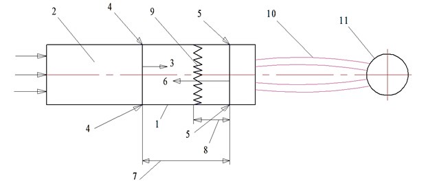
Fig. 5Sand-blasting unit for cleaning of pipe surfaces: 1 – combustion chamber, 2 – internal contour, 3 – central supersonic nozzle, 4 – external contour, 5 – external nozzle, 6 – extension piece, 7, 10 – the set length, 8 – discharging zone, 9 – section, 11, 12 – channels, 13 – resilient gas/steam spray, 14 – another gas spray, 15 – coating on the treated pipe
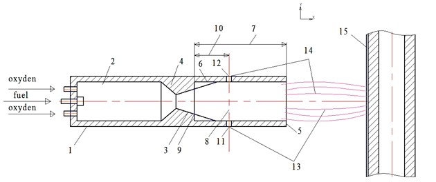
Fig. 6A fragment of introduction into the torch flame to form steam/gas mixture
3. Conclusions
A review has been made on application high-velocity and high- temperature gas jets used in various technological processes (high-velocity flame spraying), i.e. a process of thermally-sprayed strengthening coatings applied to the surface of machine parts and further development of this process for destruction of insulating covers of oil and gas pipes and preparation of a surface for application of new coating.
The conducted experiments showed the expediency and cost-efficiency in rock destruction.
References
-
Kalita V. I., Baldayev L. H., Lupanov V. D., Shatov A. P. Modern thermal spraying equipment and coatings. Svarschik – Professional, Vol. 3, 2005, p. 14-15.
-
Baldayev L. H. Renovation and Reinforcement of Machine Parts by Thermal Spraying KHT. 2004, p. 134.
-
KorobovYu. S. Prolongation of parts service life by supersonic flame spraying. Heavy Mechanical Engineering, Vol. 7, 2006, p. 34-38.
-
Dulov V. G. Supersonic Gas Jets. Novosibirsk, 1983, p. 202.
-
Isaeva L. A. Application of supersonic currents in technological process of hardening. A Compilation of Works of 13th Workshop on Jet, Detachable and Non-Stationary Flows Devoted to Fundamental and Applied Issues of Mechanics of Continuous Environments. Tomsk, 2012, p. 169-172.
-
Korobov Yu. S. Comparative analysis of supersonic gas-flame techniques for application of coatings. Gas Turbine Technologies, Vol. 6, 2005, p. 38-40.
-
Kharlamov Yu. A. Thermal spraying of coatings and environmental friendliness of manufacture, operation and repair of machines. Heavy Mechanical Engineering, Vol. 2, 2000, p. 10-13.
-
Nestler M. C., Erning U. Characteristics and advanced industrial applications using the “Diamond Jet Hybrid” – the third generation of HVOF systems. Films and Coatings, St. Petersburg, Vol. 5, 1998, p. 195-202.
-
Verstak A., Baranovski V. Activated combustion HVAF coatings for protection against wear and high temperature corrosion. Proceedings of the ITSC, Thermal Spray 2003: Advancing the Science and Applying the Technology, ASM Publication, Vol. 1, 2003, p. 58-63.
-
Kreye H. A comparison of HVOF systems-behavior of materials and coating properties. 4th HVOF Colloquium, Erding, Munchen-Bavaria, 13 21 P.
-
Baldayev L. H., Shesterkin N. G., Lupanov V. A., Shatov A. P. Features of high velocity flame-spraying. Welding Production. Vol. 5, 2003, p. 43-46.
-
Khromov V. N., Vertsov V. G., Korovin A. Ya., et al. From subsonic to a supersonic flame-sprayed coverings in refurbishment and hardening of machine parts. Welding Production, Vol. 2, 2001, p. 39-48.
-
New Technologies and Equipment at the Intertool-98 Exhibition. Tractors and Farm Machinery. Vol. 2, 1995, p. 48.
-
Korovin A. Ya, Abashev N. G., Khromov V. N. Experience of the municipal enterprise Orelelektrotrans in parts refurbishment with flame-sprayed coverings. Conference on State and Prospects of Refurbishment, Hardening and Manufacture of Machine Parts, 1999, p. 74-77.
-
Korobov Yu S. Rational approach to refurbishment of equipment parts by thermal spraying. EkzpozitsiyaMashMetSvarka, Vol. 1, 2012, p. 13-17.
-
Klimov P. V., Baishuakov A. A., Povetkin V. V. New technical solutions for repair of trunk pipelines. Oil and Gas, Scientific and Technical Journal, Аlmaty, 2006, p. 89-95.
-
Veyulin I. I., Gusev V. А., Spirin V. А., Povarov О. V. Supersonic thermal spray technologies for gas pipeline cleaning. Gas Industry, Vol. 4, 2003, p. 60-62.
-
Baishuakov A. A., Povetkin V. V., Povetkin A. V. Unit for application of thermal-sprayed coatings. Preliminary Patent No. 15419-2004, Request No. 2003/730.1, 2003.
-
Baishuakov A. A., Klimov P. V., Povetkin V. V. Flame Spraying of Metal Powders. Preliminary Patent No. 15177-2004, Request No. 2003/0581.1, 2003.
-
Baishuakov A. A., Povetkin V. V., Klimov P. V. Pipe Cleaning Technique and Unit. Preliminary Patent No. 14999-2004, Request No. 2003/0627.1, 2003.
About this article
