Abstract
The article provides an analysis of use of heavy-duty gear trains in the mining industry. It was revealed that it is necessary to create a dynamic model to calculate the acting stresses and durability in order to assess the dynamic parameters of the gear train. The article provides the results of use of Nastran software shell in terms of stress-strain behavior of the girth gear.
1. Introduction
Ore-mining and concentrator plants in Kazakhstan process a huge volume of ore containing valuable minerals. Ball and rod mills are used to grind and process them further. Ball mills are heavy-duty machines. The grinding process and the accepted ball motion flow inside the mill have an impact character. Drive gears are affected by impacts, which cause wear and tear on gear teeth and reduces operational life of gear trains and mills as a whole. It is a very crucial task to study parameters of resistance to wear-and-tear of teeth engagement on heavy-duty gear trains with regard to dynamic loads.
When designing heavy-duty gear trains, it is necessary to assess force parameters of tooth engagement, to select rational values and to develop dynamic model for calculation of existing stresses and durability.
The method of calculation of the ring gear drive ball mill designed in Nastran environment, taking into account the stress - strain state of the crown, to perform evaluation of the durability of the structure. The methodology takes into account the fatigue properties of structural materials, describes the fatigue curve, which represents dependence of the number of cycles to failure the standard sample to the level of stress amplitude cycles. Through established finite element model of the ring gear calculation of durability of the ring gear is made, taking into account the features of the load circuit.
2. Materials and methods
Open gear trains on ore-grinding mills differ considerably from gear trains characteristic of general machine building. They are unique in their sizes. Girth gears on big mills are made from several parts and site-assembled at mining concentrator plants. The pinion of the girth gear is the shell, the fabrication and installation of which does not ensure geometrical and true axis of rotation. Finally, the open gear train is a variable-speed gear. This leads to a considerably uneven distribution of load across the width of the girth gear.
Thus, concentration of load on open gear trains in ore-grinding mills can be calculated by using a formula by A. I. Petrusevich, while neglecting flexural strain and torsion of gear wheels and taking the maximum load in the cross-section which is 1.25 distant from the tooth face [1]. The tooth width module ratio for ore-grinding mills is equal to 0.025-0.036. Therefore, it could be assumed that the highest specific load is affected in the cross-section of the tooth which is 0.04b distant from the butt end [2]. Then the formula of A. I. Petrusevich should be presented as follows:
where is the load concentration coefficient; is the effective width of gear wheels; is the average teeth-length total deformation of mating teeth pair; is the total azimuth angle of gear teeth and wheel.
Eq. (1) is true for the case of full contact of the mating teeth pair when the load concentration coefficient is equal to 1.92.
It is commonly assumed that the teeth in open gears are aged completely due to wear-and-tear and the concentration coefficient is reduced to 1. However, complete setting-in is possible only when . Gear end face wobbling cause variance in the teeth azimuth angle.
The electric drive on the ball mill is a very complex system that considers all inside acting forces. The main task, therefore, is to assess main determining factors on the basis of which electromechanical diagram is designed to consider main inertial elements, linkages and forces [3, 4].
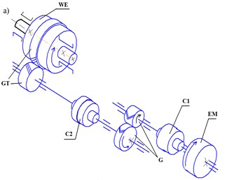
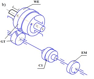
When studying the dynamic processes, the motor torque can be considered to be a constant or independent time variable. In this event, electromechanical diagram is designed to determine main inertial elements and linkages in the mechanical part of the drive. Fig. 1 shows exemplary kinematic diagrams of the mills, the drives of which have some differences [5, 6].
Mill functioning is affected by elasticity forces, inertia forces of unbalanced shell, dissipating forces that are friction forces in the shell and the drive pinion supports, in teeth engagement and couplings and in the gear pinions when twisted.
In general, kinematic chains of ball mill drive mechanisms have clearances conditioned by deficiencies in workmanship and wear-and-tear on the gear elements which are distributed mainly among couplings and teeth engagement.
Fig. 1Ball mill shell rotating mechanisms: а) Grate-discharge ball mills 2100×2200; b) central discharge ball mills 2800×4400. EM – electromotor, C1, C2 – couplings, G – gearbox, GT – gear train, WE – working element
Each part of the drive has its sizes and weight. If we take into account all real structural peculiarities, the design diagram of the unit should be considered as a multi-weighted mechanical system with resilient linkages and clearances. The movement and dynamic study of such a system is a complex and intractable task [6, 7].
However, if we keep in mind that main regularities of motion of such systems are determined by the biggest weight, clearances and the lowest rigidity (elasticity), it allows narrowing the model of the whole unit to three-, two- or single-mass dynamic systems with the reduced masses and moments of inertia equal to elastic linkages and total clearance (or without it) reduced: 1) to the drive motor if the task is to study its rotation and loading; 2) to the operating section of the unit if its rotation and behaviour needs to be studied.
The calculation methodology for a girth gear on the ball mill drive was developed in the Nastran environment in the following sequence: 1) making up a model in line with the corresponding test loading mode. Purpose of loading modes; 2) purpose of fatigue characteristics of structural materials; 3) building a final elemental model of the designed structure, boundary conditions corresponding to installation of the gear wheel in the test gearing, as well as the model of external load; 4) stress-strain analysis of the model within the scope necessary for estimation of durability of this structure using MSC/Fatigue software; 5) calculation of girth gear durability using MSC/Fatigue module and review of capabilities of this module.
With no experimental data, two methods were used to obtain the baseline data with the help of MSC/Fatigue hard-coded material generator:
– for fatigue characteristics of the material by its type and main;
– for characteristics like elasticity module and ultimate tensile strength.
Considering the peculiarities of the analysed structure, the loading pattern shown in Fig. 2 was accepted as the design mode.
Fig. 2Loading pattern
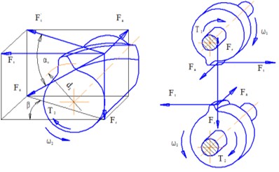
Below are the data on forces acting in the gear and pinion engagement: 1) circumferential force: 5362315 H; 2) radial force in tooth engagement: 195972 H; 3) axial force: 49333 H.
Practical ways of obtaining the material or part fatigue characteristics are necessary for calculation of durability:
1) Plotting a test curve of the part fatigue resistance. To do that, a set of (20-30 pcs.) similar gears should be tested for bend with rotation at different levels of load and plot the dependency of the number of cycles to failure to the level of load. This method allows the highest accuracy of durability estimate but it is very cost-intensive and time-consuming.
2) Using fatigue curves of material used in the girth gear that were in accordance with the established standards for fatigue testing methods.
3) Using statistics of the completed tests on girth gears [8]. A design model is built for determining the stress-strain behaviour during the tests for wheels with the known number of cycles to failure under the set load conditions. The level of tensions which led to the girth gear failure within the known number of loading cycles is determined by calculation. The obtained result shall apply to newly-developed analogue products made of this material following the same technique.
4) Calculation of necessary material fatigue resistance characteristics on the basis of the static load strength known for this type of material. It is recommended to set standard requirements for these methods.
MSC/Fatigue software allows obtaining baseline data on material characteristics necessary for calculation of durability by using hard-cored generator of material fatigue characteristics. In doing that, use is made of the software developers’ experience in characteristics of foreign structural materials.
To set the necessary characteristics of the material, its type is selected from Table 3-1 – Material Type Numbers and Descriptions in PFMAT Material Listing Section of 2005 MSC/Fatigue Manual.User’s Guide Volume I and the most common characteristics are elasticity module () and ultimate tensile strength (). Using empirical relationships of static and fatigue properties of foreign materials, we will obtain material characteristics for all types of durability calculations supported by MSC/Fatigue software.
The problem used fatigue resistance characteristics obtained by using the MSC/Fatigue hard-cored generator of material fatigue characteristics, as well as standard characteristics of girth gear materials.
The girth gear has the following characteristics: 1) the wheel is founded, wheel material is 35CrMoA steel; 2) ultimate tensile strength is equal to 600 MPa; 3) elasticity modulus if 2.1∙105 МPa.
In line with the standard requirements, the material fatigue resistance is described by the S-N curve that represents the relationship between the number of cycles () to failure of the standard sample to the level of stress cycle amplitudes () in the design cross-section of this sample.
Representation of S-N curve: , where is the number of cycles to failure of the sample; is the amplitude of the stress cycles; is the restricted durability limit of the material of the structure on the basis of loading cycles; is the slope index of S-N curve approximated by exponential equation; – the number of stress cycles.
In logarithmic coordinates, the S-N curve has two straight sections with different slope angle against axis:
– with , the slope index () for smooth standard samples without experimental data should be calculated by using the following formula:
– with the S-N curve is parallel to axis.
With no experimental data, the limit of restricted durability of steels of this type may be determined on the basis of 107 cycles using the following formula:
where is ultimate tensile strength.
MSC/Fatigue software is completed with the description of material fatigue resistance characteristics in the form of S-N curve which represents a relationship between the number of cycles to failure of a standard N sample to the level of throw of stress cycles in the design cross-section of this sample S1.
The plot of S-N curve is determined: , where is a section cut on the throw axis at the cycle 0 point; are values of slopes of two sections on the S-N curve.
The probability of reaching the ultimate limit state is set using the logarithm of number of cycles to failure which determines the degree of fatigue characteristics dispersion. To obtain reliable results of durability calculation, this characteristic should be obtained by summarizing experimental data on characteristics of materials used in a specific production considering dispersion of properties within one batch of blanks and between different batches.
MSC/Fatigue , and software allows obtaining a general dissipation characteristic depending on the material type, elasticity module and ultimate tensile strength. 35CrMoA Steel properties are given in Table 1.
Fig. 3 shows the 35CrMoA Steel S-N Curve plotted using the Graphic display option in the main MSC/Fatigue module window.
3D Model (Fig. 4) was created in the COMPAS CAD Shaft module on the basis of geometrical parameters.
In creation of analytical model, a fragment of the wheel was cut out in order to save machine capabilities as stresses will be localized across the gear tooth area.
The model built in the Russian CAD system was successfully imported with the help of CAE exchange files into the Nastran system. Break-down to final elements are modeled as test-type solid elements.
The analytical model for determination of acting stresses is given in Fig. 5. The requirements for the type of elements and the grid quality must be increased because local stresses should be calculated with regard to their concentration to assess the fatigue limit.
Table 135CrMoA Steel properties in standards terms.
Material | ,МPa | , MPa | ,МPа | ||
Steel 35CrMoA | 600 | 2.1*105 | 315 | 9.6 | 107 |
Fig. 335CrMoA Steel material S-N curve (NASTRAN program window)
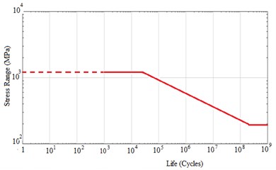
Fig. 43D Model of gear and pinion assembly
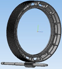
Fig. 5Generated grid
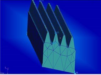
Fig. 6Distribution of equivalent stresses in the girth gear
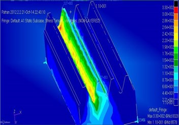
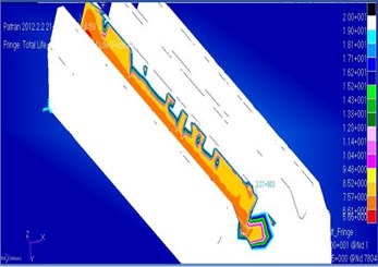
Fig. 7The logarithm of durability
The index of S-N curve of 35CrMoA steel is 7.5…9.6.
Mechanical analytical model includes rigid fixation intending application of bracings on six levels of freedom and loading in the form of resultant distributed load on the tooth flank.
The static problem was solved to determine the stress-strain behavior of the girth gear using the MSC/Nastran software (Fig. 6).
According to the resultant diagram, the maximum stress has the value of 330 MPa, allowable stress is 600 МPа, static strength coefficient: 1,72.
Stress results show a sufficient static strength redundancy.
Positive results of static calculation do not fully forecast durability of structures of machine parts.
Fig. 7 shows the logarithm of the durability.
A rule of thumb shows that loads changing cyclically in time by value and sign can lead to failure of the structure under stress far lower than the yield limit (or the tensile strength). This failure is commonly named “fatigue failure”. The material gets “tired” under multiple and periodic loads.
In accordance with the state standard, fatigue is a process of gradual accumulation of damages by material under alternating stresses leading to the change in its properties, formation and development of cracks and failure.
Two main types of fatigue failures are distinguished:
1. The low-cycle fatigue starts at maximum stresses exceeding the material yield limit and is accompanied by alternating plastic deformation of the material volume which is bigger as compared to the sizes of structural components (grains, pores, inclusions).
2. Multi-cycle fatigue takes place in stresses far lower than the yield limit ( 0.6). In this case, the material deforms resiliently in the macrovolume (its properties are described by Hooke’s law () with a rather sufficient accuracy). The duration of multi-cycle fatigue stage exceeds 105-106 cycles by the time of initiation of main fatigue macrocrack in steel structures. The boundary between low-cycle and multi-cycle fatigue is not very explicit. Whenever the plastic yield in the macro volume is different from zero in every cycle but small as compared with the elastic yield, the conditions of crack initiation depend on both plastic and elastic yield. This is a transition zone between the low-cycle and the multi-cycle fatigue [6].
3. Conclusions
– The stress state of the crown of the ball mill gear wheels for NASTRAN program was calculated;
– Data on the state of stress obtained in the form and amount sufficient for the calculation of durability by means MSC / Fatigue module;
– Power load of open gears on ball mill drives was assessed.
– The steel N-S curve was plotted by using the Graphic display option in Nastran software.
– The longevity component of 105.65 cycles was predicted, taking into account the complex geometry of the crown and the properties of the material, which is not always possible when calculating longevity by empirical formulas. It says that after the completion of these cycles work gear, it is necessary to make inspection and to take appropriate measures in case of defects.
References
-
Belov М. P., Zementov О. I., Kozyaruk А. Е., et al. Electric Drives and Automation System Engineering. Academiya, 2006, p. 361.
-
Zabolonski K. I. Gears. Distribution of Loads in Engagement. Kiev, 1977, p. 161-162.
-
Belov М. P., Novikov А. D. Automated Electric Drive of Standard Production Mechanisms and Process Complexes. Third Revision, Academiya, p. 2007-576.
-
Ibragimova Z. А. Study of Heavy-Duty Gear Durability Parameters and Development of Resource-Saving Production Technology. Ph.D. Thesis, Almaty KazNTU, 2014, p. 168.
-
Lelikov О. P. Fundamentals of Machine Parts and Assembly Calculation and Design. Machinery Engineering, 2007, p. 464.
-
Shelofast V. V. Basis of Machine Design. Publishing House АPM, 2004, p. 124.
-
Ristivojevic M., Lazovic T., Vencl A. Studying the load carrying capacity of spur gear tooth flanks. Mechanism and Machine Theory, Vol. 59, 2013, p. 125-137.
-
Wojnarowski J., Onishchenko V. Tooth wear effects on spur gear dynamics. Mechanism and Machine Theory, Vol. 59, 2003, p. 161-178.
About this article
