Abstract
Pipeline is an important part of mechanical system on ship. Fluctuation pressure produced on the pipe wall is a significant source of noise, and more and more scholars pay attention to it. In this paper, by using large eddy simulation and subgrid turbulence theory, pipeline fluctuation pressure simulation model is established, and influence of flow velocity, wall roughness and step offset of pipeline connection on pipe fluctuation pressure are studied. This provides theoretical guidance for low-noise installation and maintenance of ship piping system.
1. Introduction
Pipeline is a basic component of lots of ship’s systems, including hydraulic pipelines, steam pipelines, fuel oil pipelines, grease pipelines, etc. Fluid in pipe could form turbulence in process of transportation, which can produce fluctuation pressure. And fluctuation pressure is an important sound source of flow-induced noise, which makes a significant damage on acoustic stealth performance of ships. In recent years, a lot of researches have been carried out on the turbulent fluctuation pressure at home and abroad. Zhang Nan [1] used large eddy simulation to calculate the surface pressure distribution on the main body and appendages of SUBOFF model, and results were verified by experiment, and the reliability of calculation method by large eddy simulation was analyzed. Qin Wenjin [2] carried out three dimensional transient numerical analysis of turbulent flow field in engine cylinder by using large eddy simulation method, and the characteristics of flow field in engine cylinder were studied. Zhang Xiaolong [3] studied the influence of subgrid vortex model and mesh number on wall turbulent fluctuation pressure by large eddy simulation. Meng Kunyu [4] calculated sound field of submarine by using submarine wall pressure fluctuation calculated based on LES as a sound source excitation. Zhang Tao [5] used LES theory to calculate 90° bend pipe with and without guide vanes, verified the method and analyzed structure vibration and noise caused by the turbulence in two cases. Thomas Shurtz [6] combined LES model and finite element model to simulate the unidirectional and bidirectional fluid-structure interaction of straight pipe. At present, most of the research on turbulent fluctuation pressure use LES method, and this method has been verified in many occasions, so this paper adopts LES method to study fluctuation pressure of the pipeline.
2. Turbulence calculation method
Direct numerical simulation (DNS) of turbulence is a numerical solution of Navier-Stokes equations, and all flow information can be obtained. But due to turbulent multi-scale and irregular movement, to calculate turbulence accurately need very small mesh and time step and huge consumption of computer resource. While the Reynolds-averaged (RANS) simulation method is to solve the time-averaged N-S equation, and details of fluctuation pressure are very difficult to capture. Therefore, large eddy simulation (LES) in scale analysis method is more appropriately used to simulate turbulent fluctuation pressure.
Large eddy simulation [7] idea is that: filter function is used to filter out small scale eddies of turbulent flow field, and only compute large scale eddies and numerically simulate effect of small scale eddies on large scale eddies by subgrid scale model, so that the motion equations could be closed.
The filter function of space is:
where is function after filtering, is computational domain of flow field, and are respective vectors before and after filtering, is filter function (also known as filter), is average scale of grid.
Applying filter function to N-S equations, then the equations can be written as:
where is average-velocity component after filtering, is kinematic viscosity coefficient of fluid, is subgrid scale Reynolds stress.
Based on the above theory, developed LES turbulence model includes LES Smagorinsky, LES WALE and LES Dynamic Model. In this paper, LES WALE turbulence model is used to calculate the turbulent fluctuation pressure in pipeline.
3. Effect of step between adjacent pipe-connecting segments on fluctuation pressure
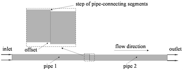
In the installation process of piping system, irregular operation is easy to produce misalignment and form steps between adjacent pipe-connecting segments (as shown in Fig. 1). The geometric model is established by three-dimensional modeling software UG as shown in Fig. 2.
Fig. 1Calculation model of step between adjacent pipe-connecting segments
Mesh is divided into the model by using tetrahedral mesh; prismatic layer mesh is applied at pipe wall and steps; local encryption is performed on the steps; and the model has about 1.2 million grids (as shown in Fig. 3). Through numerically simulating flow field of the adjacent straight pipes by CFD software, the influence of relative offset between the two straight pipes on fluctuation pressure is calculated.
In the case of two straight pipes with the same inside diameter of 80 mm and the length of 1000 mm, keeping flow direction constant, flow velocity of 3 m/s and wall roughness of 0, setting up the turbulence model as LES WALE Model and taking the result of steady state calculation as initial condition to accelerate the convergence of the residual curve, then fluctuation pressure in pipes is calculated by changing the relative offset between two straight pipes.
Fig. 2Geometric model of step of pipe-connecting segments
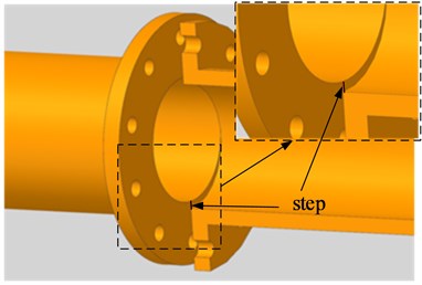
Fig. 3Mesh of model

Fig. 4Pressure field distribution of steps between pipe-connecting segments at different offsets
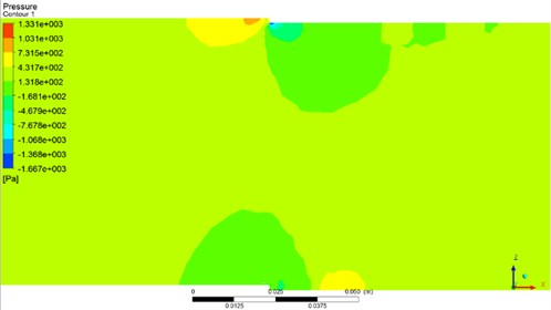
a) Offset of 1.5 mm
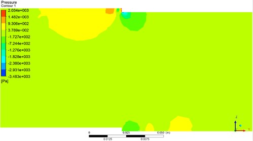
b) Offset of 2.5 mm
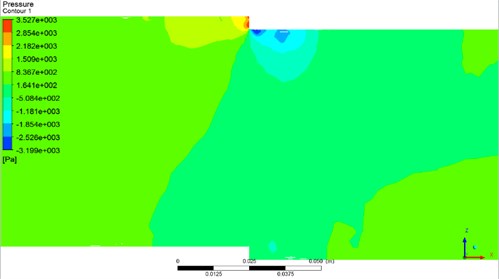
c) Offset of 4.5 mm
Calculation models of pressure field distribution of steps at different offsets are shown in Fig. 4. From the pictures, it is clear that high pressure zone is formed before step while low pressure zone is formed after step, which cause the severe change in turbulent flow field. And with the increase of the step offset, high pressure zone and low pressure zone are more and more obvious.
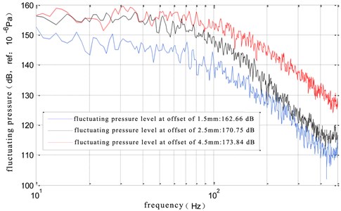
The influence of relative offset between straight pipes on inner wall of pipe is shown in Fig. 5. As is shown in it, with increase of step offset in pipeline connection, the influence of fluctuating pressure is larger and larger. So in process of installing piping system, the flanges’ offset of between adjacent straight pipes should be kept within 1.5 mm.
Fig. 5Influence of relative offset between straight pipes
4. Effect of flow velocity and wall roughness on fluctuation pressure in pipeline
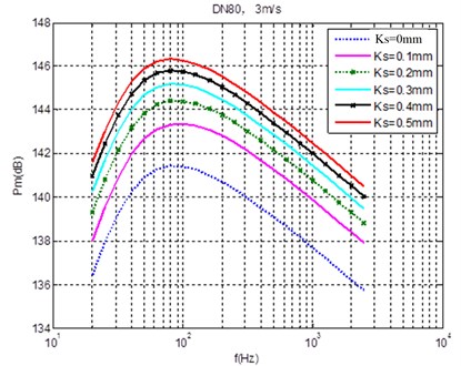
In the case of straight pipe with inner diameter of 80 mm and wall roughness of 0.2 mm, effects of different flow velocity on fluctuation pressure of inner wall of pipeline are calculated as shown in Fig. 6. When flow velocity is respectively 0.5 m/s, 1.0 m/s, 2.0 m/s and 3.0 m/s, the calculated turbulent fluctuation pressure in pipe increases as the flow velocity increases, and the amplitude increased is very obvious. In the case of the same pipe with inner diameter of 80 mm and keeping flow velocity of 3 m/s, effects of different wall roughness on turbulent fluctuation pressure in pipe is simulated as shown in Fig. 7. Fluctuation pressure also increases obviously as wall roughness enlarges.
Fig. 6Effect of different flow velocity on fluctuation pressure under a certain roughness
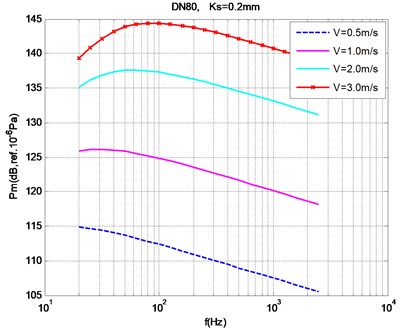
Fig. 7Effect of different wall roughness on fluctuation pressure under a certain flow velocity
5. Conclusions
In this paper, for the fluctuation pressure in ship fluid piping system, based on large eddy simulation and subgrid theory, by CFD numerical simulation method, several factors affected turbulent fluctuation pressure of pipeline are studied and the following conclusions are obtained: turbulent fluctuation pressure increases with the increase of flow velocity, and increases with the increase of wall roughness of pipe. And with the increase of step offset in pipeline connection, the influence of fluctuating pressure is more and more obvious. Therefore, in order to reduce vibration and noise caused by pipe flow, steps should be avoided in the installation process of piping system, and flow velocity should be reduced as far as possible, and wall roughness in pipe should be controlled.
References
-
Zhang Nan, Shen Hongcui, Yao Huizhi, et al. Large eddy simulation of wall pressure fluctuations of underwater vehicle. Chinese Journal of Hydrodynamics, Vol. 2010, Issue 1, 2010, p. 106-112.
-
Qin Wenjin, Xie Maozhao, Jia Ming Investigation on engine in-cylinder turbulent flow and coherent structure based on large eddy simulation. Transactions of CSICE, Vol. 2012, Issue 2, 2012, p. 133-140.
-
Zhang Xiaolong, Zhan Nan, Wu Baoshan Computation of tunnel wall pressure fluctuations using large eddy simulation. Journal of Ship Mechanics, Vol. 2014, Issue 8, 2014, p. 871-881.
-
Meng Fangbin Numerical Simulation of Wall Pressure Fluctuations and Flow-Induced Noise Performance with Submarine Based on the Large Eddy Simulation Method. Shanghai Jiao Tong University, 2011.
-
Zhang Tao, Zhang Yong’ou Structural vibration and fluid-borne noise induced by turbulent flow through a 90°piping elbow with/without a guide vane. International Journal of Pressure Vessels and Piping, Vol. 125, 2015, p. 66-77.
-
Shurtz Thomas, Maynes Daniel, Blotter Jonathan Analysis of induced vibrations in fully-developed turbulent pipe flow using a coupled LES and FEA approach. FEDSM-ICNMM, Montreal, Canada, 2010.
-
Choi Woen-Sug, Choi Yoseb, Hong Suk-Yoon, et al. Turbulence-induced noise of a submerged cylinder using a permeable FW-H method. International Journal of Naval Architecture and Ocean Engineering, Vol. 8, Issue 3, 2016, p. 235-242.
About this article
