Abstract
Wheeled off-road vehicles are known to transmit higher magnitudes of low frequency whole-body vibration (WBV), which have been associated with an array of health disorders among human drivers apart from fatigue and reduced work rate. In this study, the ride performance potentials of a torsio-elastic suspension employed in the front-, rear-, and both axles of an off-road vehicle are investigated. A three-dimensional ride dynamic model of the vehicle is formulated and analyzed under excitations arising from correlated random elevations of two terrain tracks. The model validity is demonstrated on the basis of reported field measured data of a rear-suspended frame-steered articulated forestry vehicle. The ride responses are evaluated in terms of unweighted and weighted root mean square (rms) accelerations along the translational and rotational axes near the driver seat. The results show that fully-suspended vehicle can yield substantial reductions in vibration along all the axes, and suspension in the axle in the proximity of driver cabin is relatively more effective in limited the WBV exposure. It is further shown that the linkage suspension helps preserve roll stability while providing adequate ride performance.
1. Introduction
Wheeled off-road vehicles, employed in the mining, construction and forestry sectors, are known to expose drivers to potentially hazardous levels of low frequency ride vibration of whole-body nature (WBV). Prolonged exposure to such vibration can cause degenerative changes in the spine and greater risks of low back pain [1]. Many field-measurement studies have shown that WBV exposures of drivers of such vehicles exceed the health caution limits defined in ISO-2631-1 [2] and the EC recommended limiting values [3]. The control of transmitted vibration in majority of the small to medium size vehicles have been limited to a suspension at the driver seat. A seat suspension, however, may help limit transmission of only vertical vibration, while such vehicles impose equally large levels of vibration along the lateral as well as longitudinal axes [4].
A number of axle suspension designs have evolved for off-road vehicles for limiting the WBV exposure along multiple axes. The enhancement of ride vibration performance of an axle suspension, however, is achieved at the expense of reduced handling and stability limits. In recent years, cross-connected hydro-pneumatic axle suspensions have been explored to achieve low vertical stiffness for improved ride coupled with high roll stiffness [e.g., 5]. A number of active and semi-active suspension systems have also been proposed to achieve improve ride and handling performance of off-road vehicles [6]. High power demand and unproven reliability of active suspensions in off-road environments, however, continue to be primary prohibitive factors. Pazooki et al. [4] proposed a torsio-elastic linkage suspension for limiting the transmission of multi-axis ride vibration of a forestry skidder, which could also help preserve the roll stability of the vehicle. The study was limited only to the rear suspended articulated vehicle, even though the driver cabin located on the front unit of the vehicle combination. The implementation of the suspension in the front axle or both the axles could yield further reductions in ride vibration.
This paper investigates relative ride performance potentials of a torsio-elastic suspension applied to front-, rear- and both axles of an off-road vehicle. For this purpose, a ride dynamic model of the vehicle is formulated considering different axle suspension arrangements. The model is analyzed considering correlated roughness properties of two terrain tracks. The relative ride performance potentials of different axle suspensions are evaluated in terms of acceleration spectra, and unweighted and frequency-weighted rms acceleration responses.
2. Model formulations
Assuming negligible contribution of frame articulation to ride responses, a 3-dimensional ride dynamic model of an off-road vehicle is formulated with front- and rear-axle torsio-elastic suspensions, as shown in Fig. 1. Each torsio-elastic suspension comprises a lateral link coupling the sprung chassis to the solid axle via two torsion bars oriented along the longitudinal axis, as shown in Fig. 1(a). In the figure, the total sprung mass of the two units is modeled with 5 degrees-of-freedom (DoF) (, , , , and ), while front and rear axle unsprung masses, and , are considered with 3-DoF (, , ; , ). Each suspension link is also modeled as a rigid mass ( = 1, ..., 4), with 3-DoF (, , ; = 1, ..., 4). The radial and torsional elasticity of each torsion bar is modeled assuming linear stiffness and damping along the lateral (, ) and vertical (, ) axis, together with torsional stiffness and damping (, ). The tire is modeled as a three-dimensional point contact model incorporating the potential loss of tire-terrain contact. The equations of motion of the sprung and unsprung masses are obtained as:
Fig. 1Three-dimensional ride dynamic model of an articulated off-road vehicle with front- and rear-axle torsio-elastic suspensions: a) pitch plane, b) roll plane
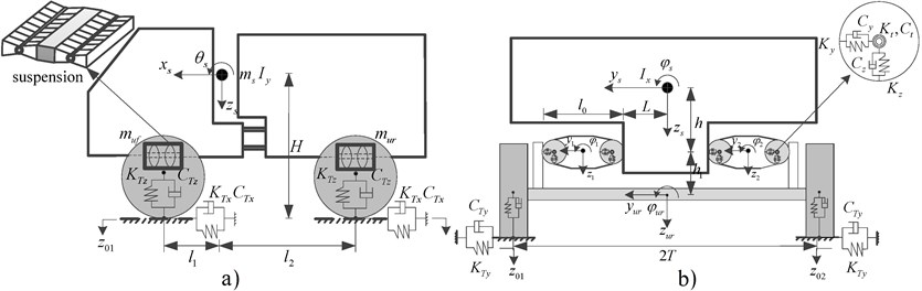
In the above equations, and are roll and pitch sprung mass moment of inertia, and and are roll front- and rear-unsprung masses moment of inertia, respectively. ( = 1, ..., 4) is roll mass moment of inertia of the suspension link, where subscript (1, 2) and (3, 4) refer to front- and rear-axle suspension links, respectively. The dimensional parameters , , (, ), , , and are illustrated in Fig. 1. , and are lateral and vertical forces and roll moments, respectively, acting on the front- ( = 1, 2) and rear- ( = 3, 4) sprung masses, given by:
Similarly, , and are lateral and vertical torsion bar forces and roll moments, respectively, imposed on the front- ( = 1, 2) and rear- ( = 3, 4) axles, which are obtained as:
, , ( = 1, …, 4) are longitudinal, lateral and vertical forces, respectively, developed by tires, and ( = 1, ..., 4) represent elevations of the contact points. Assuming linear properties and loss of contact in the vertical direction, the tire forces are obtained from:
The forestry terrain is assumed undeformable and its spatial roughness power spectral density (PSD) is taken as a power function of spatial frequency , such that, , where and are terrain roughness coefficient and waviness, respectively [7]. Random elevations of two terrain tracks are synthesized assuming high low frequency correlation [4].
3. Results and discussions
The equations of motion are solved under random excitations arising from two terrain tracks considering constant forward speed and coherency cut-off frequency of 1 Hz for the two terrain tracks. The model responses are evaluated in terms of acceleration PSD, and overall rms accelerations. The frequency-weighted rms accelerations near the driver seat are further obtained using the frequency-weightings defined in ISO-2631-1 [2]. The model validity is initially examined using the reported data for the rear-suspended vehicle at a forward speed of 5 km/h [4]. Pazooki et al [4] measured ride responses of a forestry skidder equipped with a rear-axle torsio-elastic suspension, while operating on a forestry terrain at a relative low speed of 5 km/h. The measured data were reported for both the unloaded and fully-loaded vehicles in terms of acceleration PSD and overall rms accelerations along the longitudinal (), lateral (), vertical (), roll () and pitch () axes at the cabin floor beneath the driver seat. In order to examine model validity, the stiffness properties of the front-axle suspension were taken in the order of 1020 so as to simulate the rigidly mounted front-axle, while the model parameters were taken from [4]. The acceleration responses at the driver seat base generally showed good agreements with the measured results for the rear suspended loaded as well as unloaded vehicles. As an example, Table 1 presents comparisons of unweighted and frequency-weighted rms acceleration responses of the loaded vehicle with the measured values. The table also presents the vector sum of accelerations along the -, - and -axes, and the 8-hour equivalent exposure obtained considering total daily exposure of 4 hours, such that, .
Model results for the loaded vehicle are in good agreement with the measured values as seen in Table 1. The deviations in the overall acceleration responses range from 6.3 % in the -axis to 13 % for the -axis. These are likely due to lack of consideration of deformable terrain, neglecting frame articulation joint forces and moments, simplified point contact representation of the tire and assuming linear properties of the torsio-elastic suspension. Similar degree of agreement is also evident in the frequency-weighted rms acceleration responses of the model and the measured data. The deviations between the measured values and model responses range from 5.7 % along -axis to 10.5 % along the -axis. The total rms acceleration and values of the model responses are also comparable with the measured values, as seen in the table.
Table 1Comparisons of unweighted and frequency-weighted rms acceleration values of the rear-suspended loaded vehicle model with the reported measured values [4]
rms acceleration | Axis | |||||||
Unweighted | Measured | 0.85 | 1.26 | 1.00 | 0.79 | 0.74 | ||
Model | 0.79 | 1.15 | 1.13 | 0.84 | 0.79 | |||
Deviation (%) | –7.1 | –8.7 | +13.0 | +6.3 | +6.8 | |||
Frequency-weighted | Measured | 0.75 | 0.95 | 0.60 | 0.56 | 0.52 | 1.80 | 1.27 |
Model | 0.68 | 0.85 | 0.66 | 0.52 | 0.55 | 1.66 | 1.17 | |
Deviation (%) | –9.3 | –10.5 | +10.0 | –7.1 | +5.7 | –7.8 | –7.9 |
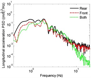
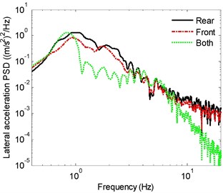
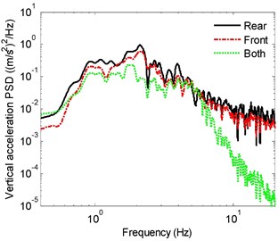
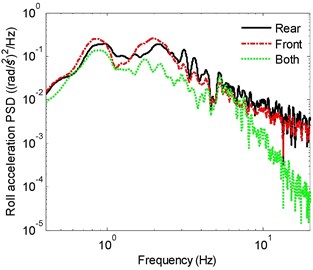
The relative ride responses are subsequently evaluated considering front-, rear- and both axles suspensions. The results are obtained for both the loaded and unloaded vehicle models. As an example, the PSD spectra of -, -, - and -acceleration responses at seat location of the unloaded vehicle model with front-, rear- and both suspended axles are compared in Fig. 2. The responses exhibit peaks in the vicinity of 1, 0.9 and 2.1 Hz, respectively, which are comparable with those reported in [4]. The roll and pitch mode resonances occur in the 0.9 to 1 Hz range. The vertical and pitch response spectra of the rear-suspended vehicle show peaks near 2.1 and 1 Hz, which is attributed coupling between these modes. Similarly, the lateral and roll responses show peaks near 0.9 and 2.1 Hz, which is attributed to coupling between these modes. The predominant frequency of longitudinal vibration is near 1 Hz, which can be associated with the pitch mode resonance. The vertical mode resonance frequency of the vehicle with both suspended axles (1.8 Hz) is lower compared to the front- and rear-suspended vehicles (2.1 Hz). The roll and pitch mode frequencies of the fully suspended vehicle, however, are comparable with those of the front- or rear-suspended vehicles. These suggest relatively smaller effect of torsio-elastic suspension on vehicle’s effective roll stiffness.
The results suggest that the vehicle with front-axle suspension yields better attenuation of vibration along all the translational axes, when compared with the rear-suspended vehicle. The improved ride performance of front-suspended vehicle is especially evident in the lower frequency range and near resonant frequencies. This is due to location of driver seat closer to the front axle. The front-suspended vehicle, however, yields slightly higher roll vibration compared to the rear-suspended vehicle in the vicinity of the roll and vertical mode resonance frequencies, which occur near 0.9 and 2.1 Hz, respectively. This is likely due to relatively higher front-axle load compared to the rear-axle load for the unloaded vehicle, and thereby larger deflection of the front-axle torsion bars. The pitch acceleration response of the front- and rear-suspended vehicle models are quite comparable in most of the frequency range. The results clearly show beneficial performance of the fully-suspended vehicle. Vehicle model with both suspended axles shows substantially lower vibration responses in most of the frequency range along all the axes when compared with those of the front- or rear-suspended vehicles.
The relative ride performance potentials of the front-, rear- and fully-suspended vehicle models are further evaluated in terms of overall unweighted and frequency-weighted rms accelerations (Table 2). The table also presents vector sum acceleration and values. The results are presented for both unloaded and loaded vehicle models. The results suggest that fully-suspended vehicle can yield better ride performance compared to front- or rear- suspended vehicles. The fully-suspended vehicle particularly yields substantial benefit in reducing vertical vibration, due to relatively lower vertical mode frequency (1.8 Hz) compared to 2.1 Hz for the front- or rear-suspended vehicles. The front-suspension, however, yields more effective vibration reduction compared to the rear-suspension. This is especially evident for longitudinal response, which is quite comparable for the vehicle model with front- as well as both suspended axles. For the unloaded vehicle, the values of the front-and fully-suspended vehicle models are nearly 18 % and 27 % lower compared to the rear-suspended vehicle.
Fig. 2Acceleration PSD of acceleration responses of the vehicle model with front-, rear- and both-suspended axles: a) longitudinal, b) lateral, c) vertical, d) roll
a)
b)
c)
d)
The results further show similar performance gains of the fully-suspended vehicle model with the load. Comparisons of ride responses of the loaded and unloaded vehicles show lower sensitive to variations in the vehicle load, irrespective of the suspension configuration considered. The unweighted rms accelerations along all the axes are lower for the loaded front- and rear-axle suspended vehicles compared to the unloaded vehicles. The weighted rms accelerations along -, - and -axes of the loaded front- and rear-axle suspended vehicles are also lower than those of the unloaded vehicles, while the weighted roll and pitch accelerations are slightly higher, which is partly due to the effect of weighting we defined in ISO-2631-1 [2]. The unweighted and weighted rms accelerations of the fully-suspended loaded vehicle along -, -, and -axes are slightly higher compared to the unloaded vehicle, although the deviations are small. The unweighted and weighted rms accelerations along the - and -axes of fully-suspended loaded vehicle are lower compared to the unloaded vehicle, which suggests that the suspension can preserve roll stability under loaded condition.
Table 2Comparisons of unweighted and frequency-weighted rms acceleration values of front-, rear- and both-suspended vehicles at unloaded and loaded conditions
Axis | Unweighted rms acceleration | Frequency-weighted rms acceleration | Unweighted rms acceleration | Frequency-weighted rms acceleration | ||||||||
Front | Rear | Both | Front | Rear | Both | Front | Rear | Both | Front | Rear | Both | |
Unloaded vehicle | Loaded vehicle | |||||||||||
0.64 | 0.81 | 0.62 | 0.53 | 0.70 | 0.52 | 0.55 | 0.73 | 0.65 | 0.46 | 0.65 | 0.55 | |
0.93 | 1.18 | 0.77 | 0.83 | 1.01 | 0.71 | 0.85 | 1.02 | 0.71 | 0.79 | 0.92 | 0.65 | |
1.03 | 1.14 | 0.63 | 0.66 | 0.70 | 0.47 | 0.96 | 1.13 | 0.68 | 0.62 | 0.66 | 0.49 | |
0.79 | 0.83 | 0.47 | 0.40 | 0.41 | 0.28 | 0.74 | 0.81 | 0.43 | 0.43 | 0.48 | 0.25 | |
0.74 | 0.85 | 0.68 | 0.39 | 0.42 | 0.34 | 0.72 | 0.78 | 0.75 | 0.42 | 0.49 | 0.39 | |
1.53 | 1.86 | 1.33 | 1.42 | 1.71 | 1.28 | |||||||
1.08 | 1.32 | 0.94 | 1.00 | 1.21 | 0.91 | |||||||
4. Conclusions
The relative ride performance potentials of a torsio-elastic suspension applied to the front-, rear- and both-axles of an off-road vehicle are analyzed considering correlated random excitations due to two terrain tracks. The results show that application of suspension to the axle closer to the driver cabin yields more effective vibration isolation, while the fully-suspended vehicle yields substantial ride performance benefits. The results further showed low sensitivity of the suspension performance to load variations. Moreover, the torsio-elastic suspension with linkages could help preserve the vehicle roll stability limit.
References
-
Burstrom L., Nilsson T., Wahlstrom J. Whole-body vibration and the risk of low back pain and sciatica: a systematic review and meta-analysis. International Archives of Occupational and Environmental Health, Vol. 88, Issue 4, 2015, p. 403-418.
-
Mechanical Vibration and Shock. Evaluation of Human Exposure to Whole-Body Vibration. Part 1: General Requirements. ISO 2631-1, 1997.
-
Minimum Health and Safety Requirements Regarding the Exposure of Workers to the Risks Arising from Physical Agents (Vibration). European Union Directive 2002/44/EC, 2002.
-
Pazooki Alireza, Rakheja Subhash, Cao Dongpu Modeling and validation of off-road vehicle ride dynamics. Mechanical Systems and Signal Processing, Vol. 28, 2012, p. 679-695.
-
Hua H., Wang L., Qi H., Zhang J. Implementation and Experimental Study of a Novel Air Spring Combined with Hydraulically Interconnected Suspension to Enhance Roll Stiffness on Buses. SAE Technical Paper 2015-01-0652, 2015.
-
Els P. S., van Niekerk J. L. Dynamic modelling of an off-road vehicle for the design of a semi-active, hydropneumatic spring-damper system. Proceedings of the 16th International Association for Vehicle System Dynamics Symposium: Dynamics of Vehicles on Roads and Tracks, Pretoria, South Africa, 1999.
-
Mechanical Vibration. Road Surface Profiles. Reporting of Measured Data. ISO 8608, 1995.
About this article
We acknowledge support from Natural Science Foundation of China (Project No. 51475171).
