Abstract
Device for energy extraction from fluid (air or water) is investigated. The device consists of a one central rotor with energy generator and several plane blades. All blades are connected to the central rotor with gear system which allows automatically change the orientation of their working surfaces to the direction of the incoming fluid flow. It is considered task that axis of the rotor and blades are perpendicular to fluid flow. System has one degree of freedom as rotation angle of central rotor. Theoretical analysis of the one blade interaction with the fluid flow is given. Calculation of system with one blade is done with MathCAD.
1. Introduction
In this work the authors continue studies initiated in previous works on energy extraction from fluid (water or air) [1, 2]. The motion of one-degree freedom system in which the central rotor is kinematic connected with several blades is analyzed (Fig. 2). The blades interact with fluid flow, automatically taking a certain orientation. According to previous studies blades angles and rotor turning angle is related to the following Eq. (1) [2]:
where – initial phase of each blade.
Fig. 1Model of a device investigated before [1, 2]
![Model of a device investigated before [1, 2]](https://static-01.extrica.com/articles/17676/17676-img1.jpg)
Fig. 2A schematic diagram of a device. 1 – rotor; 2 – blades; φ – angle of rotor positions; α – angle of blade positions; O1 – rotor axis; O2– blade rotation axis; F – fluid interaction forces [1]
![A schematic diagram of a device. 1 – rotor; 2 – blades; φ – angle of rotor positions; α – angle of blade positions; O1 – rotor axis; O2– blade rotation axis; F – fluid interaction forces [1]](https://static-01.extrica.com/articles/17676/17676-img2.jpg)
This research analyzes the system interaction with the fluid, without taking into account the central rotor interaction, which partially is described as double pendulum in the works [3, 4].
Before the exploration of the all rotation system dynamics it is need to find one blade and fluid interaction forces. At first it is to find out reduction forces to blade rotation axis O2. In this report is studied the case when the initial phase is zero, , or (Fig. 2):
1.1. Simplification of fluid flow interaction forces with one blade
For interaction forces simplification the one small ribbon of blade with length is observed (Fig. 3). Then normal component of interaction force at the distance from center depends of normal velocity component in square Eq. (3) [4]:
where: – constant including density of fluid, width of plate, drag coefficient in normal direction; – angular velocity of central rotor; – radius of center ; – flow velocity.
Similarly, the tangential component will be Eq. (4):
where: – constant including density of fluid, width of plate, drag coefficient along plate.
Fig. 3A schematic diagram of interaction force calculation. V – flow velocity; ω – angular velocity of rotor; φ – angle of rotor positions; α=(π/4+0,5⋅φ) – angle of blade position; Rn – fluid interaction normal force; Rt – fluid interactions tangential force
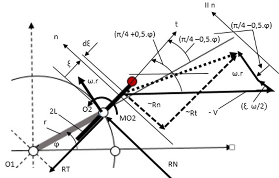
Accordingly, to classical mechanics there can be found out reduction forces and moment of forces in the center in the following Eqs. (5-7) [5, 6]:
where , , – components of forces vector and forces moment in point ; 2 – length of blade; sign1, sign2 – +1 or –1, that depends of local interactions directions (see Fig. 3); – width of blade.
Here problem exists to find integrals Eq. (5-7) because sign1 and sign2 switch functions depend of systems parameters and motion parameters (, ).
In this report the simple case is observed when width of plate is small 0) and sign1 = +1.
Then from Eq. (5), (7) can be find out:
Formulas Eq. (8), (9) can be used for rotor rotation motion investigations.
1.2. Differential equation of rotor motion with one blade
For system with one degree of freedom (angle ) by using kinetics energy exchange theorem can be find out differential equation of motion [5, 6]:
where: – constant including system mass, moments of inertia rotor and blade; – moment of generator and of resistant forces; – constant of gravitation interaction which takes into account rotation axis orientation and location of center mass.
Eq. (10) may be investigated by computer, checking parameters sign1 = +1. If is large, system does not rotate but starts to move in pendulum vibration regime.
1.3. One blade systems modelling with Math CAD
Some diagrams of modelling with explanations are shown in Fig. 4, Fig. 5.
Fig. 4Results of modelling with MathCAD with sign1 = +1 (from rest position till angle φ=3π/2)
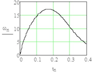
a) Angular velocity in time domain
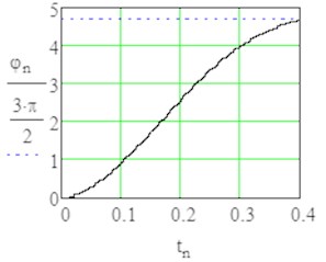
b) Turn angle in time domain
Fig. 5Results of modelling in stationary rotation with sign1 = +1 by angle φ= 0 till 3π/2
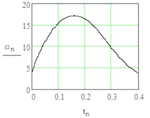
a) Angular velocity in time domain
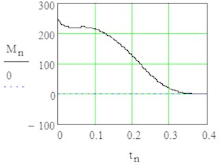
b) Fluid interaction moment
2. Conclusions
The possibility to use double pendulum system with additional constraint for energy extraction from fluid is established. The analytical formulas for fluid interaction with rotating blade are given. In future it allows investigated more complicated system with different number of blades and different positioning angles. Results of this report can be used for systems parameters optimization.
References
-
Viba J., Noskovs S., Beresnevich V. Method for Control of Operation Condition of Wind Turbine and Device for Its Realization. Patent LV 15038, Republic of Latvia, Int.Cl. F03D7/06, Izgudrojumi, Precu Zimes un Dizainparaugi, No. 12, 2015, p. 1756
-
Viba J., Noskovs S., Beresnevich V., Dobelis J. New devices for energy extraction from air flow. Proceedings of the Engineering for Rural Development, Jelgava, 2016.
-
Viba J., Vitols D., Tsyfansky S., Beresnevich V., Noskovs S., Jakushevich V. A vibrating object interaction with fluids. Scientific Journal of Riga Technical University, Transport and Engineering, Mechanics, Riga Technical University Press, 2015, p. 7-11, (in Latvian).
-
Ozolins O., Cipruss V., Viba J., Jakovlevs O. Double pendulum motion analysis in variable fluid flow. Proceedings of the Engineering for Rural Development, Jelgava, 2016.
-
Arnold V. I. Problem in Mathematical Methods of Classical Mechanics. 2nd Ed., Springer-Verlag, New York, 1989, p. 109.
-
Goldstein H., Poole C., Safko J. Classical Mechanics. Third Edition, Addison-Wesley, 2002, p. 647.
About this article
