Abstract
In order to develop a compact precise device for studying the rheological properties of Newtonian and non-Newtonian fluids in a wide range of pressures, temperatures and shear rates, in the present paper a new method and design of a vibro-inertial viscometer is presented. A simulation model was developed to calculate the flow of a viscous uncompressible fluid in a torus-shaped channel under the influence of vibration. The effect of boundary flow of low viscosity fluids is identified and the relationship between the vibrational frequency and main characteristics of the viscometer is shown.
1. Introduction
Existing means of fluid’s viscosity measurements are in a vast majority of cases based on simplified flow models [1]. The most widespread assumption here is that the fluid has Newtonian properties. Usually the static characteristics are measured during the tests, i.e. flow rate, friction torque, etc. However, not always the condition of homogeneity of thermomechanical values’ distribution is met. The majority of precise viscometers can be divided into two main classes: capillary and rotational [2]. Other types of devices, including orifice, falling ball, vibrational and ultrasonic viscometers [3], are simple but the methods of viscosity measurement are to a great extent based on various assumptions, thus are not always applicable.
In [4] the inertial method and the device are shown to measure viscosity in a torus-shaped flow area of a fluid. Such area provides enough simplicity and universality of a mathematical model of the Newtonian and non-Newtonian fluids’ flow and homogeneity of the thermomechanical values’ distribution. Herewith, the basic disadvantages of this design are a relative complexity of reaching high shear-strain rates by means of inertial motion, complexity in terms of size optimization, because of the requirement of a certain ration between the torus’s size and the channel’s size, and, finally, the influence of inertia forces of moving parts on the measurement results. In order to keep the advantages and reduce the disadvantages, in the present paper a new type is suggested – vibro-inertial viscometer.
2. Conception and design
A new method of viscosity measurement is suggested which can be applied for studies of rheological properties of non-Newtonian fluids in a wide range of pressures, temperatures and shear rates. The device called vibro-inertial viscometer is a torus mounted on an elastic or magnetic support with a driving and measuring system. An oscillation is transmitted to the torus with a fluid under study inside, and the main characteristics of this motion, i.e. torus rotation angle and oscillation power, are used to calculate the viscosity of the fluid. The measured values as functions of time are used as input parameters in a simulation model. The comparison of the experimental and numerical characteristics allows determination of viscosity and rheological model of a fluid under study. Fig. 1 shows the sketch of a vibro-inertial viscometer.
Fig. 1Sketch of a vibro-inertial viscometer: support (1), T-shaped screw for a vibrator attachment (2), torus (3), displacement sensor (4), base (5), quick-detachable connection for fluid inlet and outlet (6)
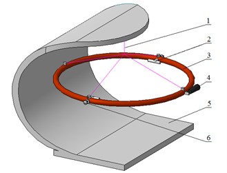
To develop a prototype of a viscometer it is necessary to determine the mass and size characteristics of a torus, driver and measuring system parameters, and also to determine the ranges of viscosity, pressure, temperature and shear rate of the fluids under study.
3. Mathematical model
The main equations which describe the flow of a fluid, are the Navier-Stokes equation, energy equation and the continuity equation [5]. To simplify the equations, the curvilinear coordinate system is used: – radial coordinate in a cross-section of a torus’s channel, – angular coordinate in a cross-section perpendicular to the torus’s axis of symmetry, – angular coordinate in a cross-section of the torus channel. The coordinates are characterized by the following Lamé coefficients [6]: , , . It is assumed that the velocity of the fluid flow in these coordinates has one non-zero component , so the continuity equation takes a simple form . Due to symmetry of the flow area, the following conditions are also met for pressure and temperature:, . Taking these assumptions into account, the Navier-Stokes and energy equations’ projections can be simplified, the resulting equations are described in high detail in [7].
The dimensionalization procedure of the main equations was carried out in accordance to the chosen character geometric, cinematic and static parameters. From the motion and convective thermal conductivity equations the homogeneity conditions [5, 8] were determined for the pressure and temperature distribution, which are shown in [7]. In the present case of a problem under study, the projection of the Navier-Stokes equation on is of particular interest:
where is the Strouhal number, is time, is the Reynolds number, is the kinematic viscosity, , are dimensionless coordinates, , are dimensionless Lamé coefficients, , are geometry parameters.
Considering the homogeneity condition of the pressure and temperature distributions, obtained in [7], namely for the order of magnitude of the geometric parameter , the Eq. (1) for the process under study can be written in a simplified dimension form:
4. Numerical model
For a numerical solution of Eq. (2) it is convenient to use the control volume method [9, 10]. The initial and boundary conditions are determined by the torus’s motion law and the condition of axis-symmetrical fluid motion in the torus channel , , . The division of the calculation area into of control volumes (CV) is implemented so, that every CV contains a calculation point in its centre. In the Fig. 2 a method of discretization of the calculation area is shown.
Fig. 2Discretization of the calculation area
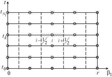
By means of integrating Eq. (2) with respect to every control volume and by means of substituting the derivatives of first order with the corresponding finite differences, the following system of equation is obtained:
To compare the results, the equation in question can be solved using the finite differences method. Then, the discrete analog of Eq. (2) is:
It has to be noted, that the solution using the CV method is more accurate and does not require a big number of calculation points [9].
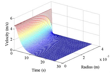
The Fig. 3 depicts the test results of the developed mathematical model and calculation program. To check the results experimentally, a number of toruses were developed with radius 0.44 m and channel radiuses 4.5, ..., 6·10-3 m. The toruses were made of transparent material, and the test fluids (water and kerosene) were colored with fine particles to visualize the process of the fluid flow. During the experiment the torus reached the speed of 100, …, 200 rpm, and then abruptly stopped. The duration of inertial fluid motion was calculated and measured.
Fig. 3Testing of the developed model of the inertial fluid flow in a torus: a) fluid flow velocity over the channel’s width and time, b) comparison of the calculated and experimental time of the flow duration in the torus
a)
b)
The experimental results showed that the duration of the fluid flow does not depend on the velocity of the torus , but can be definitely determined by the dimensional criterion and this proves Eq. (2) correct. The calculation results show a good match to the experimental results, but the control volume method showed higher accuracy.
The following study was done with the use of the simulation model of the vibro-inertial viscometer.
5. Results and discussion
We have studied the vibro-inertial viscometer simulation model with the following parameters: torus with the radius 0.1 m and torus channel radius 8.5·10-4 m. Torus’s wall thickness 5·10-4 m, material – carbon fiber, centroidal moment of inertia 1.95·10-5 kg·m2. During operation the torus oscillates around its rotational axis in accordance to a harmonic law with the given amplitude 4·10-3 m and frequency 50, ..., 200 Hz. It is assumed that the torus oscillates only around its axis of symmetry, and there is only the laminar flow in the torus according to the Eq. (2). As test fluids, the liquid oxygen, water, industrial oil I-12A of the same viscosity class as, for example, oil “Shell Vitrea 22”, were chosen.
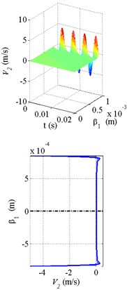
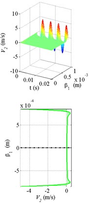
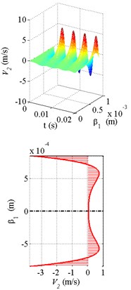
Fig. 4The calculation results of the velocity distribution and velocity profiles at a fixed moment in time with the torus oscillating at 200 Hz: a) liquid oxygen, b) water, c) oil
a)
b)
c)
In the Fig. 4 the results of the fluid flow calculation with the torus oscillating at 200 Hz are shown. The torus’s motion is transmitted from the boundary layers of the fluid to the torus’s channel’s center. High oscillation frequency and relatively low viscosity can help occurrence of the boundary flow, i.e. such flow, where a thin boundary layer of the fluid moves, while the rest remains motionless. This has a positive effect on the value of shear rate and, consequently, increases the friction force. The Fig. 4(b) shows the boundary flow effect for the liquid oxygen and water.
The demand for a viscometer depends largely on the level and width of the input parameters’ range and the range of possible measurements, the accuracy of the method and accuracy of the device itself.
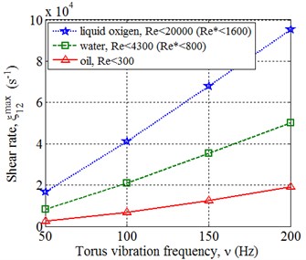
The Fig. 5(a) shows the results of shear rate calculation, and it can be seen, that at 200 Hz the order of magnitude of the shear rate is 104, ..., 105 1/s depending on the fluid’s viscosity. Here, the low viscosity fluids approach the turbulent flow (the alternative Reynolds number is calculated considering the boundary flow effect), and the more viscous fluids allow a few times higher oscillation frequencies. The increase of the amplitude of the oscillations causes the similar effect. So, the vibro-inertial viscometer can be classified as high-speed.
Fig. 5Results of the calculation with various oscillation frequency of the torus: a) shear rate amplitude, b) amplitudes of the friction forces power and the inertia forces of the torus ratios
a)
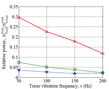
b)
The force resistance of a fluid is expressed by the friction force on the side of the torus, and this resistance has to be registered during the operation of the viscometer. Moreover, the inertia forces of the torus and joint moving parts of the viscometer cause a significant force resistance. From the Fig. 5(b) one can see that the power of the inertia forces is larger than the power of friction forces. This complicates the procedure of the force resistance measurement of a fluid, particularly in case of low viscosity fluids and high frequency oscillations. It has to be noted, that the oscillations of the friction forces’ power have an amplitude two times higher than the oscillations of the torus, so the frequency response shows that the contribution of these powers can be separate.
6. Conclusions
The suggested design of a vibro-inertial viscometer creates a base for development of a compact device for the study of rheological properties of Newtonian and non-Newtonian fluids in a wide range of pressures, temperatures and shear rates. As a result of a series of calculation tests for low viscosity fluids the effect of a boundary flow was identified, due to which the shear rate and the efficiency of measurements increase. Theoretically, the same effect can be achieved testing any fluid by means of choosing certain parameters of the tests. It was also determined that the higher the frequency of oscillations, the more rapidly the power of inertia forces of the moving parts of the rig increases in comparison to the power of fluid friction forces. This disadvantage cannot be fully eliminated, however can be reduced by means of reducing the mass characteristics of the moving parts, increasing the accuracy of the measuring equipment and applying modern methods of signal processing.
References
-
Middleman S. The Flow of High Polymers. Continuum and Molecular Rheology. Intersciernce Publishers, 1968.
-
Viswanath D., Ghosh T., Prasad D., Dutt N., Rany K. Viscosity of Liquids. Springer, 2007.
-
Wilkinson M. A. Non-Newtonian Fluids. Fluid Mechanics, Mixing and Heat Transfer. Pergamon Press, 1960.
-
Savin L. A., Kornaeva V., Kornaeva E. P., Antonov P. G. Inertial Method of Viscosity Measurement. State University – ESPC Assignee, Russian Federation Patent RU 2517819, 2014.
-
Milne-Thomson L. M. Theoretical Hydrodynamics. 4th Edition, Macmilan and Co. Ltd., London, 1960.
-
Korn G. A., Korn T. M. Mathematical Handbook for Scientists and Engineers. Dover Publications, 2000.
-
Kornaeva E., Kornaev A., Savin L. Inertial method of viscosity measurement of the complex rheology medium. Procedia Engineering, Vol. 150, 2016, p. 626-634.
-
Bair S. High Pressure Rheology for Quantitative Elasto-Hydrodynamics. Elsevier, 2007.
-
Patankar S. V. Numerical Heat Transfer and Fluid Flow. Hemisphere Publishing Corporation, New York, 1980, p. 148.
-
Savin L., Kornaeva E. Modeling of fluid flow in the cone seal. Procedia Engineering, Vol. 39, 2012, p. 132-139.
About this article
This work was partly supported by the Ministry of Education and Science of the Russian Federation under the Project No. 363 of a part of the state task for the Oryol State University named after I. S. Turgenev (mathematical and numerical models, results and discussion) and by the Russian Science Foundation under the Project No. 16-19-00186 (conception and design of the viscometer). The authors gratefully acknowledge this support.
