Abstract
This article presents the results of the study of the motion of an electromechanical system in the presence of an elastic link and delay in the negative feedback loop of a servo drive. We propose a model of the drive with a digital angular position control system of the working body. The servo drive model takes into account the dynamics of the processes occurring in the collector of the DC motor, stiffness of the elastic link that transfers torque from the electric motor to the working body, the influence of the digital sensor of the angular coordinate of the working body and delay in the digital control system on the operation of the drive. Results of mathematical modeling of the operation of the studied model are presented.
1. Introduction
The use of digital electronic components (microcontrollers, digital sensors of physical quantities) in drives transforms these systems into the digital servo systems. The digital servo system is an example of a nonlinear impulse automatic control system [1-3]. Digital systems operate in the converter mode “digital code to physical quantity” (e.g., position or speed of the current state of the controlled system) and the converter mode “current status of control object to digital code”. An important criterion for evaluating the performance of digital servo systems is the value of the period of delay time in the feedback loop, caused by the operation of digital electronic components in the following processes: analogue-to-digital and digital-to-analogue processing of signal, arithmetic, logic and tabular conversions of a digital code (for example, conversion of Gray code into straight binary code), generation of a pulse-width modulation (PWM) signal for the control of the servo drive actuators and implementation of service procedures of the control system (for example, output of data about the current state of the system). In other words, the delay period is the time spent by the digital components to process signals. The smaller the delay period, the greater the speed of the system.
Sensitivity, range of measurement and bandwidth of the sensors affect the accuracy of the operation of servo drives. When digital sensors are used in servo systems the discreteness of the output digital signal and sampling rate also affect the operation of the systems. The discreteness of the output signal of the sensor is determined by resolution expressed in units and tens of bits. The use of a digital sensor with low resolution in the servo system reduces its sensitivity and can cause oscillatory processes [4-6].
In this work we present a model of an electric servo drive with a digital control system of the working body’s angular coordinate that takes into account the stiffness of the shaft, which transfers torque from the electric motor to the working body and delay in the negative feedback loop of the electric servo drive.
2. Description of the object of study
The object of study is the influence of the actions of delay in the negative feedback loop, stiffness of the elastic link that transfers torque from the motor to the working body and the size of dead zones of digital sensors due to their resolution capabilities on the operation of the servo system of the electromechanical drive (Fig. 1). Thus, we consider a servo system with a DC collector electric motor (EM). The reference signal former, digital signal processing block, digital comparator and digital regulator block (Fig. 1) are programmatically implemented on the microcontroller [7].
The reference signal former (Fig. 1) generates a certain value of the required angular displacement of the working body, . The task of the sensor – digital encoder (DE) is to measure the angular displacement of the working body of the actuating mechanism, .
The difference:
is the position (angular coordinate) error, . The task of the servo system is to minimize this error i.e. 0.
Fig. 1Diagram of the servo system of the electric drive during control of the angular coordinate of the working body
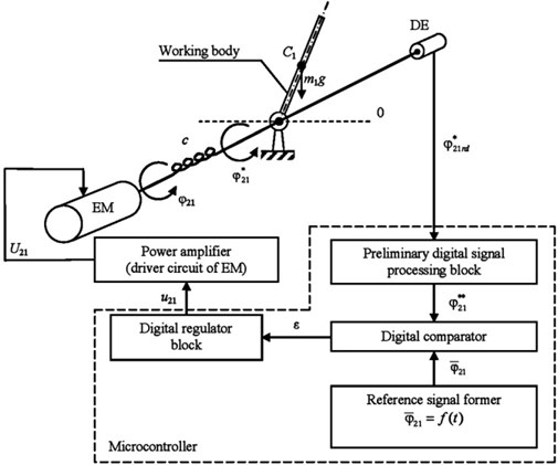
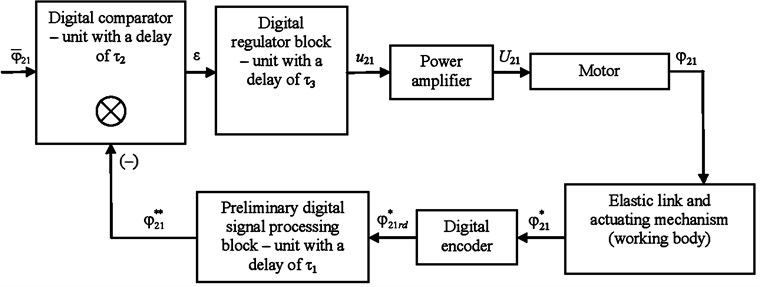
We assume that the preliminary digital signal processing block with a time delay of , the digital comparator with a time delay of , the digital regulator block with a time delay of and the reference signal former with a time delay of (Figs. 1, 2) are units of pure time delay.
We take 10·10-3 s (when we use an absolute 8-bit encoder Bourns ACE-128 is connected to the interface of a microcontroller – Atmel ATmega32u4 via an input-output expander microchip Microchip MCP23008 and using a data rate of 100 kb/s) for the unit of the preliminary digital signal processing block (including the time taken to receive the sensor signal).
For the digital comparator we take 10·10-6 s, for the digital regulator block – the value 10·10-6 s and for the reference signal former – the value 10·10-6 s.
Since the maximal value of delay is period of the unit of the preliminary digital signal processing block, we should take period as the overall delay period in the negative feedback loop of the servo drive. All units operate asynchronous and simultaneously.
The period of delay for digital devices amounts to tens – hundreds of milliseconds.
The functional diagram of the operation of the servo drive with the angular coordinate control of the working body is shown in Fig. 2.
Encoders are one of the digital devices for measuring the angular coordinate. This type of sensor is a coded position sensor. The majority of the commercially available code encoders use the Gray code or similar codes, in which the reading error does not exceed the value of the least significant bit of the angle code. The disadvantage of the sensors using the scale with Gray code, or similar, is the need for decryption of the special code into straight binary code that is proportional to the measured angular coordinate.
Fig. 2Functional diagram of the operation of the servo drive with the angular coordinate control of the working body
In order to convert a special code into straight binary code, it is necessary to use table lookup, as a result of which each value of the special code, , is assigned to a binary code . The shaft of the encoder, Bourns ACE-128, can occupy 128 different positions that correspond to the special code. Thus, the length of the binary code, Bourns ACE-128, obtained after table lookup, is 7 bits.
The expression for the conversion of encoder binary code into the encoder shaft rotation angle:
where: is the angle of rotation of the encoder shaft in degrees, – the value of binary code (number of the shaft’s position).
One of the methods of varying the supply voltage, is the application of pulse-width modulation (PWM).
We define the pulse ratio of the PWM signal as the ratio of the duration of the electric pulses, μ to the pulse repetition interval, . The pulse ratio, determines the relation between the peak and average values of voltage and current pulses.
The value of the pulse ratio is less or equal to unity:
A PWM signal, with pulse ratio, enters the input of the power amplifier (Figs. 1, 2) that converts it into the supply voltage, of the motor. The supply voltage, is maximum when 1 and consequently the angular velocity of the shaft’s rotation, is also maximum. The value of is directly proportional to the value of pulse ratio of the PWM signal. Further, under the PWM, we imply its pulse ratio, .
3. Mathematical model
The system of equations describing the operation of the electromechanical system (Fig. 1) taking into account the presence of an elastic link, time delay in the negative feedback loop of the servo drive and the digital encoder with a dead zone can be presented in the form of system of Eq. (4):
where: – angular coordinate of rotation of the motor shaft of the electromechanical drive, rad; – angular coordinate of rotation of the mechanism’s working body, rad; – total moment of inertia on the axis of the motor, kg·m2; – mass of the working body of the actuating mechanism, kg; – length of the working body of the actuating mechanism, m; – moment of inertia of the actuating mechanism, kg·m2, ; and – inductance, and resistance, Ohm of the electromechanical drive motor respectively; – torque of the electromechanical drive motor, N·m; – current of the armature of the electromechanical drive motor, А; and – coefficients of proportionality electric motor of the electromechanical drive; – control voltage of the motor, V; – error in the angular coordinate of rotation of the working body, rad; – pulse ratio of the PWM signal; – value of the required angular displacement of the working body, rad; – time, s; – value of the time delay period of the digital signal processing block, s; – value of the time delay period of the of the digital comparator, s; – value of the time delay period of the digital regulator block, s; – value of the time delay period of the reference signal former, s; – angular coordinate of the rotation of the working body of the actuating mechanism measured by the encoder and calculated at 0, rad; . – error in the angular coordinate of rotation of the working body evaluated at 0, rad; . – pulse ratio of the PWM signal evaluated at 0; – value of the required angular displacement of the working body, evaluated at 0, rad; – spring constant of the elastic link between the electric motor and the working body, N/m; – proportional regulator coefficient; – size of the dead zone of the digital encoder, 0,049 rad; – number of the different positions for the encoder, Bourns ACE-128, 128; – number of current positions of the encoder shaft, , 0…1.
4. Results
To obtain the data describing the operation of the electromechanical system the mathematical modelling was implemented in MathWorks MATLAB using the system of Eq. (4). The mathematical modelling process was carried out at following values of the model parameters: 1 Ohm, 1·10-6 H, 1·10-6 kg·m2, 12 V, 209 rad/s, 0.6025 N·m, 1 A, 6.025 N/m, 0.1, 10·10-3 s, 10·10-6 s, 10·10-6 s, 10·10-6 s, 128, 0,049 rad, 0.1 kg, 0.2 m, the total period of mathematical modelling is 2.5 s and the fixed time step – 1·10-6 s.
The results of mathematical modelling are presented in Fig. 3-7.
Fig. 3The diagrams φ-21(t), φ21**(t) and εt
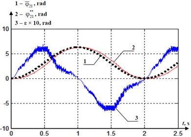
Fig. 4The diagrams φ21(t), φ˙21(t) and φ¨21(t)
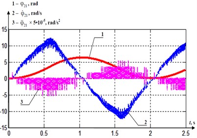
Fig. 5The diagrams φ21*(t), φ˙21*(t) and φ¨21*(t)
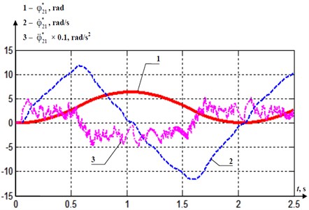
Fig. 6The diagrams of εmax(τ1) at: 1) τ2=τ3=τ4= 1·10-6 s, 2) τ2=τ3=τ4= 1·10-3 s, 3) τ2=τ3=τ4= 10·10-3 s
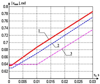
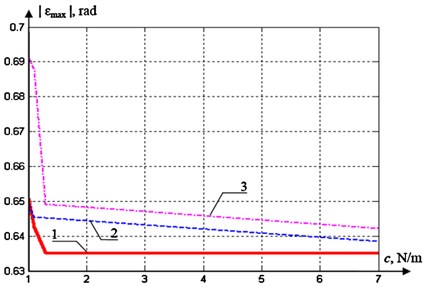
Fig. 7The diagrams of εmax(c) at: 1) τ1=τ2=τ3=τ4= 1·10-6 s, 2) τ1=τ2=τ3=τ4=1·10-3 s, 3) τ1=τ2=τ3=τ4= 10·10-3 s
5. Conclusions
The results of mathematical modelling show that an important criterion for evaluating the performance of the digital servo system is the value of the period of delay in the feedback loop. The smaller delay period present, the greater the operating precision of the digital servo system. The repetition rate of the error ε peaks (Fig. 3) depends on the period of delay ( 10·10-3 s) in the feedback loop. The absolute maximal error value is determined by the size of the dead zone of the digital encoder (), and the angular velocity of rotation of the mechanism’s working body. If the delay periods , , , by orders of magnitude are smaller than the rotation period of the mechanism’s working body, it means that the servo drive can function stably. Figs. 4, 5 demonstrate the time dependences of the mechanical characteristics of the rotation of the motor shaft of the electromechanical drive and rotation of the mechanism working body. These mechanical characteristics are significantly dependent on the delay in the feedback loop. The angular velocity and angular acceleration characteristics are susceptible to the delay in the feedback loop, .
Fig. 6 presents the dependence of the absolute maximum value of ε on the value of at the accepted model parameters. The diagram disposition is explained by various combinations of the delay periods , and . The smaller the values of these delay periods as compared to , the bigger the absolute maximal value of at identical values of . If the delay period, is smaller than the delay periods, , and , the absolute maximal value of is invariable.
Fig. 7 shows the dependence of the absolute maximal ε value on the value at the accepted model parameters. The diagram disposition is explained by various combinations of the delay periods , , and . The smaller these delay periods are, the smaller the absolute maximal value of at identical values of . Since the value of increases, it is clear that the absolute maximum value of tends to its minimum value that is provided by certain delay periods , , and .
References
-
Jatsun S. F. Locomotion control method for patients verticalization with regard to their safety and comfort. Proceedings of the 26th DAAAM International Symposium on Intelligent Manufacturing and Automation, 2015, p. 107-112.
-
Astrom K. J. Advanced PID Control. ISA – The Instrumentation, Systems, and Automation Society, 2006, p. 460.
-
Jatsun S. F. The modelling of the standing-up process of the anthropomorphic mechanism. Assistive Robotics: Proceedings of the 18th International Conference on CLAWAR, 2015, p. 175-182.
-
Panovko G. Y. Simulation of exoskeleton sit-to-stand movement. Journal of Machinery Manufacture and Reliability, Vol. 45, Issue 3, 2016, p. 206-210.
-
Jatsun S. F. Modelling of exoskeleton movement in verticalization process. New Developments in Pure and Applied Mathematics: Proceedings of the International Conference on Pure Mathematics – Applied Mathematics, Vienna, Austria, 2015, p. 83-87.
-
Jatsun S. Study of Controlled Motion of Exoskeleton Moving from Sitting to Standing Position. Advances in Robot Design and Intelligent Control, Springer International Publishing, 2016, p. 165-172.
-
Jatsun S. Parameter optimization for exoskeleton control system using Sobol sequences. Proceedings of the 21st CISM-IFToMM Symposium on Robot Design, Dynamics and Control, Springer International Publishing, 2016, p. 361-368.
-
Levin Mindy F. Progress in Motor Control – Skill Learning, Performance, Health, and Injury. Springer, 2014.
-
Phillips Charles L. Digital Control System Analysis and Design. 4 Edition, Pearson Publishing, 2014.
About this article
This work is financially supported by the Russian Science Foundation, Project No. 14-39-00008 “The Establishment of the Research Laboratory of Modern Methods and Robotic Systems to Improve the Human Environment”.
