Abstract
The paper is devoted to the experimental check of a control algorithm for automatic adjustment of oscillations of a mechanical system to the resonance mode. Oscillations of the system are excited by rotating an unbalanced rotor of an asynchronous electric motor. Working principle of the control system is based on measuring a phase shift between oscillations of the system and an excitation force.
1. Introduction
One of the basic principles of creation of power efficient vibrational machines consists in using a resonant mode of the working body oscillations. However, in certain cases, there is a problem of ensuring the stability of the resonant mode of oscillation associated with process load fluctuations, non-linear characteristics of the mechanical parts, nonlinear character of interaction between a working body and work environment, features of interaction between AN exciter and a vibrodrive. To the greatest extent it relates to machines with an inertial (unbalanced) vibration exciter. For this exact reason the most vibrational technological machines with inertial vibration exciter operate on below-resonance or above-resonance modes [1-3].
By now the problem of stabilizing the resonant vibration mode in machines with DC motor has been well enough studied. Adjustment and maintenance of the resonant mode for machines of this type is provided by a control system of angular velocity of the motor by changing excitation current or supply voltage [4].
However, there are no reliable and effective control principles and algorithms to automatically adjust vibrational machines driven by asynchronous electro-motors to the resonant mode, with such motors being most commonly used in machines of this purpose.
The aim of the work is to develop an experimental model of a system to control asynchronous motor rotational frequency, which provides automatic adjustment of the machines oscillation to the resonance mode, based on the control algorithms proposed by the authors in [5, 6].
2. Object of the study
Previously, in [5, 6] the authors proposed control algorithms to automatically adjust to a resonance mode a single-mass vibration machine, with its working body performing unidirectional oscillations excited by an unbalanced exciter driven by an asynchronous motor. For experimental testing of these algorithms, in the laboratory of vibromechanics of Mechanical Engineering Research Institute of the RAS, an experimental model of vibration machine has been created as shown in Fig. 1. It represents a resiliently fastened platform with two almost identical asynchronous motors (type AИP-56B4) mounted on the platform. Both motors are supplied from a single inverter of type FR-D740 MITSUBISHI. Both ends of each motor shaft are equipped with discs of identical masses and eccentrics.
Due to geometrical and force symmetry of the structure only unidirectional oscillations of the platform are excited in case of synchronous antiphase rotation of debalances.
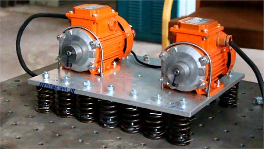
Fig. 1. Experimental model of a vibrational machine
3. Problem statement
We consider the situation when for given frequency of power supply under synchronous rotation of the motors with the frequency different from resonant frequency of the platform oscillation, it is necessary to automatically tune the system to resonance. It seems that such a formulation of the problem is similar to problems arising in a real situation, when for initial resonance tuning, due to changes of the mass of the system, for example, a withdrawal from the resonance occurs, and the control system is to tune to a new resonance regime automatically.
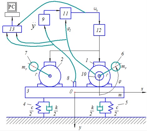
Fig. 2. Principle scheme of a vibrational machine with control system
4. Control system
A principle scheme of the machine with a control system is shown in Fig. 2. The platform 3 together with motors 1 and 2 is considered to be a perfectly rigid body of mass symmetrically supported by viscoelastic dampers 4 and 5 with linear characteristics defined by stiffness coefficient and damping coefficient . Debalances of the rotors 6 and 7 have identical masses and eccentricity . Motion of the system is described relatively to a fixed coordinate system with the origin at the center of mass of the system in static balance. Vertical axis is directed downward, with the angles of rotation of the rotors being measured from positive direction of the axis in a counter-clockwise direction.
It is assumed that the rotors rotate synchronously and in phase, but in opposite directions. Thus due to geometrical and power symmetry the platform performs only unidirectional vertical oscillations. In this case a steady motion of the system can be describe by linear equation:
where – is a platform center of mass coordinate, , – the natural frequency of the system, – a steady rotational speed of rotors.
Control system work is based on an algorithm, described in details in [5]. According to the algorithm we consider phase angle between the response displacement and the excitation force as a controlled variable which should be equal to at resonance. As a control parameter we consider frequency of the supply voltage, supplied to the motors via a frequency inverter 12 that controls the rotational speed of the rotor. For the sake of simplicity of the control system it is assumed that the slip is negligible in the asynchronous motor at the regimes considered. In this case and are related by ratio , where – is the number of pole pairs of the asynchronous motor. Then a correction value of supplied voltage frequency is determined by formula [5]:
To determine the phase shift simultaneous measurements of vertical displacements of the platform and exciting force are performed. For measuring vertical displacement a piezoelectric accelerometer 8 (type KD-35, MMF, GDR) with subsequent double analog integration of its signal by a matching amplifier 9 (type SM-10, RFT, GDR) is used. Synchronous in-phase rotation of both motors leads to excitation of unidirectional oscillation of the platform with a vertical force steady-state oscillations of the system, this force is determined by angle of rotation of one of the rotors. The angle is measured by angular position sensor 10 – incremental encoder (type E40HB – 2000 pulses per revolution, Autonics, Korea), mounted on the right-hand motor shaft in the model considered (Fig. 2). Mathematical processing of measured signals is carried out in a programmable microcontroller Atmel SAM3X – block 11, in which according to algorithm [5] the phase angle is determined in each cycle of oscillations. The moment for the system to reach a steady-state oscillation mode is determined by a change in value of the phase shift in the last periods of oscillation of the system (this value affects both accuracies of adjustment and regulation time and usually it is chosen empirically). In case of , where – predetermined accuracy of determining steady state, oscillation of the system is assumed to be steady, and the regulation cycle starts.
First, the control system checks the resonance condition , where – predetermined regulation accuracy. Then, in case of the system is not at resonance the correction value of supply voltage frequency is estimated by presented above formula.
Note that damping coefficient , part of formula for , was found experimentally while experimental analysis of the oscillogram of convergent free oscillations, excited by a single impact impulse.
After correction value is found, a corresponding control signal is sent to a frequency inverter 12. The regulation cycle is repeated if necessary.
Registration of both oscillations and control signals is provided by measuring module ADC/DAC (type E-14-440-D, L-Card, Russia) – pos. 13 in Fig. 2, connected to PC.
5. Experimental results
Results of experimental studies of the control system when tuning the system out of below-resonance mode to the resonance mode are shown in Figs. 3-5. Fig. 3 demonstrates the change of power supply frequency during the tuning the system to the resonance. Fig. 4 shows the values of the phase (marked by dots) measured at the moments when the control system detected a steady state mode and performed regulation of the supplied voltage frequency . During the first two seconds the control system checks for steady-oscillation condition realization for initially given frequency of supplied voltage 50 Hz (therewith the rotation frequency of the rotor 25 Hz). Then the system starts tuning to near-resonance mode until the phase shift value of 87° is reached. Note that the value of the phase shift angle, measured after two first seconds, is 54°, moreover, with a new value of the power supply frequency being set as 50,65 Hz. Then the regulation cycle is repeated. The system reaches the desired regime of oscillations in about 35 seconds after the start, which is also seen from steady amplitude of acceleration in diagram in Fig. 5, where 9.81 m/s2.
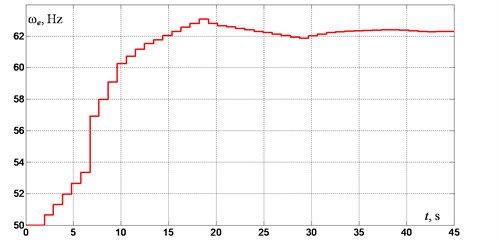
Fig. 3. Power supply frequency
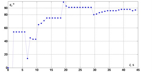
Fig. 4. Phase shift between oscillation of the system and excitation force
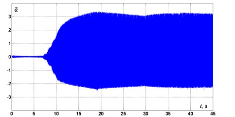
Fig. 5. Acceleration of platform oscillations
Experiments have shown that for other values of the initial frequency of the supply voltage starting from 45 Hz, the control system provides tuning to the required near-resonant mode. Moreover, the closer the initial frequency to the resonance, the less regulation time is required.
For initial frequencies less than 45 Hz the control system was unable to determine steady-state oscillations. That is due to violation of the relevant synchronization of unbalanced exciters as we move away from the resonance frequency corresponding to a purely vertical oscillations form. Furthermore, the duration of transient processes in the system also increases.
6. Conclusion
Experimental studies have shown that the proposed control algorithm affords for the system to tune from below-resonance oscillation mode to the near-resonant one with a predetermined phase shift value, with mass and stiffness parameters of the oscillating system being unknown initially. Regulation time significantly depends on the accuracy of measuring a phase shift as well as on value of damping , that is determined experimentally. It is found that the range of working frequencies of the control system is limited to a range where vertical oscillations dominate, which results from the possibility to determine a steady-state oscillation regime. To extend the operating frequency range it is necessary to improve the algorithms of determination of a steady-state oscillation regime and a phase shift value taking into account dynamic characteristics of a real vibrating machine.
References
-
Vibration in the Technique: Handbook. Vol. 4. Vibration Processes and Machines. Mechanical Engineering, Moscow, 1981.
-
Blekhman I. I. Synchronization in Science and Technology. ASME Press, New York, NY, USA, 1988.
-
Blekhman I. I., Fradkov A. L., Tomchina O. P., Bogdanov D. E. Self-synchronization and controlled synchronization: general definition and example design. Mathematics and Computers in Simulation, Vol. 58, Issues 4-6, 2002, p. 367-384.
-
Astashev V., Babitsky V., Vulfson I. Dynamics of Machines and Machine Control. Mechanical Engineering, Moscow, 1988.
-
Panovko G. Ya., Shokhin A. E., Eremeikin S. A. The control of the resonant mode of a vibrating machine that is driven by an asynchronous electro motor. Journal of Machinery Manufacture and Reliability, Vol. 44, Issue 2, 2015, p. 109-113.
-
Panovko G. Ya., Shokhin A. E., Barmina O. O., Gorbunov A. A. Method of Automatic Setting of Resonant Modes of Oscillations of Vibration Machine Driven by Induction Motor. RU Patent 2572657 C1, 2014.
About this article
The study was performed account for a grant of the Russian Science Foundation (Project No. 15-19-30026)).
