Abstract
The unbalance of rotating machines excites their lateral vibration that can become excessive in the vicinity of the critical speeds. Placing magnetorheological dampers to the rotor supports is a possible technological solution for reducing its amplitude. Both the analytical studies and practical experience show that behaviour of these damping elements is strongly nonlinear. A novel mathematical model of a magnetorheological squeeze film damper has been developed on the assumptions of the classical theory of lubrication, except that for the lubricant. The magnetorheological oil is represented by a bilinear material, the yielding shear stress of which depends on magnetic induction. The simulation results show that a right control of the damping force arrives at significant reduction of the vibration amplitude. The development and application of a new model of a magnetorheological squeeze film damper and confirmation of its efficiency and computational stability are the principal contributions of this article.
1. Introduction
The unbalance is a source of excitation of lateral vibration of rotors that becomes excessive if they operate near the critical speeds. An often used technological solution for its reducing consists in placing damping devices in the rotor supports. As discussed in [1], to achieve their optimum performance, their damping effect must be adaptable to the current operating conditions. For this purpose, several different types of controllable damping devices based on mechanical, hydraulic, and electromagnetic principles have been developed [2-6].
The enhanced mathematical models of a short and long squeeze film magnetorheological damper were presented by Zapomel et al. [7, 8]. These models utilize Bingham material to represent the magnetorheological oil.
In this paper, the presented model of a magnetorheological squeeze film damper is based on utilization of bilinear material. The model was implemented in the computational procedures for investigation of lateral vibration of flexible rotors. The aim of the analysis was to study efficiency of magnetorheological damping devices used for attenuation of lateral oscillations of rotors operating in the regime when they accelerate and run over the critical speeds.
The development of a novel model of a magnetorheological squeeze film damper, its implementation in the procedures for investigation of the steady state and transient vibrations of flexible rotors, and analysis of efficiency of the magnetorheological damping devices applied in the field of rotor dynamics are the principal contributions of this article.
2. Determination of the controllable hydraulic damping forces
The main parts of a squeeze film magnetorheological damper (Fig. 1) are two concentric rings between which there is a clearance filled with magnetorheological oil. The inner ring is coupled with the rotor journal by a rolling-element bearing and with the damper housing by a squirrel spring. The lateral vibration of the rotor squeezes the oil film, which produces the damping effect. The damper is equipped with electric coils generating magnetic flux that passes through the lubricating layer. As resistance against the flow of magnetorheological oils depends on magnetic induction, the change of the electric current changes the damping force.
The magnetorheological oils belong to the class of fluids with a yielding shear stress. It means the flow occurs only in those areas where the shear stress between two neighbouring layers exceeds a limit value. In the region, called a core, where the shear stress remains lower, the oil behaviour is similar to solid matters.
The developed model of a magnetorheological squeeze film damper is based on assumptions of the classical theory of lubrication except that for the lubricant. The magnetorheological oil is represented by a bilinear material, the yielding shear stress of which depends on magnetic induction. In addition, it is assumed that the geometry and the design of the damper make it possible to consider it as short.
On these conditions, the pressure distribution in the full oil film is described by the Reynolds equation adapted to bilinear material [9]:
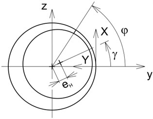
where stands for the pressure, is the pressure gradient in the axial direction, is the axial coordinate defining position in the oil film (Fig. 2), is the film thickness, is the width of the damper gap, is the rotor journal eccentricity, is the damper circumferential coordinate (Fig. 2), is the position angle of the line of centres (Fig. 2), is the yielding shear stress, is the shear stress at the core border, , are the dynamic viscosities of the oil inside and outside the core area respectively, and (.) denotes the first derivative with respect to time. is the axial coordinate specifying the location at which the core touches the rings surfaces. is the pressure gradient in the axial direction at location specified by axial coordinate .
Fig. 1Scheme of a magnetorheological squeeze film damper
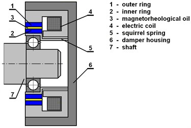
Fig. 2The damper coordinate systems
The Reynolds Eqs. (1-2) are referred to the extents of the axial coordinates and , respectively. denotes the damper axial length. More details on derivation and solving the Reynolds Eq. (1-2) can be found in [9].
In that part of the damper gap where the thickness of the oil film rises with time a cavitation takes place. In cavitated areas the Reynolds equation does not hold. In accordance with the observations, in the developed mathematical model it is assumed that the pressure of the medium in cavitated regions remains constant and equal to the pressure in the ambient space.
The and components of the hydraulic force , by which the oil film acts on the rotor journal are obtained by integration of the pressure distribution around the circumference and along the length of the damper:
where is the gap mean radius and is the pressure distribution in the damper clearance.
3. Modelling of the magnetic circuit
At the simplest distinguishing level, the damper housing can be considered as a body composed of a number of parallel branches mutually turned in the circumferential direction (Fig. 3). Each branch represents a divided core of an electromagnet with the gap filled with magnetorheological oil. Then magnetic induction in the damper gap at location specified by the angular coordinate can be expressed by means of a semi-analytical formula:
where is the design parameter, , are the vacuum and relative permeabilities of the magnetorheological fluid, respectively, and is the current.
Fig. 3One branch representing the damper housing
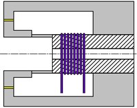
From the physical point of view, design parameter is a product of the number of the coil turns and magnetic efficiency.
Based on the carried-out experiments at different working places, the dependence of the yielding shear stress on magnetic induction can be approximated by a power function:
where and are the proportional and exponential material constants of the magnetorheological oil.
4. The investigated rotor system
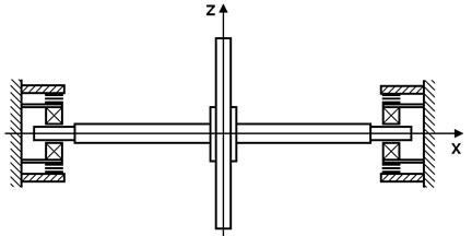
The rotor system (Fig. 4) that is a subject of investigations consists of a flexible shaft and of one rigid disc. At both its ends, the shaft is coupled with the frame by magnetorheological squeeze film dampers. The rotor turns at a variable speed and is loaded by its weight and by the disc unbalance. The squirrel springs of both dampers are prestressed to eliminate their deflection caused by the rotor weight. The whole system can be considered as symmetric relative to the disc middle plane.
Fig. 4Scheme of the studied rotor system
In the computational model, the rotor is represented by a flexibly supported Jeffcott one and both dampers by springs and nonlinear force couplings.
The lateral vibration of the rotor is described by the motion equation:
where , , are the mass, stiffness and circulation matrices, , are the matrices of external (environmental) and material (shaft material) damping, is the angular velocity of the rotor rotation, is the vector of displacements of the disc and the journal centres in the (horizontal) and (vertical) directions, , are the vectors of applied and hydraulic damping forces, and (..) denotes the second derivative with respect to time.
The Adams-Moulton direct integration (transient solutions) and the trigonometric collocation methods (steady state solution) were applied to solve the equation of motion Eq. (10).
5. Results of the simulations
The technological parameters of the studied system are: the disc mass of 250 kg, the shaft stiffness of 20.0 MN/m, the stiffness of each squirrel spring of 5.0 MN/m, the coefficient of the disc external damping of 10 Ns/m, the coefficient of the shaft material viscous damping of 0.00003 s, the damper gap middle radius of 800 μm, the oil dynamical viscosity (not effected by the magnetic field) of 0.3 Pas, the magnetorheological oil proportional and exponential material constants of 10000, 1.1, respectively.
The rotor turns at constant angular velocity of 150 rad/s. At the specified point of time, it starts to accelerate so that its speed increases uniformly to 250 rad/s during the span of time of 1.0 s. The task was to propose dependence of the applied current on time to minimize amplitude of the rotor vibrations during its passing over the critical speed.
A simple analysis gives the natural frequency of the rotor system of 163 rad/s. It implies the rotor must pass through the resonance area during its acceleration.
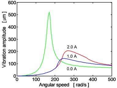
Fig. 5 shows the frequency response of the disc center (vibration in the horizontal direction) for three magnitudes of the applied current (0.0, 1.0, 2.0 A). If the rotor turns at angular speed lower than approximately 230 rad/s, the maximum reduction of the oscillation amplitude is achieved if the current is maximum. To achieve the same effect for higher operating velocities, the current must be minimum (0.0 A).
Fig. 5The disc center frequency response (direction y), current: 0.0 A, 1.0 A, 2.0 A
In Fig. 6, the time histories of the disc center displacement in the horizontal direction are depicted during running the rotor over the critical angular velocity for the case when the damping elements in the rotor supports work in the passive regime for two magnitudes of the electric current of 0.0 A, 2.0 A. The increase of the oscillation amplitude is significant especially if no current is applied. The observed behavior is in full correspondence with the frequency response characteristic (Fig. 5).
Fig. 6Time history of the disc center displacement (y direction), current 0.0 A, 2.0 A
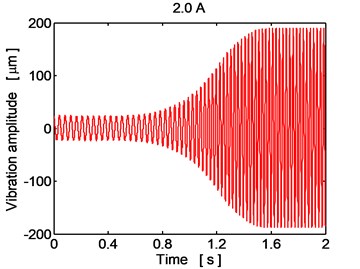
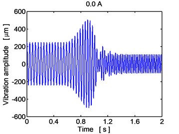
Fig. 7Time history of the disc center displacement (y direction), controlled current
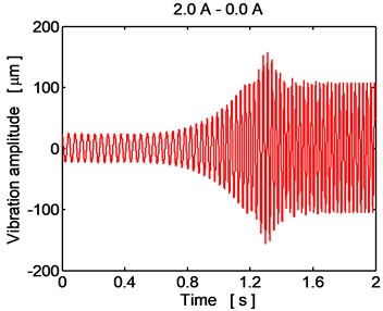
The optimum variant of reducing the rotor vibration during its acceleration consists in a gradual decrease of the electric current feeding the damper coils from 2.0 A to zero in the time interval from 600 to 900 ms after the point of time when the rotor starts to accelerate. As evident from Fig. 7, this operation minimizes the oscillation amplitude both during the transient period when the rotor passes through the resonance area and after finishing the rotor acceleration when its vibration becomes steady state.
6. Conclusions
This article presents a novel mathematical model of a magnetorheological squeeze film damper for reducing lateral oscillations of flexible rotors and its implementation in the computational procedures. The principle of work of this damping device is based on combination of several physical phenomena (mechanical, hydraulic, electrical, magnetic). Because of the hydraulic damping forces, the governing equations of the rotor have a strongly nonlinear character. The performed simulations showed that the developed procedures, which are based on modelling the magnetorheological oil by bilinear material, are computationally stable, confirmed that the right control of the applied current enables to minimize amplitude of the rotor vibrations in the vicinity of the critical speeds, and enabled the influence of magnetorheological damping devices on behaviour of flexible rotors to be learnt more on.
References
-
Zapoměl J., Ferfecki P., Kozánek J. Determination of the transient vibrations of a rigid rotor attenuated by a semiactive magnetorheological damping device by means of computational modelling. Applied and Computational Mechanics, Vol. 7, Issue 2, 2013, p. 223-234.
-
Mu C., Darling J., Burrows C. R. An appraisal of a proposed active squeeze film damper. Journal of Tribology, Vol. 113, Issue 4, 1991, p. 750-754.
-
El-Shafei A., El-Hakim M. Experimental investigation of adaptive control applied to HSFD supported rotors. Journal of Engineering for Gas Turbines and Power, Vol. 122, Issue 4, 2000, p. 685-692.
-
Takayama Y., Sueoka A., Kondou T. Modeling of moving-conductor type eddy current damper. Journal of System Design and Dynamics, Vol. 2, Issue 5, 2008, p. 1148-1159.
-
Morishita S., Mitsui J. Controllable squeeze film damper (an application of electro-rheological fluid). Journal of Vibration and Acoustics, Vol. 114, Issue 3, 1992, p. 354-357.
-
Wang J., Meng G. Magnetorheological fluid devices: principles, characteristics and applications in mechanical engineering. Proceedings of the Institution of Mechanical Engineers, Part L: Journal of Materials: Design and Applications, Vol. 215, Issue 3, 2001, p. 165-174.
-
Zapoměl J., Ferfecki P., Forte P. A computational investigation of the transient response of an unbalanced rigid rotor flexibly supported and damped by short magnetorheological squeeze film dampers. Smart Materials and Structures, Vol. 21, Issue 10, 2012, p. 1-12.
-
Zapoměl J., Ferfecki P. Mathematical modelling of a long squeeze film magnetorheological damper for rotor systems. Modelling and Optimization of Physical Systems, Vol. 9, 2010, p. 97-102.
-
Zapoměl J., Ferfecki P. 2015. A 2D mathematical model of a short magnetorheological squeeze film damper based on representing the lubricating oil by bilinear theoretical material. Proceedings of the IFToMM World Congress, Taipei, Taiwan, 2015, p. 1-6.
About this article
The research work reported in this article was made possible by the Projects 15-06621S (Czech Science Foundation) and LQ1602 (IT4Innovations Excellence in Science). The support is highly acknowledged.
