Abstract
This paper presents complex strategy for a development of highly elastic couplings. There are presented methods how to determine the dynamics characteristic of the coupling. The highly elastic coupling is applied to the connection of an in-line six-cylinder natural gas engine and an electrical generator. Loading forces are applied based on the values of combustion pressures measured in an engine cylinder. Experimental verification of the computational model results was carried out by measuring the values on a testing engine using non-contact laser measuring technique.
1. Introduction
Modern cogeneration units (CU), based on internal combustion engines (ICE), are developed as highly efficient systems which transfer primary source like compressed natural gas (CNG) or electricity and heat. There are many areas of application, namely hotels, social service buildings, hospitals, clinics, aqua parks, fitness centres, schools, office buildings, or supermarkets. ICE, electric generator and the couplings are fundamental subsystems of CU. The CUs are, generally, designed with long service life and the main components have to fulfil this requirement as well. Elastic coupling of any type is a crucial component, in regard to vibrations and of course strength of CU subsystems.
In general, vibrational problems are solved using two basic, the experimental or computational methods. Experimental methods are often very expensive and therefore rapid developments of modern computational methods with highly specialized computational models are in demand. Full description of computational models presents Novotny [1, 2].
Fig. 1Highly flexible coupling used for connection of ICE and electric generator
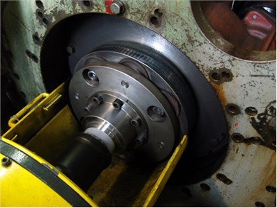
In general, an engine-generator coupling is an important component of CU. It can significantly decrease system loading together with a decrease of NVH. The mechanical properties of the rubber element can be characterized by a very low compressibility and a high ability to reach large strains at low stress without any plastic deformations. Force versus deformation of rubber element is nonlinear temperature and frequency dependent.
PIVKO highly elastic, self-supporting and high-speed couplings can be used to build flexible shafts. The basic coupling comprises of a steel coupling body, elastic elements, centralising sleeves, hubs and/or flanges. Elastic elements are pressed into the bores and centralising sleeves are pushed inside the elements, the elements can be pre-compressed by this method. The elements could have hardness between 50-80 Shore, usually the hardness of 65 Shore for temperatures –40 to +80 °C and the corresponding chemical resistance. Couplings can suppress torsional oscillations and thereby significantly extending the life of the drive. Elastic elements are easily replaceable due to the design and do not require disassembly of the CU. In most cases the coupling body elements and sleeves could be removed radially for an overhole. The elements are replaced whilst sleeves can be re-used. Example of such a coupling is presented in Fig. 1. More information can be found in [3].
2. Determination of static characteristics of rubber element
Rubber element characteristics are analysed separately by technical experiments (see Fig. 2) and computational models (see Fig. 3). Later the coupling characteristics are derivate. Static deformation characteristics of rubber element assume the following components:
• Displacement in the radial direction (corresponding to the load of the element perpendicular to the axis of the element).
• Displacement in the axial direction (corresponding to the load of the element in the axis of the element).
• Angular displacement perpendicular to the axis of the element (corresponding to the moment perpendicular to the axis of the element).
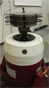
A determination of the static characteristic of the rubber element is made on a universal testing machine.
Fig. 2Arrangement of technical experiment for a determination of static characteristic of a) rubber element and b) detail of test sample
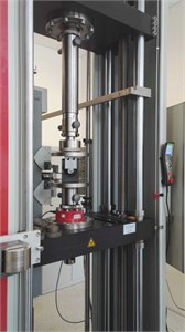
a)
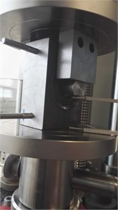
b)
A determination of these components is carried out using computationally – experimental procedure, where the calculation model is tuned based on elementary technical experiments.
The computational determination of the static characteristics of the rubber element consists in entering the displacement in a given direction and evaluation of the overall force required for implementation of the displacement.
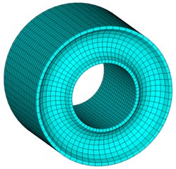
Computational determination of the properties of rubber element is performed using the finite element method (FEM). Mooney-Rivlin two-parameter model is used as rubber material model. Material constants characterizing the deformation of the deviatoric stress are 1.11 and 0.27 and incompressibility parameter is 0.018.
Fig. 3FE model of rubber element
3. Determination of coupling dynamic characteristic
An arrangement of technical experiment for the determination of the dynamic characteristic of rubber element is presented in Fig. 4.
Fig. 4Arrangement of technical experiment for a determination of the dynamic characteristic of rubber element
The technical experiment is carried out in above-resonance area of the system consisting of the rubber element and a seismic mass. The following parameters are evaluated dynamic stiffness and relative damping .
The resulting static torsional stiffness of whole coupling can be calculated as follows:
where are pitch diameter of rubber elements, is a number of elements on one side and is a total number of rubber elements.
Frequency range from 50 Hz to 350 Hz and different temperatures have been used for a determination of dynamic characteristic of rubber element, respectively whole coupling.
The resulting dependency of coupling dynamic stiffness on the loading frequency and element temperature can be written as:
where is static coupling stiffness at temperature of 25 °C, is frequency correction coefficient and is temperature correction coefficient for stiffness.
Relation of viscous damping coefficient , relative damping and frequency is according to equation:
Relative damping dependence on temperature can be expressed as:
where is relative damping at temperature of 25 °C and is temperature correction coefficient for damping.
It is supposed that the dependence of relative damping on the loading frequency is minimal and therefore the frequency dependence is not included in the correction relationships.
4. Simulation of engine-electric generator coupling
Computational model for a solution of system vibration is based on multibody system and comprises of two subsystems:
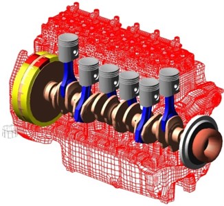
• Virtual cranktrain including all the significant components of cranktrain (see Fig. 5).
• Computational model of highly elastic coupling including frequency and temperature dependencies.
The advanced computational model is solved in time domain. This enables to incorporate different physical problems, including various nonlinearities. The model is assembled, as well as, numerically solved in MBS ADAMS. ADAMS is a general code and enables an integration of user-defined models directly using ADAMS commands or using user written FORTRAN or C++ subroutines. Full description of cranktrain computational models can be found in [1].
Fig. 5Virtual cranktrain assembled in multibody system
The computational model of highly elastic coupling comprises of three discs connected by nonlinear spring-damper systems, depending on a number of rubber elements. In general, rubber element stiffness and damping members are frequency independent but connected together are frequency dependent. Geometrical nonlinearities and pretension stresses of the rubber element are also considered.
The computational model is forced by gas forces in combustion chambers considering operational states of the ICE.
5. Results
The vibrational results are presented on a turbocharged six-cylinder engine using CNG as fuel. The main engine parameters are: engine displacement 11.9 litres and peak power output 250 kW at engine speed 1800 rpm.
Fig. 6Measurement of crankshaft pulley angular vibrations
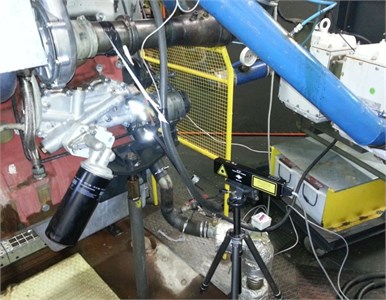
Technical experiments (see Fig. 6) are proposed to verify final design of highly elastic coupling, as well as to validate computational models. There are two operational states considered:
State of maximal load for engine speed 1000-2000 min-1.
Starting state for engine speed 200-900 min-1.
Fig. 7Dominant harmonic orders vs. engine speed for computed (“Comp.”) and measured (“Exp.”) angular displacements
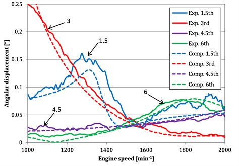
Dominant harmonic orders vs. engine speed for computed and measured angular displacements are presented in Fig. 7. The 3rd harmonic order is closely connected with vibration of ICE and the engine brake mechanical system. The coupling is always designed to avoid resonances in operational engine speeds.
The results show torsional resonance of the 3rd order near the engine speed 520 min-1, this engine speed is highly critical for the CU, there are no operational speeds designed. The operational speeds show no resonances and the coupling is designed correctly.
6. Conclusions
Experimental and computational results verified the final coupling design for proposed operational conditions of the target engine and electric generator system. The torsional resonance of the 3rd order lies far away from the operational speed and the coupling design is confirmed.
References
-
Novotny P. Virtual Engine – A Tool for Powertrain Development. Habilitation Thesis, Brno University of Technology, Brno, 2009.
-
Novotný P., Prokop A., Zubík M., Řehák K. Investigating the influence of computational model complexity on noise and vibration modeling of powertrain. Journal of Vibroengineering, Vol. 18, Issue 1, 2016, p. 378-393.
-
Kocian I. PIVKO Spojky Brzdy Hřídele. http://www.pivkobrakes.com/, 2016.
About this article
The research leading to these results has received funding from the Ministry of Education, Youth and Sports under the National Sustainability Programme I. (Project LO1202) and with help of the Project FSI-S-11-8 granted by specific University Research of Brno University of Technology. The authors gratefully acknowledge this support.
