Abstract
Owing to the complex working conditions, large load changes and inertia of variable pump, pressure shock seriously lowers the efficiency, stability and accuracy of pump-controlled hydraulic steering system. To study the pressure shock characteristics, a physical model of pump-controlled hydraulic steering system was deduced first, and the system dynamic characteristics were simulated by MATLAB/SIMULINK; then the AMESim model was also established to analyze the shock pressure further. By comparison with the simulation results in SIMULINK, the validity of AMESim model is verified. Based on AMESim model, the influence of the navigation speed, spring stiffness of feedback mechanism and rudder angular velocity to the shock characteristics were analyzed specially. According to the results, the design and control methods to reduce hydraulic shock are obtained, which provide a theoretical basis for improving the characteristics of pump-controlled rudder.
1. Introduction
Pump-controlled hydraulic steering system is the key link maintaining the course stability and maneuverability for ship. Steering system generally adopts a closed cycle system supplied by variable plunger pump to control the rudder. The noise caused by pressure shock from the variable pump’s high-pressure chamber and low-pressure chamber alternately changing [1], not only affects the work and rest of crew, but also causes damages to pipeline and equipment. Especially for naval ships, it harms the concealment seriously. Therefore, it is very necessary to develop an effective scheme for reducing pressure shock through theoretical analysis and simulation of pump-controlled hydraulic steering system. In this aspect, Gu Bangzhong, Ma Chao, Yu Qiuhui proposed some optimization methods and measures [2-4] to reduce pressure shock by study on mechanism analysis and engineering calculation of hydraulic shock and vibration. Wright R. E. concluded that the shock velocity is related to the pipe diameter, wall thickness and elastic modulus of hydraulic oil [5]. Fu Yongling established proportional valve-controlled steering system model and concluded that the optimal control output of current could reduce reversing shock [6]; Yu Wubin established the mathematical model of pump-controlled hydraulic steering servo system and studied the influence of dynamic pressure damping calibrating methods and parameters [7]. Xu Xingzhi analyzed the flutter performance of hydraulic rudder’s circuit system for the dynamic stiffness [8]. However, the research on shock pressure of pump-controlled hydraulic steering system is still relatively rare.
In this paper, the pressure shock simulation was carried on and the dynamic properties were analyzed in AMESim, which provides basis for optimizing the hydraulic system and reducing the noise.
2. Principle of pump-controlled hydraulic steering system
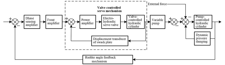
Pump-controlled hydraulic steering system mainly consists of pump-controlled device, circuit conversion system, hydraulic steering engine, hydraulic damper, rudder angle feedback mechanism and etc. The principle block diagram of the control system is shown in Fig. 1. By the phase sensing, the front and the power amplifier, the signal of the rudder angle input is converted into a voltage signal to control the spool displacement of the electro-hydraulic servo valve. Then the valve port is opened and the hydraulic flow moves the piston rod of the valve-controlled hydraulic cylinder. At the same time, displacement signal of the piston rod is proportionally transformed into angle signal of swash plate that controls the flow of variable pump and pump-controlled cylinder to output. Finally, the signal of rudder angle is fed back to form a closed loop system to realize the control of rudder angle.
Fig. 1Principle block diagram of pump-controlled hydraulic steering system
3. Mathematic model of pump-controlled hydraulic steering system
3.1. Mathematic model of axial plunger pump
The flow equation of axial plunger pump is:
where is outflow of pump, is distribution circle diameter of the plunger in cylinder, is diameter of plunger, is pump’s swash plate angle, is pump revolving speed, is plunger number in plunger pump, is the volume efficiency of plunger pump.
3.2. Mathematic model of the pump-controlled hydraulic cylinder
(1) The force equilibrium equation of hydraulic cylinder is:
where and are respectively the pressures of high-pressure pipe and low-pressure pipe in the hydraulic system, is equivalent mass including the mass of hydraulic piston and moving parts, is the hydraulic oil damping of hydraulic cylinder, is load on piston, is effective area of the piston in hydraulic cylinder, is stiffness of load.
(2) The continuity equation of high pressure chamber flow in hydraulic cylinder is:
where , and are respectively the coefficients of leakage inside and outside hydraulic cylinder, and are respectively the total volume and the initial volume of working chamber of the pump and the hydraulic cylinder and the connecting pipe, is hydraulic oil elasticity modulus.
3.3. Mathematic model of hydraulic cylinder load
The normal force on the rudder plate at sea is:
where is rudder angle, is the lateral projection area of control vanes, is navigational speed.
3.4. Modeling valve-controlled servo mechanism
For the convenience of research, the valve-controlled servo cylinder is regarded as a symmetrical cylinder controlled by a three-position four-way valve [9]. And also define some assumptions as follows: (1) The oil-supply pressure is constant and the oil-return pressure is ; (2) The four throttle windows of the valve are matching and symmetry; the rectangular window is used; the inlet flow of the valve is turbulent flow; (3) The pipe loss and dynamic state is regardless; the temperature and density are constant.
is the oil-inlet flow of the high-pressure chamber, is the oil-return flow of the low-pressure chamber. And the equation [10]is:
where is flow coefficient of valve port, is area gradient of spool, is diameter of spool, is oil-feed pressure, is the pressure of high-pressure chamber, is the hydraulic oil density, is the displacement of spool.
Regardless of hydraulic oil elasticity modulus, the flow continuity equation in the high-pressure chamber is:
where and are respectively the coefficients of leakage inside and outside hydraulic cylinder, is the pressure of low-pressure chamber, is piston area of servo cylinder, is piston displacement of servo cylinder.
3.5. SIMULINK simulation results and analysis
According to the principle block diagram, by combining the Eqs. (1) to (7), SIMULINK model of pump-controlled hydraulic steering system is obtained and its parameters are confirmed, and then the SIMULINK model is simulated.
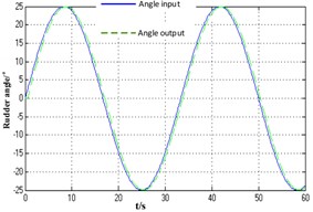
The signal of the steering angle input is: . Where , the speed of the steering angle input is 2°/s, the navigational speed is 6 knots. The change of rudder angle and speed of the hydraulic cylinder is shown in Fig. 2 and Fig. 3.
Fig. 2Speed of hydraulic cylinder
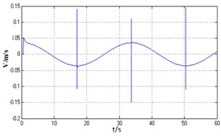
Fig. 3Rudder angle
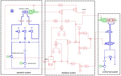
4. Establishment of steering system of AMESim model
The parameters of AMESim model are set according to the actual situation. The system model built by connecting each component with hydraulic pipes is shown in Fig. 4.
For accurately simulating shock wave in pipes and oil compression, the expansion of pipe is taken into account, and model HL04 is selected and properties including Young's modulus, wall thickness and bulk modulus are set.
Fig. 4AMESim model of pump-controlled steering system
5. Factors influencing pressure shock
To study the factors influencing system’s pressure shock further, by using AMESim model of pump-controlled hydraulic steering system, simulation results are obtained and analyzed through changing navigation speed, spring elasticity coefficient of valve-controlled hydraulic cylinder in the servo control system and the rudder angle velocity.
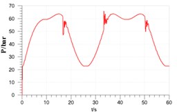
By comparing Figs. 5-7 with Figs. 2-3, it can be found the two dynamic characteristics are basically coincident. And by analyzing figures, it shows that: maximum response delay between rudder angle input and actual rudder angle is 0.8s, amplitude attenuation is less than 3 % , and the system is stable; piston speed jumps when rudder angle reverses, and the biggest fluctuation jump ranges from –0.13 m/s to 0.14 m/s, and after passing the reversing point velocity tends to be stable; in hydraulic cylinder maximum pressure fluctuation is 18 bar which is about 28 % of system working pressure when rudder reverses. According to Eq. (2), when rudder angle changes oppositely, load force F of rudder plate is still in line with the former, which makes original resistance translate into the change of power, speed and pressure.
Fig. 5Piston displacement
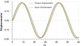
Fig. 6Piston speed
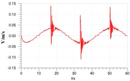
Fig. 7Pressure of cylinder chamber
5.1. Influence of speed change on pressure shock
In Fig. 8, it shows that the speed will change along with the actual complex conditions. Keeping the rudder angle input of 2°/s and setting the spring elasticity coefficient of the pressure spring in the hydraulic cylinder of the feedback mechanism to 10 N/mm, and then the high-pressure chamber’s pressure curves at the different navigational speed of 6 knots, 10 knots and 14 knots are obtained (speed curve is omitted).
Analysis shows that: when the navigational speed changes from 6 knots to 14 knots, the velocity jump of piston increases from 0.27 m/s to 1.2 m/s in the reverse; the working pressure’s peak value of chamber B increases from 65 bar to 230 bar, and the shake in the reverse strengthen, and the duration time changes from 2 s to 4 s, and the pressure jump changes from 18 bar to 110 bar, namely the percentage of working pressure by 28 % increased to 48 %. Therefore, in order to make the steering system stable, the appropriate navigational speed should be selected to reduce the hydraulic shock under the condition of satisfying the navigation requirements.
Fig. 8Pressure of cylinder chamber
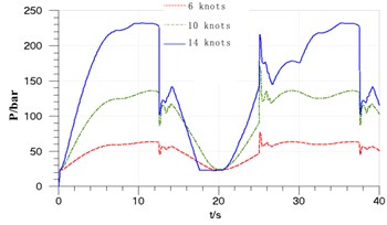
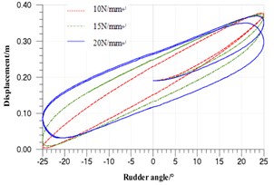
Fig. 9Piston displacement-rubber angle
5.2. Effect of the feedback mechanism
Keeping the navigational speed of 14 knots and the rudder angle input of 2°/s, in the feedback mechanism, the hydraulic cylinder’s displacement-rudder angle input curves at the different spring elasticity coefficients of 10 N/mm, 15 N/mm, 20 N/mm of the pressure spring are shown in Fig. 9 (the pressure curve of the high-pressure chamber is omitted).
From the simulation results, when the signal input and the navigational speed are under the constant circumstances, with the increase of the spring’s elastic coefficient (namely feedback is weakened), the linear degree of the displacement and angular displacement will reduce, and the tracking error will increase, and the system accuracy will decrease. Due to the asymmetry of the hydraulic cylinder, the return curve does not coincide with the push curve. With the decrease of the spring elasticity, the pressure shake in the reverse enhances, and the reverse shock increases.
From the above analysis, enhancing system’s feedback will improve the linear relationship between the displacement and the angular displacement and the accuracy of the system. But at the same time it will enhance system shake, increase the reverse shock and reduce the system stability. Therefore, when the elastic coefficient of spring is set, the actual situation of the whole system should be taken into consideration to make the system optimal.
5.3. Effect of the input rudder angle velocity
Keeping navigational speed of 14 knots and setting spring elasticity coefficient of pressure spring in hydraulic cylinder of the feedback mechanism to 10 N/mm, the simulation curves with the different rudder angle input of 2°/s, 3°/s, 4°/s are shown in Fig. 10, Fig. 11 and Fig. 12. In Fig. 12, the curves 1-6 are respectively representative of the cylinder displacement signals of 2°/s input and output, 3°/s input and output, 4°/s input and output.
Fig. 10Pressure of cylinder chamber
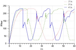
Fig. 11Piston speed
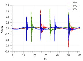
In Fig. 10-13, it shows that when the input rudder angle speed from 2°/s to 4°/s, the system’s maximum response delay will change from about 0.6 s to 1.8 s, and the signal amplitude attenuation will increase from 2 % to 10 %. With the rudder speed increasing, the piston’s speed jump in the reverse will change from –0.4 m/s to +0.4 m/s to –0.65 m/s to +0.67 m/s and the jump peak and scope will enlarge; the maximum pressure pulsation increases from about 35 bar to 120 bar, and the shock pressure will enlarge with the increase of the rudder angle. So the selection of the rudder angle velocity should be appropriate, and the input rudder speed should be set reasonably in combination with the actual requirements, and the accuracy and stability of the system should be also considered.
Fig. 12Piston displacement
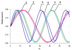
Fig. 13Pressure of cylinder chamber
6. Conclusions
(1) In pump-controlled hydraulic steering system, when rudder angle is reversing, the hydraulic cylinder piston’s velocity and pressure shock become greater, and there exists an obvious pressure shock;
(2) If the system response frequency is high, it leads that the system tracking performance is not very ideal and the input and output rudder angle has a certain delay and attenuation;
(3) Proper system operation conditions, such as input rudder angle speed, system feedback ratio and navigational speed, can change the system load evenly and reduce pressure shock.
References
-
Ramamoorthy Sripriya, Groshb Karl, Dodson John M. A theoretical study of structural acoustic silencers for hydraulic systems. Acoustical Society of America, Vol. 111, Issue 5, 2002, p. 2097-2108.
-
Gu Bangzhong Analysis of the hydraulic shock of ship steering system. China Shiprepair, Vol. 1, 2005, p. 26-28.
-
Ma Chao Causes and countermeasures of hydraulic shock. Heilongjiang Science and Technology Information, Vol. 21, 2007, p. 45-48.
-
Yu Qiuhui, Chen Jian Optimization design and modal test of fixtures for vibration testing. Noise and Vibration Control, Vol. 6, 2010, p. 70-74.
-
Wright R. E. Mitigating damage by hydraulic transients in liquid pipeline systems. IEEE Petroleum and Chemical Industry Conference, 1993, p. 147-149.
-
Fu Yongling, Zhao Ke Modeling and reducing of water hammer of proportional direction valve controlled ship steering system based on AMESim. Journal of Beijing University of Aeronautics and Astronautics, Vol. 36, Issue 6, 2010, p. 6-8.
-
Yu Wubin, Huang Yanong Dynamic analysis and simulation of submarine pump-controlled hydraulic steering servo system. Ship Science and Technology, Vol. 6, 1998, p. 47-51.
-
Xu Xingzhi, Gao Yagui, Zhang Weiguo Structural nonlinear flutter characteristics analysis for actuator-fin system with dynamic stiffness. Chinese Journal of Aeronautics, Vol. 24, Issue 5, 2011, p. 590-599.
-
Guo Bo, Li Yugui, Han Heyong Analysis of asymmetric valve control asymmetric cylinder system of hydraulic leveler. Advances in rolling equipment and technologies. Advanced Materials Research, Vol. 145, 2010, p. 477-480.
-
Sun Lingtong Modeling and Control of a Hydraulic System with Multi-Actuators. Purdue University, 2012.
About this article
