Abstract
The application of the piezoelectric materials in the engineering domains knows a great progress last years. The so-called smart structures are obtained essentially with these materials, whose gives to these structures an ability to attenuate noises and vibrations. In this paper we consider a piezoelectric bimorph plate with specific forms of electrodes on its top and bottom free faces.
1. Introduction
Both application of piezoelectric materials in the actuation field and related research have increased last years. This is due to their small size and their light weight. J. H. Yang and P. J. Zhang [1], studied the governing equations of nonlinear bending for piezoelectric cylindrical shell reinforced with BNNTs under combined electro-thermo-mechanical loadings, the following conclusions were drawn. The deflection and bending moment of the shell in linear case is greater than that in nonlinear case, applying positive and negative voltage to BNNT leads to increase and decrease of the deflection and bending moment. Moreover, T. Nestorović, S. Shabadi, D. Marinković and M. Trajkov [2] implemented a nine node piezoelectric shell element in commercial FE software ABAQUS which developed in [3]. In comparison with their previous work [4], the application has been extended to modelling of arbitrary thin walled structures also with complex geometries. Furthermore, E. Carrera and S. Brischetto [5] gives a static analysis of multilayer shells with embedded piezoelectric materials. They used the Reissner Mixed Variational Theorem to obtain transverse electromechanical variables (transverse shear and normal stresses, plus normal electrical displacement). The results obtained demonstrate the superiority of the proposed approach with respect to the other formulations considered, and its ability to furnish a priori interlaminar continuous transverse electrical displacement.
In addition, A. Zemirline, M. Ouali and A. Mahieddine [6] take into account the First Order Shear Deformation Theory to study the dynamic behavior of a bimorph beam. A delamination zone between the upper and the lower layer has been taken into consideration; the beam is discretised using the finite elements method. Several parameters are taken into consideration like structural damping, the geometry, the load nature and the configurations of the boundary conditions. Results show that the delamination between the upper and the lower layer affects considerably the actuation. A. Zemirline, M. Ouali and A. Mahieddine [7] the first-order shear deformation theory is used to study the static behavior of a piezoelectric bimorph beam with delamination between its layers, which is taken with several lengths and locations along the beam with different boundary conditions. It seen that the shape of the axial displacement field is not affected by either the length of the debonded zone or the variation in the ambient. However, this shape is deformed when an electrical field is applied.
In this work a piezoelectric bimorph plate in series configuration is taken into a consideration to study the influence of the electrode shape on its response, the plate is subjected to an electrical load. The set of equations is solved using the finite element method with Ansys software.
2. Mathematical formulation
Let us consider a piezoelectric bimorph plate, made of tow piezoelectric PVDF layers, the layers are perfectly bonded. The plate is considered in clamped-free boundary condition as presented in Fig. 1. To study the effect of the electrode shape on the plate response, a full square, a holed square, a full circular and a holed circular shape are treated.
The mathematical relationship reflecting the piezoelectric effect neglecting the effect of the temperature is given by Eq. (1) [6-8]:
were, the superscript denote the transpose of the matrix.
The deformation energy is given by Eq. (2) [6, 7]:
After several mathematical considerations the final form of the deformation energy will be written in Eq. (3) relating to the elastic, the piezoelectric and the dielectric term:
were, strain, stress, dielectric displacement, piezoelectric coefficients, elastic modulus, permittivity, electric field and the domain volume.
Using the SOLID226 element, provided by ANSYS which assume the piezoelectric effect [9], the plate is modelled. The geometry of this element is shown in Fig. 1.
Fig. 1Geometric configuration of the SOLID226 element [9]
![Geometric configuration of the SOLID226 element [9]](https://static-01.extrica.com/articles/17373/17373-img1.jpg)
3. Numerical modelling
To make a comparison between the effects of the electrodes on the plate response, the electrodes shapes are shown in Fig. 2.
All the electrodes are located in the middle of the plate, and they have the same surface which is calculated according to the width of the plate.
Meshing the plate in all cases gives the Fig. 3.
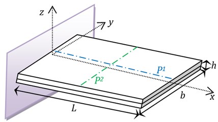
The geometrical parameters and the boundary conditions are shown in Fig. 4.
Fig. 2Electrodes configurations
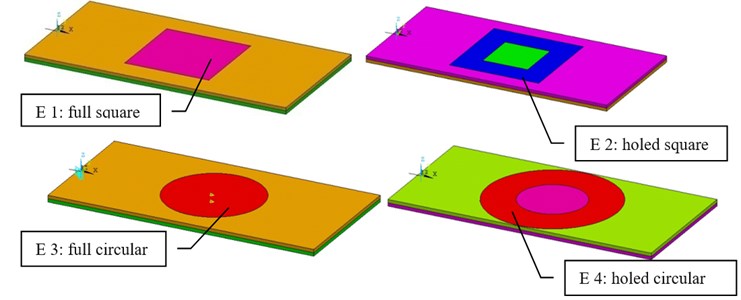
Fig. 3Meshed plates
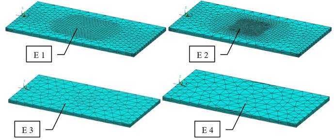
Fig. 4Geometrical parameters of the plate
4. Results
Considering the PVDF physical parameters listed in Table 1. The plate is subjected to the same electrical potential applied, which is 100 V on the top electrode and 0 V on the bottom.
and are the top and bottom thicknesses. and (in Fig. 4) are two paths which are uses to plot the obtained results.
The superposition of the results obtained by considering the two paths ( and shown in the Fig. 4) is illustrated on the Fig. 9 (for path ) and on Fig. 10 (for path ).
Table 1Physical and geometrical parameters
2e9 | N.m-2 | 2e-1 | m | ||
2e9 | N.m-2 | 5e-2 | m | ||
7.75e8 | N.m-2 | 5e-3 | m | ||
0.29 | 25e-4 | m | |||
2.2e-11 | C.N-1 | 25e-4 | m | ||
1.62e-11 | F.m-1 | ||||
1.62e-11 | F.m-1 | ||||
1.62e-11 | F.m-1 |
Fig. 5Vertical displacement of the plate in E1 configuration
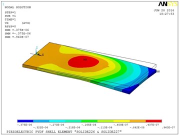
Fig. 6Vertical displacement of the plate in E2 configuration

Fig. 7Vertical displacement of the plate in E3 configuration

Fig. 8Vertical displacement of the plate in E4 configuration
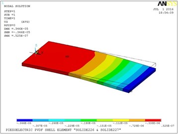
Fig. 9Vertical displacement in the width of the plate in the P2 path
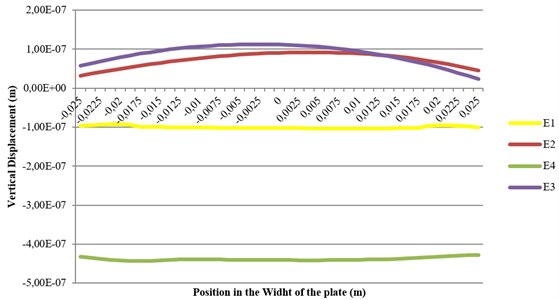
Fig. 10Vertical displacement in the length of the plate in the P1 path
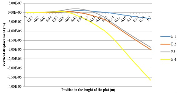
The holed circular electrode produces more actuation than the other electrodes studied, due to the distribution of the electric field within the area of the plate. The middle of the plate bends in the negative direction when the full electrodes (both circular and square) are used. The plate takes a different shape when voltage is applied in the fully square electrode configuration.
5. Conclusions
A piezoelectric bimorph plate in series configuration is taken into a consideration to study the influence of the electrode shape on its response; the plate is subjected to an electrical load. The set of equations is solved using the finite element method with Ansys software.
The bending moment is more important when the electrode is larger (for the same area, using a different shape can produce more actuation).
References
-
Yang J. H., Zhang P. J. Nonlinear bending of piezoelectric cylindrical shell reinforced with BNNTs under electro-thermo-mechanical loadings. Materials Sciences and Applications, Vol. 6, 2015, p. 743-752.
-
Nestorović T., Shabadi S., Marinković D., Trajkov M. Modeling of piezoelectric smart structures by implementation of a user defined shell finite element. Facta Universitatis, Series: Mechanical Engineering, Vol. 11, Issue 1, 2013, p. 1-12.
-
Marinković D. A new finite composite shell element for piezoelectric active structures. Fortschritt-Berichte VDI, Vol. 20, Issue 406, 2007.
-
Nestorović T., Marinković D., Chandrashekar G., Marinković Z. and Trajkov M. Implementation of a user defined piezoelectric shell element of analysis of active structures. Finite Elements in Analysis and Design, Vol. 52, 2012, p. 11-22.
-
Carrera E., Brischetto S. Piezoelectric shell theories with a priori continuous transverse electromechanical variables. Journal of Mechanics of Materials and Structures, Vol. 2, Issue 2, 2007, p. 377-399.
-
Zemirline A., Ouali M., Mahieddine A. Dynamic behavior of piezoelectric bimorph beams with a delamination zone. Steel and Composite Structures, Vol. 19, Issue 3, 2015, p. 759-776.
-
Zemirline A., Ouali M., Mahieddine A. Study of the delamination in the case of piezoelectric bimorph beams “static behavior”. Arab Journal of Science and Engineering, Vol. 40, 2015, p. 2747-2761.
-
Ansys 12 Help, Theory Reference Guide, Coupling, Piezoelectrics.
-
Ansys 12 Help, Element Reference Guide, Element Library, SOLID226.
About this article
