Abstract
Piezoelectric actuators (PEA) act an important role in active vibration control area due to the advantages of fast response, high output force, small size and light weight. A 6-axis orthogonal vibration isolation platform based on PEAs is designed, which satisfies the demands of heavy payload, small installation space and multi degree of freedom vibration isolation. The dynamic model of the six-axis orthogonal vibration isolation platform with PEAs is established using Newton-Euler method. With the layout of six PEAs around the axis of symmetry, the dynamic equations could be decoupled into two single-input-single-output (SISO) subsystems and two multi-input-multi-output (MIMO) subsystems. Based on the modal superposition method, the two MIMO subsystems are further decoupled. The control strategy for each SISO system is developed with LQR control method. To evaluate the effectiveness of the control method, the simulation and verification experiment are conducted. The simulation result and experimental data indicate that the decoupling control of the proposed six-axis orthogonal vibration isolation platform with piezoelectric actuators effectively reduces the vibration response of payload within the target frequency range of 20 Hz to 200 Hz.
1. Introduction
High resolution equipment and sensitive instruments taken by spacecraft or satellites require really quiet environment [1-4]. The performance of these facilities will be significantly reduced because of the perturbation generated by rotating machineries and compliant mechanisms, such as control moment gyroscope, reaction flywheel and solar wing [5-7]. A common way to deal with this problem is adding vibration isolation system between the vibration source and the precision devices [8-11]. Vibration isolation platform is usually applied because of compact structure and good capability of multi-degree-of-freedom vibration isolation. Nowadays, the passive, semi-active, active are generally applied in platform structure [9, 11-14].
Passive isolator is designed for certain system to achieve optimum isolation property, which owns the characteristic of high reliability, high stability and good high-frequency vibration isolation performance. However, the parameters of passive isolator are unchangeable after designed, which means it may not performs well when the property of control object alters. And furthermore, low-frequency vibration isolation effect is bad [15].
Semi-active vibration isolation technique using magnetorheological fluids, electrorheological fluids and some other smart materials can partly overcome the disadvantages of poor adaptability of passive vibration isolation. The damping coefficient or stiffness coefficient varies with the changing of motion state of control object. However, the low-frequency vibration isolation performance still needs to be improved [16].
Active vibration isolation systems own good low-frequency vibration isolation ability by using sensors and actuators based on different control methods [17]. So far, there have been many researches on actuators and control strategies, which are the core component of active vibration control platforms. Six-axis active vibration isolation platforms can be divided into soft platforms and stiff platforms according to the stiffness of actuators [18]. The resonant frequencies of soft platforms are generally very low, which significantly decrease the burden of control system in the low-frequency band. However, the output forces are usually small. So, they are not suitable for heavy payload vibration control [12, 19, 20]. Actuators used in stiff platforms have the properties of high stiffness and big output force, such as DC motors, magnetostrictive actuators and piezoelectric actuators (PEAs). In comparison, PEAs have been more widely investigated and applied in stiff platforms, because of the advantages of fast response, high output force, high stability, small size and light weight. Lots of platforms based on PEAs have been proposed, such as SEPTRA platform, MAIS platform and ULB piezoelectric Stewart platform [14, 21, 22]. The PEAs are set between the moving base and up-platform. Each PEA transfers the vibration energy from base to up-platform and generates control force under some certain control strategies to make the up-platform stable at the same time. Generally, the Stewart platform is a coupled system, which is difficult to establish controller. There are mainly two methods to deal with this problem [23-26]. One way is configuration design, which simplifies the dynamic behavior of Stewart platform by changing the layouts of actuators, such as the cubic Stewart platform. The other way is control method design, which decouples the dynamic equation of Stewart platform into sets of generalized single-degree-of-freedom subsystem and establishes a SISO controller for each subsystem. Generally, the algorism is very complicated and has to be changed if the configuration of Stewart platform altered.
In this paper, a Stewart platform employs PEAs with symmetric structure is designed to fit the demands of heavy load, large diameter and small installation size. The dynamic model platform with PEAs is established using Newton-Euler method and proven to be able to be decoupled under the proposed conditions. By applying modal superposition method, six SISO subsystems are obtained. Then LQR controller is designed for each SISO system. The verification experiment is conducted to evaluate the effectiveness of the control method. The experimental data indicates the decoupling control of the six-axis orthogonal vibration isolation platform with piezoelectric actuators is effective with the frequency of excitation during the frequency range of 20 Hz to 200 Hz.
2. Design and dynamic modeling of the platform
2.1. Design of the platform
A Stewart platform is proposed based on general cubic Stewart platform as shown in Fig. 1(a). In general, cubic Stewart platform, the actuators are parallel or perpendicular to each other. The extension cords of two adjacent actuators focus on up-platform or base. However, the diameter of the payload in this paper is 3.4 m, while the installation space is restricted under 0.1 m, which means there is not enough space to apply the general cubic Stewart platform for the research topic. Therefore, the up-platform is lowered down and the base is lifted up to cut the legs apart. The up-platform is connected to the base by six legs arranged evenly around the axis of symmetry via spherical joints. The prototype of proposed platform is shown in Fig. 1(b). The supporting legs are connected between two rigid plates to enhance assembly performance of platform and reduce the processing difficulty. Each leg is mainly composed of a PEA and an acceleration sensor. The payload, which is a cylinder shell structure and is considered as rigid, is placed on the top of the supporting legs. The base is designed as a combination of I-steel to improve the stiffness of the structure.
2.2. Dynamic modeling of the PEA
Assume the stiffness and damping coefficient of each supporting leg are equal and all the PEAs have the uniform property. The simplified dynamic system of the th supporting leg is illustrated in Fig. 2.
Fig. 1Design process of platform and prototype of platform
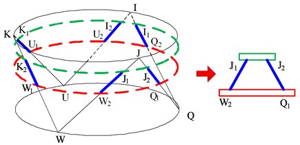
a) Design process of platform
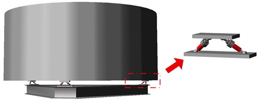
b) Prototype of platform
Fig. 2Simplified dynamic system of supporting leg based on PEA
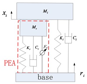
The dynamic function of PEA in an active vibration isolation system is given by Eq. (1).
where, ,,,, and are strain along the axial direction, Young’s modulus, strain caused by input voltage, stress, material damping, density and length. When the base is movable, the force act on the th PEA () can be calculated by Eq. (2):
In which, , and are the cross-section area of PZT, the output displacement, the displacement of base and output displacement generated by input voltage. In this paper, the mass of PEA is much less than that of platform. Then Eq. (2) can be written as Eq. (3).
where denotes the elongation of PEA, and is the time rate of change of length.
The force acts on the payload () is given in Eq. (4):
where:
In which , and are the equivalent damping, stiffness coefficient and generalized control force related to hysteresis displacement generated by input voltage. In the author’s former work, the nonlinear model of hysteresis displacement of and feedforward-feedback control method is researched which will not be discussed here.
2.3. Dynamic modeling of platform
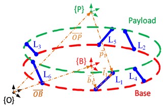
The coordinate system of the proposed platform is shown in Fig. 3. The moving coordinate frame is located at and attached to the up-platform’s center of mass. -axis is set along the centerline of cylinder shell structure. The direction of -axis is along the symmetry of the platform. is a coordinate system attached to the moving base. The center of coincides with the mass center of base. is the global inertial coordinate system. In order to make the kinetic equation in a simple style, the direction of axis of and is set to be the same as . The 6 supporting legs are numbered as illustrated in Fig. 3.
Fig. 3Coordinate system of the platform
Define as the force acted on the payload through supporting legs and as the matrix of actuator forces then:
where is the Jacobi matrix of the platform as given in Eq. (6):
In which is the unit vector of supporting leg vector and is the position vector described in ( 1, 2, …, 6). Substitute Eq. (5-6) into (4), we can get:
where is the matrix of varying speed of lengths, is the set of elongation of PEAs and denotes the general control forces of PEAs. According to Fig. 3 and theorem of vector operation, the following Eq. (8) and Eq. (9) can be obtained:
Let and represent the attitude matrix of the payload and base, respectively, then Eq. (10) is deduced by Eq. (9):
where:
when the motion is in the case of small vibration condition, the elongation vector of actuators can be expressed by Eq. (12):
Substituting Eq. (10) and Eq. (12) into Eq. (7), the force matrix can be written as Eq. (13):
According to Newton-Euler formulation, the kinetic equation of the platform is:
where denotes the mass matrix of payload.
As the center of coincides with the payload mass center and all the directions of axis are along the symmetries axis of cylinder structure, therefore is in the diagonal form and given as. Thus is a diagonal matrix. By assuming the small motion condition, the quadratic item of speed can be neglected. Let to be the generalized control force. Then the actual desired control output is:
In whichis the inverse matrix of . Thus, the kinetic equation is written as Eq. (16) by combining Eq. (13) and (14):
3. Coupled property analysis of platform
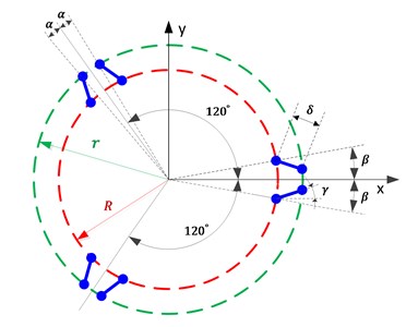
In order to simplify the proof procedure, the parameters angel , and radius and are defined as Fig. 4.
Fig. 4Schematic diagram of parameters
Define matrix and . The th column of and denote and , respectively:
In which is the distance between the mass center of payload and the plane to which the up part of legs are attached.
It’s obvious that equals to the th column of P-B divided by the length of leg (). As all the legs are assumed to be the same, they have the equal ( 1, 2, …, 6). Let the angel between the shadow of the first leg in the - plane and -axis to be and the length of the shadow is . Define matrix , in which the th column denotes :
In which denotes the length of supporting leg and is the projection of in the -axis direction.
3.1. Calculation of matrix
According to Eq. (6), is calculated as Eq. (20):
where is the cross-product anti-symmetry matrix of . The item of can be calculated as shown in Eq. (21):
According to Eq. (19) and the algorithm rules of trigonometric function, one can prove:
Thus is a diagonal matrix. The item of owns the expression shown in Eq. (23):
By using Eq. (17), Eq. (19) and the algorithm rules of trigonometric function, it’s easy to obtain the follow results:
In which is constant that has no affection on the conclusion. Then Eq. (22) is transformed into a simple form given in Eq. (25):
By using the relation listed in Eq. (22) and Eq. (24). The item can be simplified into the description written in Eq. (26):
Substitute Eq. (21), (25) and (26) into Eq. (20), the symmetric structure of is get shown in Eq. (27):
where:
3.2. Calculation of matrix
According to Fig. 3, the following equation is written:
where is a vector starts from the center of base to the center of mass of payload. In the global coordinate frame, , where denotes the distance between the mass center of payload and that of base. Then, Eq. (11) is converted into the following expression:
where:
Thus, Eq. (31) is obtained:
The second term of is calculated as following:
By using the relationship shown in Eq. (22) and Eq. (24), the non-zero items of Eq. (32) can be simplified into Eq. (33) and Eq. (34):
Substitute Eq. (32)-(34) into Eq. (31), one can get:
where:
Eq. (27) and (35) indicate that matrix has the same non-zero elements with. By substituting and into Eq. (16), the parametric expression of kinetic function is obtained.
4. Decoupling control of the platform
As mentioned before, is a diagonal matrix. With the derivation got from chapter 3, it can be concluded that the translation motion along -axis and the rotation around -axis are SISO dynamic systems, while the translation motion in the -axis and the rotation around -axis compose a MIMO dynamic system. The motion along the -axis and the rotation around -axis are in the same situation.
The controllers for two SISO systems can be designed separately. As to the MIMO system, the modal superposition method is adopted to make them in decoupling form [27].
The kinetic equation of the direction is:
where:
As and (or ) are symmetric matrixes, there exists a two-dimensional matrix which satisfies:
In which, and are the generalized eigenvalues of and (or ), and the column ofare the eigenvectors corresponding to and . is a 2×2 unit matrix.
Let, then substitute it into Eq. (37) and multiply both sides of Eq. (37) with . Define as the new generalized control inputs. Thus Eq. (39) is obtained:
Obviously, parameter matrixes are all diagonal. As a result, the system with as input and is decoupled. The processing method of subsystem is discussed in the same way.
With the decoupling algorithm proposed, the dynamic system is translated into six independent SISO systems. The vibration controller for each system is designed separately with LQR method to suppress the vibration response [28]. Let’s take the -axis SISO system as example. Define as the state variables and given as, as the desired control input that is equal to . The state equation of vibration along z direction can be written as Eq. (40):
where is the perturbation vector. is the output which is chosen as . The matrixes in Eq. (40) are listed below:
The objective of control system is to minimize acceleration response of isolated object. The LQR coefficients are obtained by minimizing the cost function given in Eq. (41):
where is the weighting matrix of state variable which is symmetric positive semi-definite, is the symmetric positive definite weighting matrix of input signal.
The control signal is in the form of Eq. (42):
where is a vector obtained by solving the Riccati equations given as Eq. (43) and Eq. (44):
During the parameters adjusting procedure of the LQR controller, and are regulated separately according to the control performance. For the dynamic system established in this paper, is a diagonal matrix and. Usually, the regulation method of is , where is the initial real matrix and is the gain coefficient. is a real diagonal matrix. In this paper, is set as one.
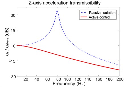
If the base vibrates in the direction, the acceleration transmissibility of payload along -axis is illustrated in Fig. 5, where the dashed line is the result for passive isolation and the solid line is the transmissibility when the active controller is applied. It can be observed that the active control method proposed significantly improves the dynamic characteristic of the platform. The vibration at the resonant frequency is attenuated by more than 30 dB. During the low-frequency band below 82 Hz, the controller effectively reduces the energy transfer from base to the payload, which is impossible for the traditional passive isolation. While in the high-frequency range, the vibration isolation effects of the two methods get close to each other. It’s worth noting that the vibration isolation effect is still improved by nearly 5 dB before 200 Hz.
Fig. 5Acceleration transmissibility of the platform in z-axis
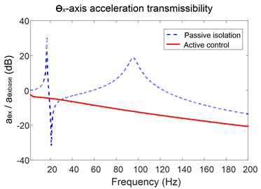
When the excitement on the base is in the -axis direction, as analyzed above, there is only -axis direction vibration response and rotational response around -axis. Fig. 6(a) is the -axis acceleration transmissibility of the payload. The dashed line is the passive isolation result which indicates that the platform owns two resonant frequencies at 18 Hz and 95 Hz, and an anti-resonant frequency at 38 Hz. The acceleration response presents the attenuation characteristics except the frequency bands near resonant frequencies.
With the active controller working, the -axis acceleration transmissibility is shown as solid line. It can be found that the control method makes the vibration isolation performance of the platform worse at the frequency nearby anti-resonant peak. But during the other frequency range, the controller can achieve a significant performance increase. Fig. 6(b) is the coupling vibration response around y-axis. By comparing the result, the controller proposed decreases acceleration transmissibility by average of more than 5dB when the excitation frequency is above 10 Hz.
Fig. 6Acceleration transmissibility of the platform in x-axis and around y-axis
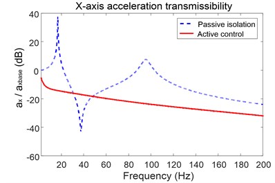
a) Transmissibility of the platform in -axis
b) Transmissibility of the platform around -axis
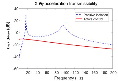
Fig. 7(a) indicates the angular acceleration transmissibility of the payload when the base is forced by time-varying torque around -axis. As it is an isolated SISO system, the transmission property is similar to that of -axis direction vibration. The natural frequency is 29 Hz and nearly 40 dB attenuation is achieved with the control algorithm. The transmissibility curves gradually approach to each other when the frequency is above 160 Hz.
Fig. 7Acceleration transmissibility of the platform around z-axis and x-axis
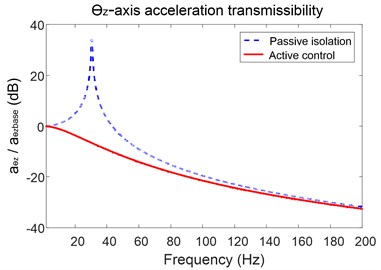
a) Transmissibility of the platform around -axis
b) Transmissibility of the platform around -axis
Fig. 7(b) indicates the vibration isolation performance when the base is in pitching motion state. Similar to transverse vibration properties, the controller is effective except the anti-resonant frequency band.
The simulation results presented in Fig. 5-7 prove the platform and vibration control method are effective during the frequency range of 20 Hz-200 Hz.
5. Experimental verification
The -axis direction vibration isolation experiments are implemented to validate the effectiveness of the proposed platform and the decoupling control algorithm. The experimental setup is shown in Fig. 8. The mechanical parts mainly include cylindrical payload, base, suspension system and leveling device. The suspension system is used to eliminate static loads act on PEAs in the initial state. The leveling device is adopted to guarantee the -axis of platform vertical to the horizontal plane. The control part is consisted of six PEAs, piezoelectric drive power, sensors, oscilloscope, signal generator and Matlab/Simulink real-time (XPC). XPC is an easy and efficient way to realize rapid control, which is composed of target PC and host PC. The control program is debugged and tested on the host PC and then compiled into C code which is executable in target PC. The target PC carries data acquisition cards which collect the signal of sensors and outputs control voltage.
The experiments with sinusoidal excitation at certain frequencies are conducted as shown in Fig. 9. As the target frequency band is 5 Hz to 200 Hz, the frequencies are set to be 5 Hz, 50 Hz, 80 Hz and 150 Hz. The performance of isolation system is not obvious when the excitation frequency is 5 Hz. The response of payload is nearly the same to the motion of base. When the frequency rises to 50 Hz, the active control system can significantly reduce the acceleration response of payload to about 40 % relative to the excitation signal, while the passive isolation has no effect. Fig. 9(c) depicts that the perturbation from base is eliminated by about 20 % when the controller is working, while it’s significantly magnified nearly five times when the power of control system is off. Fig. 9(d) indicates the response of the platform under excitation at 150 Hz from the base. Both of the vibration isolation methods are effective, and the perturbation is attenuated by nearly 80 %.
Fig. 8Photograph of experimental setup
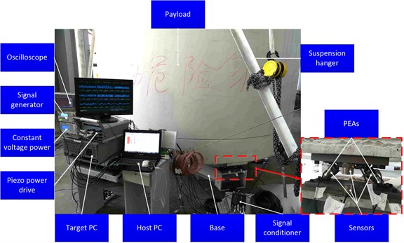
Fig. 9Experimental results under different frequency sinusoidal excitation
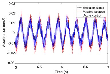
a) 5 Hz
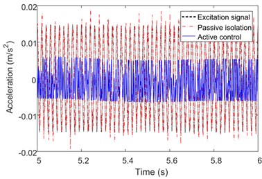
b) 50 Hz
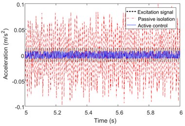
c) 80 Hz
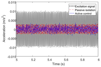
d) 150 Hz
Fig. 10 presents the acceleration transmissibility of the platform when the excitations act on base in the -axis direction. The dash-dotted line is the vibration isolation performance of the platform without the controller. The solid line indicates the acceleration transmissibility with control. By comparing the experimental result, the platform designed in this paper effectively decreases the vibration response of the payload in the frequency range above 100 Hz. For the frequency band during 20 Hz-100 Hz, the active control system obviously improves the average vibration isolation performance of the platform by more than 5 dB. At the main resonant peak, the acceleration response is reduced by about 20 dB.
Fig. 10Experimental result of Acceleration transmissibility
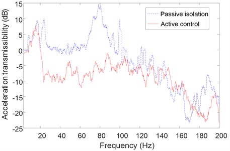
It can be found that resonant frequencies nearby 20 Hz are different from the simulation result shown in Fig. 5. The main reason is the payload is assumed as rigid which is actually a flexible structure with multi-modes in the frequency range tested. Parts of the modal frequencies of the payload are excited and these lead to the rise of acceleration response. What’s more, the performance in the high frequency band is not as good as the simulation results. To further improve the vibration isolation performance of the platform, much more works will be conducted to reduce the effects of the error sources for a 6DOF mechanism and to enhance the robust characteristic and adaptive ability of the proposed decoupling control method. In general, the effectiveness of the six-axis orthogonal vibration isolation platform with piezoelectric actuators can be validated.
6. Conclusions
1) In this paper, a six-axis orthogonal vibration isolation platform with piezoelectric actuators is designed. The proposed platform satisfies the demands of heavy load, small installation space and multi degree of freedom vibration isolation. The dynamic model of platform is established and analyzed, which indicate the coupling characteristic of the platform with the layout of six PEAs around the axis of the symmetry of cylindrical payload.
2) The kinetic equation of the platform is decoupled into six SISO systems by combining the modal superposition method. The control strategy based on LQR control method for each SISO subsystem is proposed. The simulation and experimental results indicate the proposed six-axis orthogonal active vibration isolation platform with piezoelectric actuators can effectively reduce the dynamic response of payload in the frequency range of 20 Hz-200 Hz by average of 5 dB.
References
-
Ortiz G., Farr W. H., Sannibale V. A Sub-Hertz, Low-Frequency Vibration Isolation Platform. 2011.
-
Spanos J., Rahman Z., Chu C., O’Brien J. Control structure interaction in long baseline space interferometers. Automatic Control in Aerospace, Vol. 25, Issue 22, 1992, p. 463-470.
-
Boroson D. M., Biswas A., Edwards B. L. MLCD: Overview of NASA’s Mars laser communications demonstration system. Proceedings of SPIE, The International Society for Optical Engineering, Vol. 5338, 2004, p. 16-28.
-
Ford V., Levine-West M., Kissil A., Kwack E., Ho T., Dumont P., et al. Terrestrial planet finder coronagraph observatory summary. Proceedings of the International Astronomical Union, Vol. 1, Issue 200, 2005, p. 335-344.
-
Pedreiro N., Trankle T. L., Tenerelli D. J. Control system for terrestrial planet finder interferometer. Proceedings of SPIE, 2003, p. 581-592.
-
Gutierrez H. L. Performance Assessment and Enhancement of Precision Controlled Structures during Conceptual Design. Massachusetts Institute of Technology, 1999.
-
Cobb R. G., Sullivan J. M., Das A., Davis L. P., Hyde T. T., Davis T., et al. Vibration isolation and suppression system for precision payloads in space. Smart Materials and Structures, Vol. 8, Issue 6, 1999, p. 798.
-
Davis P., Cunningham D., Harrell J. Advanced 1.5 Hz passive viscous isolation system. Structures, Structural Dynamics, and Materials Conference, Vol. 32, 2013, p. 43.
-
Anderson E. H., Fumo J. P., Erwin R. S. Satellite ultraquiet isolation technology experiment (SUITE). Aerospace Conference Proceedings IEEE, Vol. 4, 1999, p. 299-313.
-
Mosier G. E., Howard J. M., Johnston J. D., Parrish K. A., Hyde T. T., Mcginnis M. A., et al. The role of integrated modeling in the design and verification of the James Webb Space Telescope. Proceedings of SPIE, Vol. 5528, Issue 1, 2004, p. 341-355.
-
Bronowicki A. J. Vibration isolator for large space telescopes. Journal of Spacecraft and Rockets, Vol. 43, Issue 1, 2006, p. 45-53.
-
Stewart D. A platform with six degrees of freedom. Proceedings of the Institution of Mechanical Engineers, Vol. 180, Issue 1, 1965, p. 371-386.
-
Foshage G. K., Davis T., Sullivan J. M., Hoffman T., Das A. Hybrid active/passive actuator for spacecraft vibration isolation and suppression. Proceedings of SPIE, Vol. 2865, 1996, p. 104-122.
-
McMickell M. B., Kreider T., Hansen E., Davis T., Gonzalez M. Optical payload isolation using the miniature vibration isolation system (MVIS-II). Proceedings of SPIE, V131, p. 2007-1672.
-
Rivin E. I. Dynamic properties of vibration isolation systems. American Journal of Physiology, Vol. 147, Issue 4, 1946, p. 603-615.
-
Karnopp D. Active and semi-active vibration isolation. Journal of Vibration and Acoustics, Vol. 17, Issue 1, 1995, p. 177-185.
-
Preumont A. Active vibration isolation. Vibration Control of Active Structures, Vol. 125, Issue 3, 2002, p. 539-553.
-
Abu Hanieh A. Active Isolation and Damping of Vibrations Via Stewart Platform. Universite Libre De Bruxelles, 2003.
-
Spanos J., Rahman Z., Blackwood G. A soft 6-axis active vibration isolator. Proceedings of the American Control Conference, Vol. 1, 2002, p. 412-416.
-
Thayer D., Campbell M., Vagners J., von Flotow A. Six-axis vibration isolation system using soft actuators and multiple sensors. Journal of Spacecraft and Rockets, Vol. 39, Issue 2, 2002, p. 206-212.
-
Abu Hanieh A. Piezoelectric Stewart platform for general purpose active damping interface and precision control. Proceedings of the 9th European Space Mechanisms and Tribology Symposium, 2001, p. 331-334.
-
Petitjean B., Leblhan D. Robust control of a satellite truss structure. 10th International Conference on Adaptive Structures and Technologies, Paris, France, 2000, p. 313-319.
-
Li Y., Xu Q. A totally decoupled piezo-driven XYZ flexure parallel micropositioning stage for micro/nanomanipulation. IEEE Transactions on Automation Science and Engineering, Vol. 8, Issue 2, 2011, p. 265-279.
-
Chen Y., Mcinroy J. E. Decoupled control of flexure-jointed hexapods using estimated joint-space mass-inertia matrix. IEEE Transactions on Control Systems Technology, Vol. 12, Issue 3, 2004, p. 413-421.
-
Yang C., Huang Q., Han J. Decoupling control for spatial six-degree-of-freedom electro-hydraulic parallel robot. Robotics and Computer-Integrated Manufacturing, Vol. 28, Issue 1, 2012, p. 14-23.
-
Chen Y., Mcinroy J. E. Identification and decoupling control of flexure jointed hexapods. IEEE International Conference on Robotics and Automation, Vol. 2, 2000, p. 1936-1941.
-
Newland D. E. Mechanical Vibration Analysis and Computation: Courier Corporation. 2013.
-
Argentim L. M., Rezende W. C., Santos P. E., Aguiar R. A. PID, LQR and LQR-PID on a quadcopter platform. International Conference on Informatics, Electronics and Vision, 2013, p. 1-6.
Cited by
About this article

This research is funded by the National Natural Science Foundation of China (Grant No. 61304037) and National Basic Research Program of China (Grant No. 613235).
