Abstract
Some components in Double horse head (DHH) pumping unit may occur cracking failure due to high cycle alternating stress, and this makes the research on dynamic stress simulation for them more interesting topic in its maintenance operation. This paper aims to improve the accuracy of dynamic stress simulation model through a parameter optimization method for the cable joints in DHH pumping unit. A series of cylinders was employed to model the steel cable, and the back horse head was also transformed to flexible body, then a rigid-flexible multibody dynamics model with cable was constructed to simulate the dynamic stress of components in DHH pumping unit. Stiffness and damping coefficient in cable joints have a significant effect on the model performance, and an unreasonable value may cause a strong vibrational and undesirable model response, therefore, a Memetic Algorithms based method was proposed to optimize them for improving the simulation accuracy using tested stress as objective function. Results show that the dynamic stress simulated from improved model is much closer to the experimental test compared with the original model, and these optimized parameters are also valid for the model in other working condition.
1. Introduction
Artificial lift beam pumping unit is widely employed to extract oil on most wells all over the world, and more than 70 % of the beam pumping units is the conventional type [1, 2]. However, due to the unbalance of crank torque, the system efficiency is still very low, and the high load alternating amplitude often damage the key components. The DHH pumping unit, which was designed by a variable parameters four-bar mechanism, is an improved beam pumping unit, and it can settle the dead angel problem in conventional type and has the characteristics of long stroke. Therefore, the DHH pumping unit demonstrates characteristics of an excellent counterbalance efficiency and better energy conservation ability [3, 4]. However, there still exists some remain unbalanced crank torque, and it may cause high cycle alternating stress which lead to cracking failure of some key components such as cracks in area connecting walking beam and back horse head. This makes the stress simulation and analysis for key components of beam pumping units more interesting topic in its maintenance operation. Larrainzar [5] has presented an analysis of the fatigue crack growth and the corresponding residual life evaluation of the walking beam in an oilfield pumping unit.
Nowadays, multi-body dynamics simulation and finite element analysis software, such as ADAMS and ANSYS, are well developed and widespread, and this makes the researchers easier to analyze the dynamic stress of complex machinery by a rigid - flexible coupling dynamics model. Several researchers have used ADAMS software to solve the multibody dynamics equations for mechanical system. Yu [6] has conducted a co-simulation between ADAMS and ANSYS to calculate stress of the crankshaft in reciprocating compressor, and then investigated the fatigue analysis and remain life prediction by using the simulated stress. Imed Khemili [7] has investigated the dynamic performance of a slider-crank mechanism with a rigid-flexible dynamic model under ADAMS. Therefore, rigid-flexible dynamics model is valid method for the dynamic stress analysis of components in DHH pumping unit.
Cables are widely used in mechanical equipment to transmit motion and force between components. Despite ADAMS has comprehensive capabilities for mechanical systems modeling, it is still short of straightforward methods to model some very basic standard mechanical device components. One of these components is the cable which can contact with a general surface [8, 9], such as the steel cables in DHH pumping unit. ADAMS usually employs cylinders with bushing and contact joints to model it. However, there are a plurality of parameters in bushing and contact joints need to set manually, and they play a great effect on flexibility of cable and the contact force, and hence on the dynamic performance of the multibody model. Though there are recommended values for these parameters, a difference still exists from real one, and usually it may cause the model runs unstable. The unreasonable cable flexibility and contact force will lead to an impulsive vibrational response of the model which is meaningless compared with the real experimental test.
This make the researchers difficult to simulate the dynamics behavior accurately for model with cable. Hence, it may be an effective approach to take the improvement of simulation accuracy as an optimization issue which treat the parameters of cable joints as variables and the dynamic response of experimental tests as optimization objective function. Several research works have been conducted with the optimization of parameters for mechanical systems with joints, Erkaya and Uzmay [10, 11] have employed genetic algorithm approach to optimize the link parameters for minimizing the error between desired and actual paths due to clearance. Zhao [12] has optimize the parameters of joint model with clearance for a two stage reciprocating compressor.
Taking the stress simulation of key components in DHH pumping unit as a special example, this paper presents an approach to optimize parameters of the joint for cable in order to increase the accuracy of multibody dynamic model. Section 2 introduce the pumping unit structure. In Section 3 the bushing joint and contact force model was described. Section 4 gives the multibody dynamic model and the problem. In Section 5 the parameter optimization method was presented and applied. Finally, we draw the conclusions in Section 6.
2. The DHH pumping unit
As an improved beam pumping unit from conventional type, the DHH pumping unit (illustrated in Fig. 1), which was designed by a variable parameters four-bar mechanism, has another back horse head connected to the walking beam with two pins. It also uses the flexible steel cables driving the back horse head instead of the rigid connecting rod, which settles the dead angel problem in conventional type and has the characteristics of long stroke.
Fig. 1The structure of DHH pumping unit
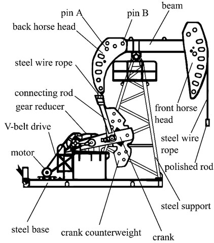
The effective length of back arm in walking beam will change with the rotate angel of crank. When the suspension point load is large, the effective length of the beam back arm will become long, which makes the crank torque is not too heavy. While when the suspension point load is small, the effective length of the beam back arm will become smaller, so that the crank torque is not too light. This reduce the amplitude of crank torque for a better balance effect, and hence lower energy consumption and the quality of the machine.
Though the DHH pumping unit demonstrates characteristics of an excellent counterbalance efficiency and better energy conservation ability, there still exists some remain unbalanced crank torque, and it may cause high cycle alternating stress which lead to cracking failure of some key components, especially fatigue cracks near the hole in back horse head. This makes the stress simulation and analysis more interesting topic in its maintenance operation.
3. Review of bushing joint and contact force model
3.1. The force model of bushing joint
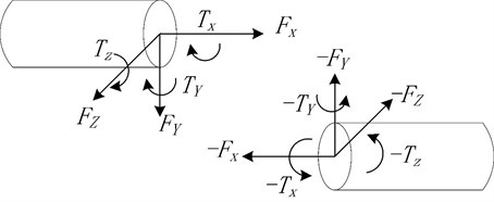
As shown in Fig. 2, bushing joint presents the spring and damper forces acting between two parts. It defines the force and torque magnitudes using six Cartesian components (, , , , , and ), which are a linear function of the translational and rotational displacement between two coordinate systems moving with the two parts [8, 9].
The following constitutive equations define how a force and a torque were applied to the parts according to the displacement and velocity between marker and in a bushing joint:
The bushing element applies an equilibrating force and torque to the marker in the following way:
According to the calculation method of materials mechanics, the coefficients to calculate bushing joint force are defined as follows:
Fig. 2The spring and damper forces acting between two parts in bushing joint
3.2. Elastic-damping contact force model
To calculate the contact forces for the steel cables and horse head in the multibody dynamic model efficiently, the numerical description of contact force model needs to pay special attention. For the modeling of the contact under ADAMS, we have used IMPACT-Function. In this method, ADAMS/Solver can give a continuous flow responses of accelerations, velocities, positions and forces for all contact elements.
The normal contact force has two components: rigidity and viscous damping. The component of rigidity is a function of the penetration , while the viscous damping is a function of the speed of penetration.
In this model, the normal force of contact is given by the following relation [13]:
The instantaneous damping coefficient is defined as:
4. The multibody dynamic model of DHH pumping unit
4.1. The 3D model of pumping unit
To simulate the dynamic stress of DHH pumping unit, a multibody dynamic model was built with software ADAMS. A CYJS10-5-37HB type DHH pumping unit is used as the research case, and the working and structural parameters of this pumping unit were listed in Table 1. The 3D geometric outline of pumping unit was first constructed by Solidworks, and then was imported into ADAMS. To maintain the kinematics and dynamics constraint, a series of joints were added to the model. The three-phase asynchronous motor, gearbox and support were connected to the base in real working condition; therefore, they were fixed to ground. The walking beam can revolute around steel support bearing, so they were assembled to support pin with revolute joint. Cranks was linked to the connecting rod and the shaft of gearbox with revolute joints respectively. The two horse head were connected to the walking beam with fixed joints.
Table 1The key parameters of pumping unit CYJS10-5-37HB
The maximum load of suspension point (KN) | 100 | |
Stroke (m) | 4 | |
Frequency of stroke (min-1) | 5 | |
Balanced manner | Crank balanced | |
Reducer | Ratio | 28 |
Center distance (mm) | 850 | |
Torque (KN∙m) | 37 | |
Motor | Type | Y225S-8 |
Power (KW) | 18.5 | |
Rotating speed (r/min) | 730 | |
Drive belts | 6×ZV15J-6730 | |
Minimum height of suspension point (mm) | 1600 | |
Length- width -height (m) | 9.3×2.0×10.5 | |
Total weight (Kg) | 2400 | |
The area near two pin holes in back horse head often occurs fatigue cracks, and this paper aims to simulate the dynamic stress distribution of back horse head. Therefore, the back horse head connected to the walking beam was created as a flexible body. This unit was firstly meshed in ANSYS software by using the Solid45 element, and then was created with two external points in the center of each pin hole, finally was imported into ADAMS software through a modal neutral file (MNF). The flexible back horse head is shown in Fig. 3, and its details of meshing characteristics are listed in Table 2. The back horse head was connected to the walking beam by two fixed joints between the external points and pins in walking beam.
Fig. 3The flexible model of back horse head
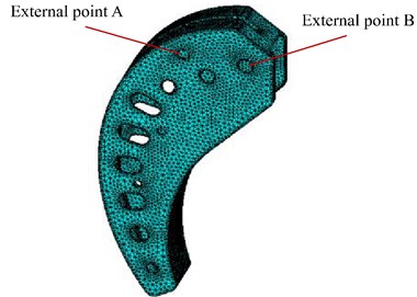
Table 2Meshing characteristics of the back horse head
Element type | Element number | Eigenmodes number |
Solid45 | 13245 | 6 |
4.2. The model of steel wire ropes
In this pumping unit, the crossbeam drives the back horse head by steel cables, and the front horse head also drives the polish rod with steel cables. However, ADAMS software have no parts to model cable, usually the cable was modeled by cylinders linked with bushing joints. According to the structural parameters of given type pumping unit, a cylinder 10 mm diameter and 50 mm long was created and connected to the crossbeam with revolute joint, and then a series of cylinders in the same size were built by ADAMS macro along the route of real steel cables until it reached the fixed point in the back horse head. To simulate the flexibility of steel cables, bushing joints were also applied between each two cylinders by ADAMS macro. In the bushing joint, the stiffness and damping coefficient in different directions used the recommended values.
In the real working condition, the steel cables drives the back horse head and walking beam rotating around the steel support. The contact points between steel cables and back horse head are changing with the angle of walking beam. Therefore, a series of contact forces between back horse head and cylinders in steel cables should be added besides the fixed joint. This model employs the IMPACT function available in the ADAMS function library to simulate the contact force. The stiffness and damping coefficient in the IMPACT function also used the recommended values.
The steel cables between the front horse head and the suspension point was modeled by the same method. Fig. 4 demonstrated the rigid-flexible model of DHH pumping unit built in ADAMS.
4.3. The load and simulation
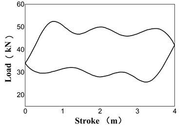
Suspension point load and gearbox shaft motion are the two loads of this model. A 5 rpm gearbox shaft rotate motion was applied to the end of gearbox shaft near cranks, and an experimental tested and smoothed suspension point load (as shown in Fig. 5) was applied to the suspension point in this model.
The selection of solver and its integrator are key factors that affect the solution efficiency and accuracy. This simulation used Gear Stiff integrator (GSTIFF) and (SI1) integrator formulation. The integration tolerance was set as 0.00001 and the step size was 0.00001 second.
Fig. 4The DHH pumping unit dynamic model
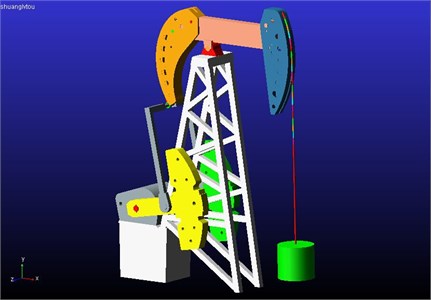
Fig. 5The experimental suspension point load of pumping unit
4.4. Experimental test
To verify the simulated results, an experimental test was conducted for the CYJS10-5-37HB type DHH pumping unit to obtain the suspension point indicator diagram and dynamic stress process in the same working condition. In this test, a wireless indicator diagram collector, as shown in Fig. 6 left part, was employed to collect the load and displacement signal of suspension point, and then the tested signals were transformed to the indicator diagram illustrated in Fig. 5.
Fig. 6The test of indicator diagram and stress for a CYJS10-5-37HB type DHH pumping unit
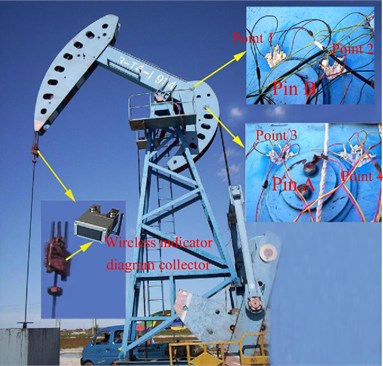
To test the stress changing process of area near pin A and pin B, four vertical arranged strain gauges with full bridge circuit, as point 1-4 demonstrated in Fig. 6 right part, were bonded to the surface. The strain signal was recorded with the indicator diagram synchronously, and then was transformed to stress accompanied with crank rotation angle in computer.
4.5. Results and discussion
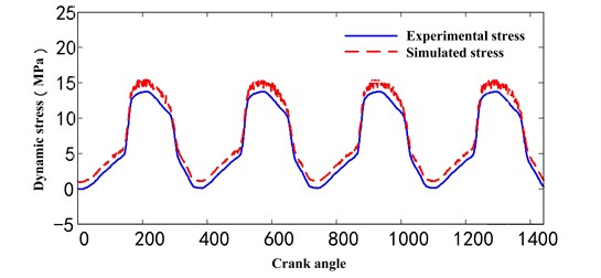
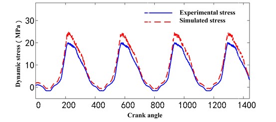
We choose one test point from each pin, and the model experimental tested dynamic stress of point 1 and point 3 were shown as blue line in Fig. 7(a) and Fig. 7(b) respectively. We can observe that dynamic stress in two points both exhibit periodic fluctuations, and the alternating stress amplitude is 12.87 MPa for point 1, and 21.87 MPa for point 3. Though they are both in the range of material allowable stress, point 3 appears tensile and compressive stress alternately, and this made the components easier to occur fatigue cracks after a long and high frequent cycle working period.
Fig. 7The comparison between simulated and experimental tested stress
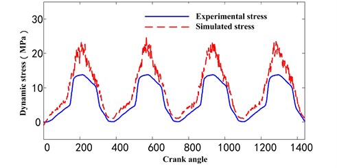
a) Point 1
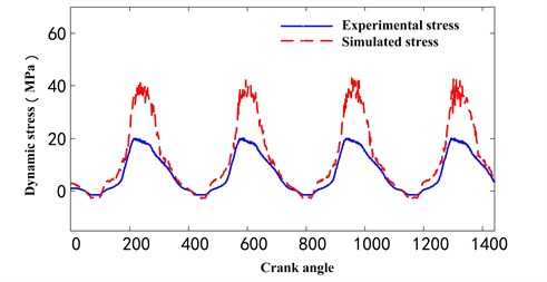
b) Point 3
The model simulated dynamic stress of point 1 and point 3 were also shown as red line in Fig. 7(a) and Fig. 7(b) respectively. We can observe that significant differences exist between simulated and experimental stress in amplitude, and there are also many vibrational peaks in the simulated stress due to the unreasonable cable flexibility and contact force, while the tested stress are smooth relatively. After serval trials, we found the differences in amplitude are mainly caused by unsuitable flexibility of simulated steel cables, and the vibrational peaks is probably due to the unstable contact force. While the stiffness and damping coefficient are key factors for performance in flexibility and contact force of cables, therefore, by adjusting the parameters of the stiffness and damping coefficient is an alternative way to improve the model.
5. The improvement of model with parameter optimization
As discussed above, the stiffness and damping coefficient are the key factors in the performance of bushing joint and contact model. Though there are recommended values for parameters according to material properties and geometric dimensions, they may not be the best one for all applications. We can improve the model accuracy by changing the key parameters. So, we treat this subject as an optimization problem to find the most similar simulated stress compare to the experimental one, in which the key parameters of model are changed to variables.
Evolutionary Algorithms (EAs) are a class of search and optimization techniques that work on a principle inspired by nature: Darwinian evolution. While the pure EAs are not well suited to fine tuning search in complex combinatorial spaces and that hybridization with other techniques can greatly improve the efficiency of search [14]. In 1989, Moscato [15] firstly proposed Memetic Algorithms (MAs), which used the local heuristic search to imitate the mutation process backed up by large amount of professional knowledge. MAs are extensions of EAs that apply separate processes to refine individuals efficiently and effectively, and it has been applied in a number of different areas, so far, MAs have been widely used for solving many optimization problems, such as scheduling problems [16], combinatorial optimization problems [17], multi-objective problems [18] and other applications. Therefore, this paper employs MAs to fulfill the optimization process of parameters in pumping unit model. Here we employ the typical Genetic Algorithms (GA) as the global search method and Hill Climbing as local search strategy [19].
The parameter optimization process was implemented with the co-simulation between software ADAMS and MATLAB. The stress simulation was conducted using the multibody dynamics model presented in section 4 by ADAMS while the optimization process based on Memetic Algorithms were executed by MATLAB.
In MATLAB, Memetic Algorithms were programed to create individuals with different chromosomes, start the stress simulation in ADAMS, calculate the fitness function, judge the termination condition, conduct the crossover and mutation operation, and give the optimal results.
While the stress simulation process in ADAMS was used as a sub function in MATLAB. ADAMS macro can execute a series of commands without GUI operation. In this subject, the commands such as parameters setting and simulated solutions output were written as a macro, and ADAMS can run the macro automatically with a parameter input and a simulated stress output. In MATLAB, ADAMS macro file will be written for each individual, and executed as a sub function in the process of Memetic Algorithms.
5.1. The chromosomes and fitness function of GA-based MAs
In this model, the stiffness and damping coefficient of bushing joint and contact model were treated as variables, and there are six stiffness coefficients and six damping coefficients in bushing joint of steel cables and one stiffness coefficients and one damping coefficients in contact model between the steel cables and horse head. While the , in Eq. (4), here we use one variable to stand for the equal and to reduce the number of variables, and stands for the equal and . The damping coefficients are defined in the same rule. Therefore, the chromosome is defined as the permutation of these parameters:
The objective of this optimization is to find the most similar simulated stress of area near pin A and pin B compare to the experiential one, that is, minimize the error between simulated and experiential stress in the same test point. This paper utilizes the mean square error (MSE) between simulated and experiential stress in each test point to evaluate their similarity, and we give the MSE of each test point an equal weight, therefore, the objective function is defined as:
Minimize .
Subject to , .
Subscript and are the upper and lower value of the variable range.
5.2. Algorithm and flowchart of optimization method
This parameters optimization operation was implemented through the co-simulation between ADAMS and MATLAB. The calculations of MAs were conducted in MATLAB while the dynamics simulation of pumping unit was executed in ADAMS.
The parameters optimization process was implemented according to the following steps:
Step 1: The population, that is the parameters permutation including the stiffness and damping coefficient of bushing joint and contact model, were initialized randomly;
Step 2: The macro file of DHH pumping unit dynamics model was created by using the parameters in each individual of population, each individual corresponds to one macro file;
Step 3: ADAMS run all the macro files automatically, each individual obtained a pair of simulated dynamic stress near pin A and pin B in back horse head;
Step 4: MATLAB imported the simulated and experimental stress, and calculated the MSE as fitness function for each individual;
Step 5: If one of the fitness was equal to the given threshold value, or the generation reach the max number set previously, the calculation was finished, and the best results was obtained.
Step 6: If the operation continues, a new generation of offspring were selected by using the Roulette Wheel rule from parents;
Step 7: The new offspring conduct a greedy crossover based hill climbing to search some elite offspring. The elite individual is taken as one parent and another parent is selected from the current population using a roulette wheel. Then, a special uniform crossover is executed between these two parent individuals to generate an offspring. The offspring will replace the elite individual in the current population if it has a better fitness than the elite [14];
Step 8: Subsequently, the offspring were further refined by a steepest mutation-based hill climbing method. The chromosome only changes several bits randomly when executing one mutation operation on it. The elite individual is picked out from the current population and several random bits are changed. If the newly mutated individual has a better fitness, it will replace the elite individual [19];
Step 9: When the new generation of population was formed, this algorithm returned to step 2 to find a better fitness.
Based on the steps discussed above, the flowchart of model parameters optimized method was shown in Fig. 8.
5.3. Simulation
In the optimization process of model parameters, the steel cables of front and back horse head use the same stiffness coefficient and the coefficient . The recommended values and were defined as the center of value for variables and , and the variables and of each individual were created in the value interval from 10-4 to 104 multiples of value center and respectively.
In the optimization process of MA, the MA parameters plays an important role on the optimization results. Furthermore, due to the plentiful variables in this model, the variables may easily fall to local optimum values. Therefore, for searching a better global optimum values, orthogonal test method was employed to find the best MA parameters for this model. The best MA parameters are as follows: the size of population is 80, the maximum iterations are 60, the crossover probability is 0.9, and the mutation probability is 0.05.
5.4. Results and discussion
The optimized parameters, that is, stiffness coefficient and coefficient , MSE and relative errors were listed in Table 3. To verify this method, the simulation results using recommended parameter values were also shown in Table 3. We can see that obvious differences of parameters exist between two models, and the MSE and relative errors of the improved model is much lower compared with that of recommended parameters model.
Table 3Comparison between solutions for different methods
Parameters | Optimized parameter model | Recommended parameter model | |
Bushing joint | 7.81×10⁸ | 3.14×10⁸ | |
2.26×10⁸ | 1.25×10⁸ | ||
2.26×10⁸ | 1.25×10⁸ | ||
204 | 110 | ||
308 | 137 | ||
308 | 137 | ||
5201 | 400 | ||
4287 | 400 | ||
4287 | 400 | ||
45 | 40 | ||
56 | 40 | ||
56 | 40 | ||
Contact model | 4.01×10⁸ | 1.00×10⁶ | |
1.02×10³ | 50.0 | ||
MSE | Point 1 | 1.11×10³ | 1.23×10⁴ |
Point 3 | 1.34×10³ | 1.56×10⁴ | |
Relative error | Point 1 | 25.41 % | 178.24 % |
Point 3 | 32.12 % | 234.22 % | |
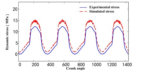
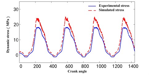
The simulated stresses of the improved model for point 1 and point 3 were illustrated in Fig. 9, and we can observe that, compared with the results simulated by the recommend parameters values under the same working condition in Fig. 7, the amplitude and distribution of simulated stress in Fig. 9 were closer to experimental stress in amplitude, and the peaks were suppressed significantly in the simulated stress. While there are still some differences because of several reasons: (1) The bushing joint and contact force model still exist theoretical shortage need to improve compared with real working condition; (2) The cylinders connected with bushing joints are a series of discrete rigid bodies, their dynamic performance are close to, but different from real continuous flexible steel cables; (3) Some structural details were simplified in the model, so the mass centers of components are some different. Despite the differences in the simulation results, it is a novel way to improve the dynamics response simulation accuracy for mechanism with steel cables.
Table 4Comparison between solutions for another working condition
Parameters | Optimized parameter model | Recommended parameter model | |
MSE | Point 1 | 1.45×10³ | 1.78×10⁴ |
Point 3 | 1.67×10³ | 2.08×10⁴ | |
Relative error | Point 1 | 32.14 % | 218.25 % |
Point 3 | 35.15 % | 256.32 % | |
For the purpose of verifying the applicability of optimized parameters in another way, we use the optimized parameters to simulate dynamic stress with the same pumping unit model in a different working condition, which the crank rotating speed is 4 rpm and an experimental tested suspension point load was applied to the suspension point. The simulated dynamic stress by the optimization parameters model was shown in Fig. 10 together with the experimental tested one, and the detailed comparison was given in Table 4. We can observe the amplitude and distribution of simulated dynamic stress is similar to that of the experimental tested dynamic stress, and though bigger than the MSE and relative error in Table 3, they are still in an acceptable range. So, it is feasible to simulate the dynamic stress of model for different working conditions by using the parameters optimized from one working condition, which can achieve an economic efficiency by the reduction of experimental tests. The model built in this paper can not only be used to simulate the dynamic stress of components for a safety assessment but also be employed to balance the crank torque for an energy saving.
Fig. 8Flowchart of model parameters optimized method
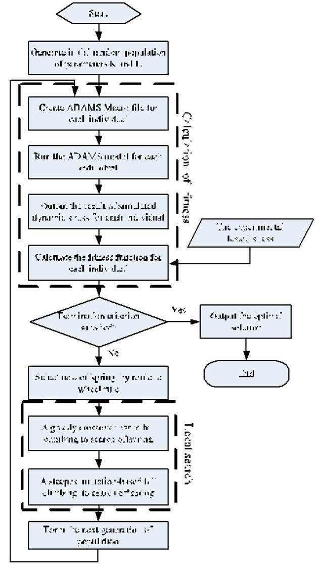
Fig. 9The comparison between experimental stress and simulated stress with optimized parameters
a) Point 1
b) Point 3
Fig. 10The comparison between experimental stress and simulated stress with optimized parameters in another working condition
a) Point 1
b) Point 3
6. Conclusions
To improve the simulation accuracy for multibody dynamics model of mechanism with cable, a parameters optimization method was presented in this paper.
A multi-body dynamics model of DHH pumping unit was built in ADAMS by using cylinders with bushing joint to model the steel cables, and the simulated dynamic stress has significant difference from the experimental tested one;
The stiffness coefficient and the damping coefficient of joints were found as key factors of model performance, and a Memetic Algorithms based method and its detailed flowchart was proposed to optimize them for the improvement of model accuracy;
The dynamic stress simulated using this parameters optimization method is closer to that of experimental test, and these optimized parameters are also valid for the model in other working condition.
The paper proposes an alternative idea for the improvement of multibody dynamics model with cable, and the model built in this paper gives an effective way to further analyze the dynamic stress performance of pumping unit.
References
-
Yijie L., Tongjian W., Xinw, Weiquan L. Simulation research on hydraulic hybrid assistant beam pumping unit. Proceedings of the Institution of Mechanical Engineers, Part C: Journal of Mechanical Engineering Science, Vol. 230, Issue 11, 2016, p. 1795-1804.
-
Hongqiang L., Jun L., Jiuqiang H., An J. An energy saving system for a beam pumping unit. Sensors, Vol. 16, Issue 5, 2016, p. 685-697.
-
Yang D. P., Gao X. S., Dai Y. Dynamic simulation system of variable parameter flexible linkage mechanism of dual horse head pump unit. Chinese Journal of Mechanical Engineering, Vol. 46, Issue 9, 2010, p. 59-66.
-
Fu H. L., Zou L. Q., Wang Y. Study on design and simulation analysis of the double horse-head pumping unit based on the compound balance structure. Proceedings of the Institution of Mechanical Engineers, Part C: Journal of Mechanical Engineering Science, Vol. 229, Issue 16, 2015, p. 3034-3046.
-
Larrainzar C., Korin I., Perez Ipiña J. Analysis of fatigue crack growth and estimation of residual life of the walking beam of an oilfield pumping unit. Engineering Failure Analysis, Vol. 17, Issue 5, 2010, p. 1038-1050.
-
Yu B. Y., Feng Q. K., Yu Y. X. Dynamic simulation and stress analysis for reciprocating compressor crankshaft. Proceedings of the Institution of Mechanical Engineers, Part C: Journal of Mechanical Engineering Science, Vol. 227, Issue 4, 2013, p. 845-851.
-
Khemili I., Romdhane L. Dynamic analysis of a flexible slider-crank mechanism with clearance. European Journal of Mechanics A/Solids, Vol. 27, Issue 5, 2008, p. 882-898.
-
Du Z. X., Liu M. D. Study on modeling the cable system of bridge tower testing machine based on ADAMS macro programs. Machine Design and Research, Vol. 29, Issue 2, 2013, p. 140-143.
-
Zheng S. S., Zhang L. Y., Fu G. W., Li M. X. Modeling and simulation based on virtual prototype ADAMS for cables. Mechanical Engineering and Automation, Vol. 173, Issue 4, 2012, p. 26-28.
-
Erkaya S., Uzmay I. Determining link parameters using genetic algorithm in mechanisms with joint clearance. Mechanism and Machine Theory, Vol. 44, Issue 1, 2009, p. 222-234.
-
Erkaya S., Uzmay I. Optimization of transmission angle for slider-crank mechanism with joint clearances. Structural and Multidisciplinary Optimization, Vol. 37, Issue 5, 2009, p. 493-508.
-
Haiyang Z., Minqiang X., Jindong W., Yongbo L. A parameters optimization method for planar joint clearance model and its application for dynamics simulation of reciprocating compressor. Journal of Sound and Vibration, Vol. 334, Issue 5, 2015, p. 416-433.
-
Flores P., Ambrosio J. Revolute joints with clearance in multibody systems. Computers and Structures. Vol. 82, Issue 17, 2004, p. 1359-1369.
-
Natalio K., Jim S. A tutorial for competent memetic algorithms: model, taxonomy, and design issues. IEEE Transactions on Evolutionary Computation, Vol. 9, Issue 5, 2005, p. 5474-488.
-
Moscato P. On Evolution, Search, Optimization, GAs and Martial Arts: Toward Memetic Algorithms. Caltech Concurrent Computation program, California Institute of Technology, Pasadena, CA, 1989.
-
Ishibuchi H., Yoshida T., Murata T. Balance between genetic search and local search in memetic algorithms for multiobjective permutation flowshop scheduling. IEEE Transactions on Evolutionary Computation, Vol. 7, Issue 2, 2003, p. 204-223.
-
Tang J., Lim M. H., Ong Y.-S. Diversity-adaptive parallel memetic algorithm for solving large scale combinatorial optimization problems. Soft Computing, Vol. 11, Issue 10, 2007, p. 957-971.
-
Liu D., Tan K. C., Goh C. K., Ho W. K. A multi-objective memetic algorithm based on particle swarm optimization. IEEE transactions on systems, man, and cybernetics. Part B, Cybernetics, Vol. 37, Issue 1, 2007, p. 42-50.
-
Hongfeng W., Dingwei W., Shengxiang Y. A memetic algorithm with adaptive hill climbing strategy for dynamic optimization problems. Soft Computing, Vol. 13, Issue 8, 2009, p. 763-780.
About this article

This work was supported by Heilongjiang Applied Technology Program (GA13A402), General Financial Grant from The China Postdoctoral Science Foundation (2015M581423), and Natural Science Foundation of Heilongjiang Province in China (E2016009).
