Abstract
The generalized S transform (GST) can flexibly adjust the change trend of the fundamental window function according to the frequency distribution characteristics and the time-frequency emphasis of vibration signal. Also, this transform can accelerate or slow down the time-band width change along with the frequency, in order to make the amplitude of the fundamental window function present the various nonlinear changes. These features are very constructive significance for signal analysis and processing. A time-frequency analysis method based on the generalized S transformation is introduced to the fault diagnosis of bearing. And the application principle and the steps of method applied in fault diagnosis are given. Simulated signals and the actual bearing fault signals from inner race, outer race and rolling body are processed to verify the validity of the proposed method. Results show that the method can effectively enhance the resolution of vibration signal not only in time domain but also in frequency domain. The fault characteristic frequency can be extracted from the reconstructed signal, and the status of bearing and the fault type of bearing can be obviously distinguished. The presented time-frequency method effectively improves the accuracy of the fault diagnosis of bearings.
1. Introduction
Rolling bearing is an important part of the rotating machinery and the working condition of bearing directly affects the operation and the function of equipment. So, it is great significant to detect and diagnose the running state of bearing [1, 2]. Vibration signature analysis has been recognized as more frequent and reliable method of analysis [3]. High frequency resonance technique, localized current method, sound measurement technique and acoustic emission technique are some of important methods used for failure analysis of the bearing [3, 4]. Some of the parameters such as overall RMS, power, crest factor, spectrum, kurtosis etc. are important parameters to identify the health of bearing [5]. Kulkarni finished the comparison of some of vibration parameters such RMS amplitude, peak amplitude and kurtosis with simulated defects on inner and outer race of bearing [3-5].
The common faults of rolling bearing include outer ring fault, inner ring fault, rolling body fault, cage fault, etc. The frequency band of fault signal is usually wide, and it has the characteristics of modulation, nonlinear and non-Gauss [6]. The traditional diagnosis technology often aims at the time domain or the frequency domain feature of vibration signal and extracts the feature to carry on fault recognition. While environmental noise greatly affects the accuracy of fault diagnosis [7, 8]. How to improve the resolution and extract the characteristic frequency is the key to realize the fault diagnosis of bearing. Because Fourier transform cannot reflect the details of the signal at the same time in the time domain and frequency domain, Fourier method has been gradually replaced by the wavelet transform and other processing methods in the field of non-stationary vibration signal processing [9]. Wavelet transform has a good application effect, but it is complex to find the suitable wavelet basis function [9-11]. The transform, as an alternative proposed by Stockwell at 1996, is a time-frequency spectral localization method and similar to the short-time Fourier transform (STFT). Meanwhile the multi-resolution analysis of wavelet transform is applied in S transform with a Gaussian window [12]. These years, the S transform is widely used and the S transform is popularized to the generalized S transform. S transform has the advantages of lossless transformation, no cross terms and no basic wavelet [13-15]. In this paper, the generalized S transform was applied in fault diagnosis of bearings. According to the basic principle, firstly the time-frequency spectrum of vibration signal is obtained, then the energy distribution coefficient is recomputed and the time-frequency spectrum is reset to get a high-resolution spectrum. Finally, the vibration signal is reconstructed based on the new spectrum and the power spectrum of reconstructed signal is calculated for fault diagnosis of rolling bearing.
2. Generalized transform
Generally, the time-frequency analysis of non-stationary signal is indicated as [12, 14]:
Here, is window function. When the Gauss window function is chosen as the window function, the Eq. (1) become a special case of Gabor transform for short time Fourier transform. While the Gauss window width becomes narrow with the increasing of frequency and , the Eq. (1) becomes as following, called S transform:
In S transform, two adjustable parameters are introduced to improve the accuracy of Gauss window. They are and , which are used to adjust the time width and the attenuation trend of wavelet basis functions. At this time, window function becomes , and the Eq. (2) is called generalized S transform. The generalized S transform formula for the signal is:
In order to achieve this operation, this formula is transformed to a convolution operation of two functions in this paper as [15]:
Window function was applied energy normalization , then the generalized S transform is nondestructive reversible [16]. In order to direct link, the inverse transform of generalized S transform to the inverse transform of Fourier transform, inverse transform of the generalized S transform can be finished directly by using Fourier inverse transform [16, 17]:
The integral of time-frequency spectrum in domain is carried out along the time axis, then Fourier spectrum is obtained as:
Lastly, Fourier inverse transform is directly executed to Eq. (6), and the signal can be reconstructed as:
3. Reconstruction characteristic
A simulated signal is processed to verify the reconstruction characteristic of the generalized S transform:
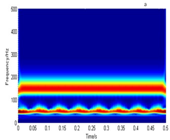
Simulated signal is composed of a sine wave with 150 Hz and a FM modulation component. The modulation frequency is 15 Hz and the fundamental frequency is 50 Hz in the FM signal. Fig. 1(a) shows the time-frequency spectrum of the simulated signal coming from the generalized S transform. From the figure, it can be seen that the energy distribution of signal can be expressed correctly in the S domain time-frequency spectrum. In the frequency band of 150 Hz and 50 Hz, the frequency and amplitude modulation rule of signal is presented very clearly. Fig. 1(b) shows the original simulated signal. Through the inverse S transform, the signal is reconstructed from the time-frequency spectrum shown in Fig. 1(a) according to the Eq. (5)-(7). Fig. 1(c) presents the reconstructed signal. Fig. 1(d) displays the difference between the reconstructed signal and the original signal. From Fig. 1, it can be seen that the reconstructed signal is consistent with the original signal and the error and the original signal differ by 15 orders of magnitude. Error can be ignored, as it is the computational error. There is almost no energy loss between the positive generalized transform to the negative generalized S transforms, which show that the generalized S transform is reversible. The precise time-frequency analysis ability and the reconstruction property of the generalized S transform provide the conditions for its further application in time-frequency domain.
Fig. 1Procession of a frequency modulated and amplitude modulated signal
4. Method to improve resolution
After signal ( sampling points) is applied the generalized S transform, the time-frequency spectrum in every sampling point is obtained as (). The time-frequency spectrum has good ability of time and frequency localization, and the complex problem about time window in Fourier transform is avoided. The energy of signal is redistributed, and energy distribution coefficient can be calculated as following [17-19]:
Among them, is the maximum amplitude of time-frequency spectrum on time series. is a scalar which is used to compromise choosing signal-to-noise ratio (SNR) and resolution. Bigger is , lower is the resolution and higher SNR. On the other hand, smaller value represents higher resolution and lower SNR. Usually, the value of is decided depending on the actual signal noise level. is used to adjust the degree of smooth. For all time point (), the time-frequency spectrum is processed, a new time-frequency spectrum with high resolution can be obtained as:
According to the Eqs. (5)-(7), the signal is reconstructed based on the time-frequency spectrum after energy refactoring, and the signal with high resolution can be obtained. The steps to improve processing can be described as followings.
1) The time-frequency spectrum of vibration signal is obtained based on the generalized S. Then the energy distribution coefficient is calculated and the energy of vibration signal is redistributed according to the Eqs. (9)-(10).
2) The energy distribution coefficient is recalculated. Then by applying inversion S transform according to the Eqs. (5)-(7), the signal with high resolution is reconstructed from the processed time-frequency spectrum.
3) The power spectrum of reconstructed signal is calculated to extract the fault features.
5. Simulation
To prove the validity of the method presented in this paper, the simulated fault signal provided in literature [20] is analyzed as an example:
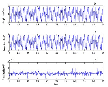
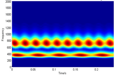
In Eq. (11), 2, 1.0, 0.4, , , , /6, 18, 20. So, the simulated signal is a frequency and amplitude modulation signal. Its main frequency is 360 Hz and 720 Hz. Sampling frequency is 4096 Hz, sampling points are 1000. Fig. 2 shows the time domain waveform of the simulated vibration signal. Fig. 3 displays the time-frequency spectrum in domain and the power spectrum of simulated signal before and after resolution-improvement processing. Fig. 3(a) expresses the time-frequency spectrum in domain before procession. Fig. 3(b) shows the time-frequency spectrum in domain after procession. Fig. 3(c) demonstrates the power spectrum of original signal. Fig. 3(d) displays the power spectrum of the reconstructed signal after resolution-improvement processing. Compared Fig. 3(a) with Fig. 3(b), in the time-frequency spectrum, it can be seen that the time-frequency resolution and the time-frequency concentration of every sampling point is improved significantly after resolution-improvement processing. Also, it can be drawn that the burr in the power spectrum of reconstructed signal is reduced. The amplitude of main frequency component (360 Hz and 720 Hz) is more outstanding and they energy are more concentrated. Obviously, after resolution-improvement processing, the much clearer time-frequency characteristics and power spectrum distribution can be obtained. Resolution improvement procession highlights the main frequency component and improves the resolution of the vibration signal, so as to provide the convenience to improve the accuracy of fault diagnosis.
Fig. 2The time domain waveform of simulated vibration signal
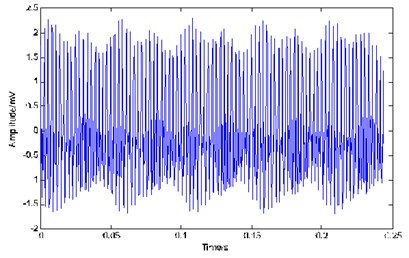
Fig. 3Time-frequency spectrum in S domain and the power spectrum of simulated signal before and after resolution-improvement processing
a)
b)
c)
d)
6. Experiment
The high-resolution time-frequency analysis ability and the reconfigurable feature of the generalized S transform provide the conditions for its further application in time frequency analysis and time-frequency de-noising. Based on the generalized S transform, the time-frequency resolution and time-frequency concentration are obviously improved after resolution-improvement processing. In the power spectrum of reconstructed signal, energy is more concentrated and main frequency component stand out. These features of generalized S transform can be used to analyze the bearing fault signals and improve the accuracy of fault diagnosis.
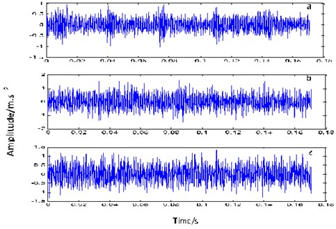
The proposed principles and methods is used to analyze the measured fault signal from the outer ring, inner ring and rolling element of actual bearing. Data comes from the Electrical Engineering Laboratory of Case Western Reserve University. Fig. 4 show the time domain waveform of the measured fault signal. JEM SKF 6205-2RS type bearing is used. Inner diameter of bearing is 25.0012 mm. Outer diameter of bearing is 51.9989 mm. Thickness is 0.5906 mm and the diameter of joint is 39.0398 mm. Rolling body diameter is 15.0012 mm. Damage diameter of outer ring is 0.1778 mm. The number of the rolling element is 9, and the contact angle is 0, the sampling frequency is 12k Hz, the sampling points are 2048.
Fig. 4The time domain waveform of the measured fault signal: a) from inner race, b) from outer race, c) from rolling body
According to the theory, the vibration failure frequency can be calculated by the following equations [21].
Fault frequency on inner race:
Fault frequency on outer race:
Fault frequency on rolling ball:
where, is bearing speed, is ball number, is rolling diameter, is bearing pitch diameter, is rolling contact angle. So, it can be calculated that the inner race fault frequency is 158 Hz, outer race fault frequency is 104 Hz, rolling body fault frequency is 137 Hz.
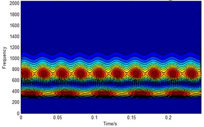
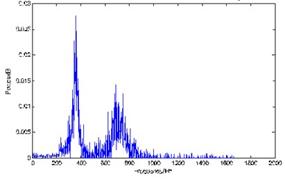
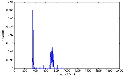
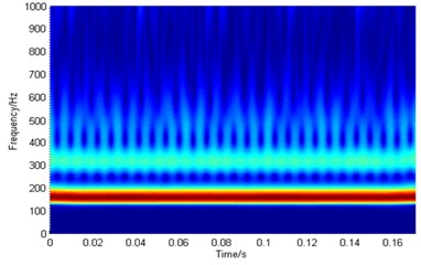
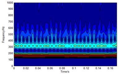
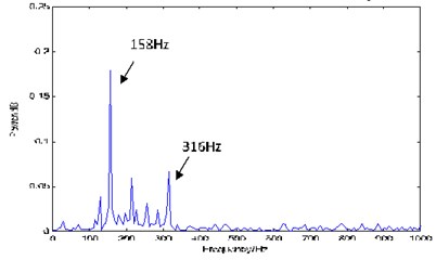
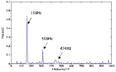
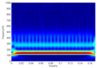
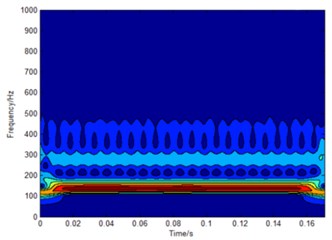
We respectively deal with the fault signal coming from inner race, outer race and rolling body. Analysis results of the inner ring fault signal are revealed firstly. Fig. 5 shows the time-frequency spectrum in domain and the power spectrum of the inner ring fault signal before and after resolution-improvement processing. Fig. 5(a) shows the time-frequency spectrum in domain before processing. Fig. 5(a) displays the time-frequency spectrum in domain after processing. Fig. 5(b) illustrates the time-frequency spectrum in domain after processing. Fig. 5(c) presents the power spectrum of the original inner ring fault signal. Fig. 5(d) demonstrates the power spectrum of the reconstructed signal after resolution-improvement processing. It can be seen from these figures, the time-frequency resolution and the time-frequency concentration of Fig. 5(b) is much higher than that of Fig. 5(a). In Fig. 5(b), the energy distribution region of the signal and its boundary are very clear. Using the time-frequency spectrum shown in Fig. 5(b) to reconstruct inner ring fault signal, the power spectrum of reconstructed signal is presented in Fig. 5(d). There is some obvious peak near 158 Hz, 316 Hz and 374 Hz in Fig. 5(d). 158 Hz is consistent with the fault characteristic frequency of inner ring calculated from theory. 316 Hz and 374 Hz are consistent with its second harmonic and third harmonic respectively. Compared with Fig. 5(c) which shows the power spectrum without resolution-improvement processing, Fig. 5(d) can identify the characteristic frequency of fault signal more effectively.
Fig. 5Time-frequency spectrum in S domain and the power spectrum of the inner ring fault signal before and after resolution-improvement processing
a)
b)
c)
d)
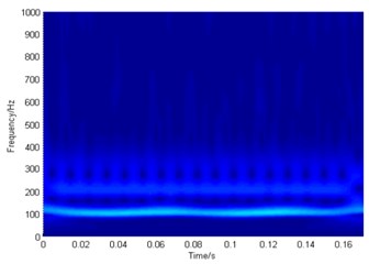
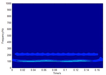
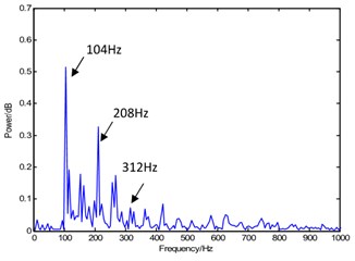
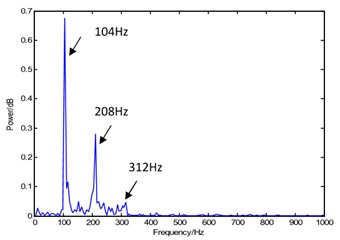
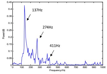
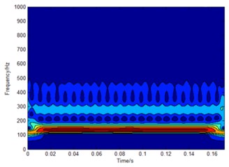
Fig. 6(a), (b), (c) and (d) show the time-frequency spectrum in domain and the power spectrum of outer ring fault signal after resolution-improvement processing. Similar to the analysis of Fig. 5, it can be seen from Fig. 6(d) that there is a significant peak in the vicinity of the frequency 104 Hz which is consistent with the theoretical fault characteristic frequency of the outer ring. There is a fault in the outer ring. The analytical results are consistent with the theoretical results. The second harmonic and the third harmonic are clearer than that in Fig. 6(c). Their side frequency information is more abundant than that in Fig. 6(c). Same conclusion can be obtained from the analysis of Fig. 7(a), (b), (c) and (d), no repeating here.
Obviously, the reconstructed signal after resolution-improvement processing fully utilizes the advantage of the generalized transform. After reallocating the energy of obtained time-frequency spectrum, the reconstructed vibration signal has higher resolution not only in time domain and but also in frequency domain. From the power spectrum of reconstructed signal, bearing condition and fault type can be clearly distinguished and the efficiency of fault diagnosis of bearing is effectively improved.
Fig. 6Time-frequency spectrum in S domain and the power spectrum of the outer ring fault signal before and after resolution-improvement processing
a)
b)
c)
d)
Fig. 7Time-frequency spectrum in S domain and the power spectrum of the rolling body fault signal before and after resolution-improvement processing
a)
b)
c)
d)
7. Conclusions
The domain time-frequency analysis has advantages in the bearing fault diagnosis. The time-frequency spectrum in domain has a strong ability to characterize the dynamically change of energy distribution of bearing fault signal. The nonlinear dynamic characteristics of vibration signal are well portrayed using the S transform. These characteristics suggest that domain time-frequency analysis method has the ability to completely illustrate the local time-frequency characteristics of vibration signal and provide a new way to improve analysis accuracy. The proposed method to redistribute the energy of vibration signal is effective. The energy distribution coefficient is recalculated and the signal with high resolution can be reconstructed from the processed time-frequency spectrum. The processed result of the actual fault signal from the rolling element, inner ring and outer ring affirmatively verify the effectiveness of this method in bearing fault diagnosis. Time-frequency analysis method based on generalized S transformation improves the detection accuracy for bearing fault diagnosis.
References
-
Long J. B., Wang H. B., Li P., Fan H. S. Applications of fractional lower order time-frequency representation to machine bearing fault diagnosis. IEEE/CAA Journal of Automatica Sinica, Vol. 9, Issue 99, 2016, p. 1-17.
-
Ju P. H., Qin S. R., Zhao L. Energy operator demodulating approach based on LMD and its application extracting characteristics of a fault signal. Journal of Mechanical Science and Technology, Vol. 30, Issue 2, 2011, p. 1-4.
-
Kulkarni Sham, Bewoor Anand Vibration based condition assessment of ball bearing with distributed defects. Journal of Measurements in Engineering, Vol. 4, Issue 2, 2016, p. 87-94.
-
Tondon N. A comparison vibration parameters of the condition monitoring of rolling element bearing. Measurement, Vol. 12, 1994, p. 285-289.
-
Utpat Abhay, Ingle R., Nandgaonkar M. Response of various vibration parameters to the condition monitoring of ball bearing used in centrifugal pumps. Noise and Vibration Worldwide, Vol. 42, Issue 6, 2011, p. 34-40.
-
Li H. K., Zhang Z. X., Guo Z. G. Rolling bearing fault diagnosis using Hough transform of time-frequency image. Journal of Vibration, Measurement and Diagnosis, Vol. 30, Issue 6, 2010, p. 634-639.
-
Liu W. Y., Tang B. P., Chen R. X. A fault identification method based on high-order spectral analysis of diagonal slices. Mechanical Science and Technology for Aerospace Engineering, Vol. 29, Issue 3, 2010, p. 281-284.
-
Cai J. H., Hu W. W. Feature extraction of gear fault signal based on Sobel operator and WHT. Shock and Vibration, Vol. 20, 2013, p. 551-559.
-
Chandra N. H., Sekhar A. S. Fault detection in rotor bearing systems using time frequency techniques. Mechanical Systems and Signal Processing, Vol. 72, 2015, p. 105-133.
-
Duan J. S., Xiong X. Y. Research on the application of wavelet transform in weak signal detection. Mechanical Engineering and Automation, Vol. 5, 2007, p. 96-97.
-
Li T. H., Hee-Seok Oh Wavelet spectrum and its characterization property for random process. IEEE Transform Information Theory, Vol. 48, Issue 11, 2002, p. 2922-2937.
-
Stockwcll R. G., Mansinha L. P., Lowc R. Localization of the complex spectrum: the S transform IEEE Transactions on Signal Processing, Vol. 44, Issue 4, 1996, p. 998-1001.
-
Biswal M., Dash P. K. Detection and characterization of multiple power quality disturbances with a fast S-transform and decision tree based classifier. Digital Signal Processing, Vol. 23, Issue 4, 2013, p. 1071-1083.
-
Long J., Wang H., Zha D., Li P., Xie H., Mao L. Applications of fractional lower order S transform time frequency filtering algorithm to machine fault diagnosis. PLoS ONE, Vol. 12, Issue 4, 2017, p. e0175202.
-
Rodríguez A., Aguado J. A., Martín F., López J. J., Muñoz F., Ruiz J. E. Rule-based classification of power quality disturbances using S-transform. Electric Power Systems Research. Vol. 86, 2012, p. 113-121.
-
Raj Kumar, Bhim Singh, Shahani D. T. Recognition of power-quality disturbances using s-transform-based ANN classifier and rule-based decision tree. IEEE Transactions on Industry Applications, Vol. 51, Issue 2, 2015, p. 1249-1258.
-
Zhu D., Gao Q., Sun D., Lu Y., Peng S. A detection method for bearing faults using null space pursuit and S transform. Signal Processing, Vol. 96, Issue 5, 2014, p. 80-89.
-
Simon C., Ventosa S., Schimmel M., et al. The S-transform and its inverses: side effects of discretizing and filtering. IEEE Transaction on Signal Processing, Vol. 55, Issue 10, 2007, p. 4928-4937.
-
Agarwal S., Krishnamoorthy V. ECG signal analysis using wavelet coherence and s-transform for classification of cardiovascular diseases. International Conference on Advances in Computing, Communications and Informatics, Jaipur, India, 2016, p. 1-16.
-
Cai J. H. Fault diagnosis of rolling bearing based on empirical mode decomposition and higher order statistics. Proceedings of IMechE Part C: Journal of Mechanical Engineering Science, Vol. 229, Issue 9, 2015, p. 1630-1638.
-
Yu G., Li C. N., Zhang J. F. A new statistical modeling and detection method for rolling element bearing faults based on alpha-stable distribution. Mechanical Systems and Signal Processing, Vol. 10, Issue 41, 2013, p. 155-175.
Cited by
About this article

The authors wish to acknowledge the assistance and support of all those who contributed to our effort to enhance and develop the described system. The authors express their appreciation for the financial support provided by the National Natural Science Foundation of China (Project No. 41304098) and the Key Research Fund of Hunan Provincial Education Department, PRC (Project No. 16A146). Hunan Provincial Natural Science Foundation of China (Project No. 2017JJ2192, 2017JJ2015).
